EP0376698B1 - Single-use syringe - Google Patents
Single-use syringe Download PDFInfo
- Publication number
- EP0376698B1 EP0376698B1 EP89313615A EP89313615A EP0376698B1 EP 0376698 B1 EP0376698 B1 EP 0376698B1 EP 89313615 A EP89313615 A EP 89313615A EP 89313615 A EP89313615 A EP 89313615A EP 0376698 B1 EP0376698 B1 EP 0376698B1
- Authority
- EP
- European Patent Office
- Prior art keywords
- barrel
- plunger rod
- locking element
- stopper
- body portion
- Prior art date
- Legal status (The legal status is an assumption and is not a legal conclusion. Google has not performed a legal analysis and makes no representation as to the accuracy of the status listed.)
- Expired - Lifetime
Links
Images
Classifications
-
- A—HUMAN NECESSITIES
- A61—MEDICAL OR VETERINARY SCIENCE; HYGIENE
- A61M—DEVICES FOR INTRODUCING MEDIA INTO, OR ONTO, THE BODY; DEVICES FOR TRANSDUCING BODY MEDIA OR FOR TAKING MEDIA FROM THE BODY; DEVICES FOR PRODUCING OR ENDING SLEEP OR STUPOR
- A61M5/00—Devices for bringing media into the body in a subcutaneous, intra-vascular or intramuscular way; Accessories therefor, e.g. filling or cleaning devices, arm-rests
- A61M5/178—Syringes
- A61M5/31—Details
- A61M5/315—Pistons; Piston-rods; Guiding, blocking or restricting the movement of the rod or piston; Appliances on the rod for facilitating dosing ; Dosing mechanisms
-
- A—HUMAN NECESSITIES
- A61—MEDICAL OR VETERINARY SCIENCE; HYGIENE
- A61M—DEVICES FOR INTRODUCING MEDIA INTO, OR ONTO, THE BODY; DEVICES FOR TRANSDUCING BODY MEDIA OR FOR TAKING MEDIA FROM THE BODY; DEVICES FOR PRODUCING OR ENDING SLEEP OR STUPOR
- A61M5/00—Devices for bringing media into the body in a subcutaneous, intra-vascular or intramuscular way; Accessories therefor, e.g. filling or cleaning devices, arm-rests
- A61M5/50—Devices for bringing media into the body in a subcutaneous, intra-vascular or intramuscular way; Accessories therefor, e.g. filling or cleaning devices, arm-rests having means for preventing re-use, or for indicating if defective, used, tampered with or unsterile
- A61M5/5013—Means for blocking the piston or the fluid passageway to prevent illegal refilling of a syringe
-
- A—HUMAN NECESSITIES
- A61—MEDICAL OR VETERINARY SCIENCE; HYGIENE
- A61M—DEVICES FOR INTRODUCING MEDIA INTO, OR ONTO, THE BODY; DEVICES FOR TRANSDUCING BODY MEDIA OR FOR TAKING MEDIA FROM THE BODY; DEVICES FOR PRODUCING OR ENDING SLEEP OR STUPOR
- A61M5/00—Devices for bringing media into the body in a subcutaneous, intra-vascular or intramuscular way; Accessories therefor, e.g. filling or cleaning devices, arm-rests
- A61M5/178—Syringes
-
- A—HUMAN NECESSITIES
- A61—MEDICAL OR VETERINARY SCIENCE; HYGIENE
- A61M—DEVICES FOR INTRODUCING MEDIA INTO, OR ONTO, THE BODY; DEVICES FOR TRANSDUCING BODY MEDIA OR FOR TAKING MEDIA FROM THE BODY; DEVICES FOR PRODUCING OR ENDING SLEEP OR STUPOR
- A61M5/00—Devices for bringing media into the body in a subcutaneous, intra-vascular or intramuscular way; Accessories therefor, e.g. filling or cleaning devices, arm-rests
- A61M5/50—Devices for bringing media into the body in a subcutaneous, intra-vascular or intramuscular way; Accessories therefor, e.g. filling or cleaning devices, arm-rests having means for preventing re-use, or for indicating if defective, used, tampered with or unsterile
- A61M2005/5006—Having means for destroying the syringe barrel, e.g. by cutting or piercing
-
- A—HUMAN NECESSITIES
- A61—MEDICAL OR VETERINARY SCIENCE; HYGIENE
- A61M—DEVICES FOR INTRODUCING MEDIA INTO, OR ONTO, THE BODY; DEVICES FOR TRANSDUCING BODY MEDIA OR FOR TAKING MEDIA FROM THE BODY; DEVICES FOR PRODUCING OR ENDING SLEEP OR STUPOR
- A61M5/00—Devices for bringing media into the body in a subcutaneous, intra-vascular or intramuscular way; Accessories therefor, e.g. filling or cleaning devices, arm-rests
- A61M5/50—Devices for bringing media into the body in a subcutaneous, intra-vascular or intramuscular way; Accessories therefor, e.g. filling or cleaning devices, arm-rests having means for preventing re-use, or for indicating if defective, used, tampered with or unsterile
- A61M5/5013—Means for blocking the piston or the fluid passageway to prevent illegal refilling of a syringe
- A61M5/502—Means for blocking the piston or the fluid passageway to prevent illegal refilling of a syringe for blocking the piston
- A61M2005/5033—Means for blocking the piston or the fluid passageway to prevent illegal refilling of a syringe for blocking the piston by use of an intermediate blocking member positioned between the syringe barrel and the piston rod to prevent retraction of the latter, e.g. toothed clip placed on the piston rod
Definitions
- the present invention relates to syringes and more particularly concerns disposable syringes having single-use features as specified in the preamble of Claim 1.
- a syringe is known from US-A-4731068.
- hypodermic syringe products which are intended for single use only is instrumental in drug abuse and more particularly in the transfer of contagious diseases.
- Intravenous drug users who routinely share and reuse syringes are a high risk group with respect to the AIDS virus.
- the effects of multiple use are a major concern in third world countries where repeated use of syringe products may be responsible for the spread of many diseases.
- Reuse of single-use hypodermic syringe assemblies is also instrumental in the spread of drug abuse even in the absence of infection or disease.
- U.S. Patent No. 4,367,738 to Legendre et al. teaches a syringe having a barrel with a restricted open end which interacts with a plunger rod having a plurality of short flexible spikes attached at an oblique angle away from the piston.
- the oblique spikes will pass through the restricted opening in the barrel but the plunger rod motion in a reverse direction will be prevented by the oblique spikes.
- the syringe of Legendre et al. is suitable only for prefilled use because the plunger rod can not be fully withdrawn.
- the plunger rod of this syringe may be moved back and forth, as to reuse, for the distance between tips on the spike.
- U.S. Patent No. 4,781,683 to Wozniak et al. teaches a single-use syringe that is rendered inoperative without requiring any deliberate action on the part of the user.
- Wozniak et al. accomplished this result by providing a hydrophilic expansion plug which is positioned in the outlet channel of the syringe which expands a short time after being exposed to a drug containing water to render the syringe inoperative.
- the syringe of Wozniak et al. may not function in a prefilled mode wherein the syringe is filled through the hypodermic needle because the syringe would probably be rendered inoperative before the time of use.
- syringes are prefilled through the delivery tip in the hospital pharmacy and sent to the nursing stations for use immediately or during the next several hours or days. It would appear that the syringe of Wozniak et al. would not be applicable to this use because it would be rendered inoperative before time of use unless the hydrophilic expansion plug required an extended amount of time to reacts, and in this latter case it would not be a single-use syringe.
- Trenner Another single-use hypodermic syringe is taught by Trenner in U.S. Patent No. 4,781,684.
- Trenner appears to have overcome many of the shortcomings of the prior art with respect to the most common application of hypodermic syringes which is syringes being filled through the needle tip at the time of use or within a short period of time before use.
- the syringe of Trenner appears to allow for the easy filling and substantially unrestricted use.
- Trenner provides an annular groove near the distal end of the syringe barrel having a diameter which is greater than the diameter of the cylindrical inner surface of the barrel.
- a locking element positioned between the stopper and the plunger rod, has an outside diameter which is larger than the diameter of the barrel so that when the syringe stopper is moved to its furthest-most position inside the barrel, expelling medicament from the syringe, the locking element engages the annular groove and prevents withdrawal of the stopper.
- the design appears to allow the forced disconnection of the plunger rod from the stopper while still retaining the stopper in the barrel. While the approach of Trenner overcomes many of the shortcomings of the prior art the Trenner syringe can be recycled many times so long as the user is careful not to move the stopper all the way to the distal end so as to engage the locking element with the annular groove.
- US Patent 4731068 to Hesse describes a non-reloadable syringe wherein the plunger unit is permitted to be withdrawn for loading of the syringe and to be urged forward to discharge the contents of the syringe. Means are provided whereby subsequent retraction of the plunger assembly is inhibited to prevent further loading and use of the syringe.
- Hesse employs a spider element with prongs which can be brought into use to prevent proximal motion of the plunger rod, and a separate sleeve element to keep the prongs from prematurely engaging the syringe barrel. This sleeve element also serves to limit the delivery volume of the syringe assembly by establishing the maximal proximal position of the spider element with respect to the syringe barrel
- An operable single-use syringe assembly of the present invention includes a barrel having an inside surface describing a chamber for retaining fluid, an open barrel end, and a distal barrel end having a passageway therethrough in fluid communication with the chamber.
- a plunger rod having an elongate body portion, a proximal end and a distal end is provided.
- a stopper at the distal end of the plunger rod is slidably positioned in fluid-tight engagement inside the barrel.
- a locking element is positioned in the barrel between the elongate body portion of the plunger rod and the inside surface of the barrel.
- the locking element includes a proximally and outwardly facing locking barb, a distally and inwardly facing resisting edge and an inwardly facing driving edge.
- the driving edge of the locking element is adapted to interact with the elongate body portion of the plunger rod to move the locking element along the barrel as the stopper is advanced along the barrel.
- the resisting edge and the barb are adapted to prevent proximal motion of the plunger rod with respect to the barrel after the initial distal motion of the stopper to expel fluid through said passageway wherein proximal motion of the plunger rod with respect to the barrel causes the resisting edge to engage the plunger rod causing the locking element to move in a proximal direction wherein the locking barb engages the inside surface of the barrel to prevent further proximal movement and allowing only distal movement of the plunger rod with respect to the barrel.
- Barrier means is provided on the elongate body portion of the plunger rod for limiting the delivery volume of the syringe assembly by establishing the maximum proximal position of the locking element with respect to the elongate body portion.
- the elongate body portion of the plunger body can include a longitudinal recess acting as a pathway for the longitudinal motion of the locking element relative to the elongate body portion between said stopper and said barrier means.
- the longitudinal recess is v-shaped when viewed along the longitudinal axis of the body portion with the narrowest portion of the recess being closest to the center of the body portion.
- a delivery ledge can be formed in the recess for engaging the driving edge when the locking element is in about its furthest most distal position with respect to the recess for assuring distal motion of the locking element as the plunger moves distally along the barrel to expel fluid from the chamber.
- Suitable forms for the ledge include a raised rib, or a recessed groove in the recess.
- the locking element of the syringe assembly can include a second proximally and outwardly facing locking barb and and a second inwardly facing driving edge at said proximal portion of said element.
- the driving edges of such a locking element having a second driving edge can be separated by a longitudinal gap in the element so that the driving edges extend proximally in cantilever spring-like fashion from the distal portion of the element forcing the locking barb and the second locking barb against the inside surface of the barrel.
- the syringe assembly can have stopper support means on the shaft portion adjacent to the stopper for supporting the stopper during distal motion of the stopper with respect to the barrel.
- the support means then establishes the maximal distal position of the locking element with respect to the elongate body portion.
- Tamper resisting barrier means can be provided on the body portion located proximally of the intended path of the locking element along the body portion.
- the body portion of the plunger rod can include weakening means located proximally of the barrier means for allowing twisting failure of the plunger rod upon application of excessive torsional force to the proximal end of said body portion, the weakening means including an area of reduced transverse cross-sectional thickness.
- a syringe assembly 20 having single-use features, includes a barrel 21 having an inside surface 22 describing a chamber 23 for retaining fluid.
- Barrel 21 includes an open end 25 and a distal barrel end 27 having a passageway 28 therethrough in fluid communication with chamber 23.
- a needle cannula 29 having a sharpened distal tip 31 and a lumen therethrough in fluid communication with passageway 28 projects outwardly from distal barrel end 27.
- the syringe of the instant invention is preferably used with a cannula which is attached to the distal end of the syringe using adhesives or other suitable means.
- the instant syringe may be used in applications not requiring a needle attached directly to the syringe such as with a removable needle and hub assembly or in other applications not requiring a needle where its single use features are desired, and that the attached canpula of the preferred embodiment is only one of these many possibilities.
- distal end is meant to refer to the end furthest from the person holding the syringe
- proximal end is meant to refer to the end closest to the holder of the syringe
- a plunger assembly 32 includes a stopper 39 and a plunger rod 33 having an elongate body portion 34.
- the elongate body portion includes a longitudinal recess 35, a proximal end 37, and a distal end 38.
- the longitudinal recess is v-shaped when viewed along the longitudinal axis of elongate body portion 34 with the narrowest portion of the recess being closes to the center of the elongate body portion.
- stopper 39 is positioned at distal end 38 of the plunger rod. The stopper is slidably positioned in fluid-tight engagement in the barrel while a portion of body portion 34 of the plunger rod extends outwardly from open end 25 of the barrel.
- the plunger rod is accessible outside of open end 25 of the barrel and is provided to move the stopper along the barrel to force fluid into and out of the chamber 23 through passageway 28.
- Disc-shaped plunger rod flange 40 is provided as a convenient structure for applying forces to move the plunger rod with respect to barrel 21.
- a flange 41 is also provided at the proximal end of the barrel to facilitate handling and positioning the syringe and for maintaining the relative position of the barrel with respect to the plunger rod during filling and medication administration.
- plunger rods and stoppers which are integrally formed of the same material or different materials, such as in two-color molding, or separately formed of the same or different materials and joined together by mechanical means, adhesive, ultraonsonic welding, heat sealing or other suitable means. It is understood that the plunger rod assembly of this preferred embodiment is merely illustrative of these many possibilities.
- a locking element 42 is positioned in the barrel and partially within longitudinal recess 35 between the plunger rod and the inside surface 22 of the barrel. Longitudinal recess 35 of the plunger rod acts as a pathway for longitudinal motion of the locking element relative to the elongate body portion of the plunger rod.
- Element 42 includes a proximal portion 44.
- Proximal portion 44 includes a proximally and outwardly facing locking barb 46.
- proximal portion 44 also includes two additional anti-twist locking barbs 47 and 49 which are preferably not facing in the same direction as locking barb 46. Locking barbs 47 and 49 are optional but important in helping prevent misuse of the instant syringe to overcome the single-use function by twisting the plunger rod as will be explained in more detail hereinafter.
- Locking element 42 is preferably formed of planar sheet material 43 which is preferably harder than the material of the barrel and the plunger rod such as metal.
- locking barb 46 remain in the plane of sheet metal 43 while anti-twist locking barbs 47 and 49 are positioned at angles with respect to the locking barb preferably with each anti-twist locking barb being angled away from the locking barb 46 on different sides of the locking barb as best illustrated in Fig. 10.
- at least two proximally and outwardly facing locking barbs are provided. If two barbs are used it is preferable that these barbs are included with respect to each other at an angle within the range of about five (5) degrees to ninety (90) degrees.
- the second locking barb or first anti-twist locking barb is preferably located in a plane positioned at an angle of between about five (5) degrees to ninety (90) degrees with respect to the plane of locking barb and the third locking barb or second anti-twist locking barb is located in a plane positioned at an angle of between about five (5) degrees and ninety (90) degrees with respect to the plane of the locking barb and preferably oriented toward the opposite side of the plane of the locking barb as the first anti-twist locking barb.
- the relationship of the barbs, when the locking element is made of sheet metal is established by bending one or more of the barbs so that the barbs point in different directions as a result of the barb or barbs being bent.
- Locking element 42 also includes a distally and inwardly facing resisting edge 50 and an inwardly facing driving edge 52 at proximal portion 44 of the locking element.
- the term “inwardly” shall mean toward a surface on the plunger rod body portion such as a surface along longitudinal groove 35, and the term “outwardly” shall mean facing generally toward inside surface 22 of barrel 21.
- Driving edge 52 is adapted to interact with longitudinal recess of the plunger rod to move the locking element along the barrel as the stopper is advanced along the barrel by force applied to the plunger rod.
- driving edge 52 also, because of its orientation, allows proximal motion of the plunger rod with respect to the barrel during filling while helping to keep the locking element in a fixed position with respect to said barrel.
- Resisting edge 50 and the locking barbs are adapted to prevent proximal motion of plunger rod 33 with respect to barrel 21 after initial distal motion of the stopper on the plunger rod to expel fluid through passageway 28.
- locking element 42 further includes a second inwardly facing driving edge 53 at proximal portion 44 and a second proximally and outwardly facing locking barb 56 adjacent to additional anti-twist locking barbs 57 and 59 which are angularly oriented away from second locking barb 56 and preferably at different angles with respect to each other.
- Locking barbs 46, 47 and 49 and driving edge 52 are separated from second locking barbs 56, 57 and 59 and second driving edge 53 by longitudinal gap 61 so that driving edge 52 and second driving edge 53 extend proximally in cantilever spring-like fashion from distal portion 45 acting to force locking barb 46 and second locking barb 56 against the inside surface of the barrel.
- a locking element with spring-like qualities such as a locking element formed of metal such as berelium copper or stainless steel with stainless steel sheet metal being preferred for medical applications.
- the stainless steel sheet metal have a thickness of between about 0.003 inch (0.076 mm) to 0.20 inch (0.508 mm) when used in a syringe barrel having an inside diameter of about 0.333 inch (8.5 mm).
- Longitudinal gaps 61 divides proximal portion 44 into two cantilever spring arms 62 and 63 which are preferably bent along preferably variable radius R so that the distance across the locking element at the locking barbs is larger than the space available between the plunger rod and the inside surface of the syringe barrel. This configuration requires compression of the spring arms upon assembly and, as will be explained in more detail hereinafter, provides a slight pressure of the locking barbs against the inside surface of the barrel.
- the syringe of the present invention may be used with a plurality of locking elements, for example, the preferred embodiment will accept up to four separate locking elements to provide additional mechanical resistance to multiple use.
- a locking element and/or plunger rod may be shaped so that a single larger locking element engages areas further apart on the inside surface of the syringe barrel such as along 90 degrees to 360 degrees of the inside diameter of a circularly shaped syringe barrel.
- An important feature of the instant invention is its ability to provide a syringe assembly having structure for limiting the volume of fluid with which can be taken into the chamber through passageway 28 and subsequently delivered. This feature assists in achieving substantially consistent delivery volumes from syringe to syringe and is useful in programs involving large numbers of subjects being injected with medication at the same time such as immunization programs. This feature also prevents misuse by limiting the volume the syringe assembly is capable of delivering. To limit delivery volume a barrier means such as delivery limiting barrier 65 is provided. Delivery limiting barrier 65 establishes the maximum proximal position of locking element 42 with respect to the elongate body portion of the plunger rod.
- the barrier function can be accomplished by various structures such as a raised rib positioned transversely along the surface of the plunger rod in the area of the longitudinal recess as will be described hereinafter.
- the delivery limiting barrier provides an obstacle in longitudinal recess 35 over which locking element 42 cannot pass. Accordingly, when the locking element contacts delivery limiting barrier 65 it is forced along the barrel with the plunger rod.
- the delivery limiting barrier in this embodiment is a circular flange. It is within the purview of the instant invention to include barrier means which is fixed to the plunger rod such as delivery limiting barrier 65 or movable thereon to adjust the volume of the syringe.
- a ledge such as delivery ledge 67 running transversely across longitudinal recess 35.
- Delivery ledge 67 includes inclined surface 68 and vertical edge wall 69.
- Delivery ledge 67 is positioned at a distance which is approximately the overall length of the locking element from the proximal side of the stopper or any structure in the longitudinal recess defining the proximal-most limit of the recess, such as support wall 30.
- Delivery ledge 67 in the preferred embodiment is positioned at a distance of approximately the length of the locking element proximally from support wall 30 so that edge wall 69 is positioned at a distance slightly longer than the length of the locking element from support wall 30.
- Delivery ledge 67 is lower and less pronounced than the delivery limiting barrier because it is configured to allow the locking element to pass thereover when the locking element moves distally with respect to the plunger rod but to positively engage driving edges 52 and 53 with vertical edge wall 69 when the element moves proximally with respect to the plunger rod.
- the delivery ledge is formed by a recessed-groove in recess 35, however, it is also within the purview of the instant invention to include a delivery ledge formed of a raised projection such as a raised rib.
- the locking element will slide along the longitudinal recess of the plunger rod while air is being forced from the chamber through the passageway in the needle cannula until the locking element abuts against delivery limiting barrier 65. Then the locking element will move with the plunger rod toward the distal end of the syringe barrel.
- the plunger rod In use, when drawing medication into the chamber through the needle cannula, the plunger rod will move in a proximal direction while the locking element will tend to remain stationary with respect to the barrel until it abuts against support wall 30. This position, as will be explained in more detail hereinafter, defines the maximum volume of the syringe.
- medication may be delivered from the syringe by moving the plunger rod in a distal direction with respect to the barrel such as by applying force to disc-shaped plunger rod flange 40.
- driving edges 52 and 53 tend to engage the plunger rod surface in the longitudinal recess and travel with the plunger rod. In almost all cases this phenomenon will occur readily because of the higher hardness of the locking element which is forced by its spring action against the plunger rod longitudinal recess.
- delivery ledge 67 through its vertical ledge 69 further facilitates the engagement of driving edges 52 and 53 and the plunger rod longitudinal recess 35.
- delivery ledge 67 is shaped to have inclined surface 68 at its distal side and vertical edge wall 69 at its proximal side. It is also within the purview of this invention to include a delivery ledge which is raised from the surface of the plunger rod longitudinal recess 35 to accomplish the same result.
- a tamper resistant barrier 71 is positioned transversely with respect to the plunger rod wall to block access to the locking element through open end 25 of the barrel in order to prevent unwanted tampering with the locking element to defeat the single-use function of the instant invention. It may be possible to use a long instrument such as forceps to reach in and disengage the locking element or to forceably remove it. Tamper resistant barrier 71 acts to prevent this access. In the preferred embodiment, although it is not necessary, the tamper resistant barrier 71 and delivery limiting barrier 65 occupy the same position along the axial length of the plunger rod. A different embodiment of the plunger rod wherein the delivery limiting barrier and the tamper resistant barrier are at separate positions along the plunger rod will be described hereinafter.
- the weakening means includes an area of reduced transverse cross-sectional thickness 73, as best illustrated in Fig. 7, which helps to allow the plunger rod to break if excessive an unnecessary amounts of force are applied at the proximal end.
- a person attempting to defeat the single-use function of the instant invention may attempt to do so by twisting or bending the plunger rod in order to distort or defeat the locking element.
- the area of reduced transverse cross-sectional thickness in the plunger rod will greatly reduce the resistance of the plunger rod to bending or torsional forces causing it to fail.
- thickness anti-twist locking barbs 47 and 49 and additional anti-twist locking barbs 57 and 59 which are angled out of the plane of locking barbs 46 and 56 respectively are oriented to dig into the syringe barrel wall upon the application of torsional force.
- anti-twist locking barbs 47 and 57 would tend to resist torsional rotation in one direction while anti-twist locking barbs 49 and 59 would tend to resist torsional rotation of the plunger rod with respect to the barrel in the opposite direction.
- the syringe assembly of the instant invention may be assembled by placing the stopper in the barrel with the plunger rod projecting outwardly from open end 25 of the barrel and then placing locking element 42 in the longitudinal recess in a position which is distal to delivery limiting barrier 65 and then forcing the stopper and plunger rod along the barrel until the stopper is in about its distal-most position, as illustrated in Fig. 12.
- locking element 42 will, because of its spring action and locking barbs, remain substantially in one position with respect to the barrel until driving edges 52 and 53 contact delivery limiting barrier 65 and causes the locking element to move with the plunger rod to the position illustrated in Fig. 12.
- the syringe needle if it is not already in fluid communication with a source of medication, may be placed in a stoppered vial containing medication to be injected (not shown) and the plunger rod withdrawn so that medication 74 is drawn into the chamber as best illustrated in Fig. 13.
- the locking element 42 remains in a fixed position with respect to the barrel. This position of the locking element relative to the barrel defines the maximum volume which the syringe assembly will deliver and is established when support wall 30 of the plunger rod contacts resisting edge 50 of the locking element. Further proximal motion of the plunger rod will not occur because the locking element barbs will engage barrel inside surface 22 to resist this motion.
- the syringe is now ready for administering medication to a patient using known safe procedures.
- the syringe assembly of the instant invention will be in the position illustrated in Fig. 14.
- the locking element While medication is being delivered the locking element will move with the plunger rod along the barrel in a proximal direction because driving edges 52 and 53 are engaging the plunger rod with enough force to prevent any slipping.
- To facilitate the motion of locking element 42 toward the distal end of the barrel delivery ledge 67 is provided on the preferred embodiment to help improve the engagement between driving edges 52 and 53 and the plunger rod.
- any attempt to dislodge the locking element by applying torsional force to the plunger rod will be resisted by the locking element and cause the plunger rod to fracture or break at the area of reduced transverse cross-sectional thickness 73. Also, an attempt to subsequently remove or disarm the locking element will be resisted by tamper resistant barrier 71.
- the locking element may be placed in the syringe, as illustrated in Fig. 11, during manufacturing and packaged and sterilized while it is in the position illustrated in Fig. 12.
- the syringe may be packaged and sterilized in a position when the stopper is positioned a distance from the distal end of the barrel so that the syringe contains sterile air which may be used to pressurize the stoppered vial containing medication before drawing medication into the chamber, using known safe procedures.
- an alternative embodiment of the plunger rod and stopper of the instant invention is illustrated.
- the structure of the plunger rod and stopper is substantially similar to the plunger rod and stopper of the embodiment of Figs. 1-10. Accordingly, substantially similar components that perform substantially similar functions will be numbered identically to those components of the embodiment of Figs. 1-10 except a suffix "a" will be used to identify these components in Figs. 15 and 16.
- the barrel and locking element although not shown are identical to the embodiment of Figs. 1-10.
- an alternative plunger rod and stopper assembly 80 includes a plunger rod 81 having a proximal end 83 and a distal end 85.
- a stopper 39a at distal end 85 is slidably positioned in fluid-tight engagement in the barrel (not shown).
- Plunger rod 81 includes barrier means on the body portion for limiting the delivery volume of the syringe assembly by establishing the maximum proximal position of the locking element (not shown) with respect to elongate body portion 82 of the plunger rod.
- barrier means includes raised rib 86 running transversely across longitudinal recess 35a of elongate body portion 82.
- the plunger rod also includes stopper support means including support wall 30a adjacent to stopper 39a for supporting the stopper during distal motion of the stopper with respect to the barrel.
- Support wall 30a in this embodiment, is a support flange positioned transversely with respect to longitudinal axis 87 of elongate body portion 82.
- the plunger rod also includes tamper-resistant barrier 88 in the shape of a barrier flange positioned transversely with respect to longitudinal axis 87.
- An area of reduced transverse cross-sectional thickness 73a is also provided in a position which is proximal to tamper-resistant barrier 88 for allowing twisting failure of the plunger rod on application of excessive force to proximal end 83 of the plunger rod.
- Plunger rod 81 also includes delivery ledge 91 in the form of a raised projection running transversely along longitudinal recess 35a.
- Delivery ledge 91 includes inclined surface 92 and vertical edge wall 93. Delivery ledge 91 in this embodiment is positioned so that the distance between support wall 30a and vertical edge wall 93 is slightly larger than the length of the locking element (not shown). As with the embodiment of Figs. 1-10, the positioning of the delivery ledge is determined by the distance between the support wall and the vertical edge wall.
- the syringe barrel of the present invention may be constructed of a wide variety of rigid materials with thermoplastic materials such as polypropylene and polyethylene being preferred. Similarly thermoplastic materials such as polypropylene, polyethylene and polystyrene are preferred for the plunger rod. A wide variety of materials such as natural rubber, synthetic rubber and thermoplastic elastomers are suitable for the stopper. The choice of stopper material will depend on compatability with the medication being used. In the preferred embodiment of this invention the stopper, made of medical grade rubber, includes a partially hollow interior with an undercut ledge which is snap-fit over a complementary structure on the plunger rod to secure the stopper to the plunger rod. A stopper and plunger rod may also be integrally formed of the same material or of different materials.
- the locking element being fabricated from a material which is harder than the barrel and plunger rod material so that the locking barbs and resisting edge and driving edge may effectively engage these components.
- Resilient spring-like properties are also desirable along with low cost dimensionally consistent fabrication.
- sheet metal is the preferred material for the locking element with stainless steel being preferred for medical applications.
- the locking element of the preferred embodiment is fabricated from a single sheet, it is within the purview of the instant invention to include locking elements made of other forms of material such as wire and locking elements containing multiple parts and apparatus such as hinges and springs to achieve the function of the preferred locking element.
- the present invention provides a simple, straight-forward, reliable, easily fabricated, single-use syringe having features such as: barrier means for establishing syringe delivery volume; a delivery ledge for more precise interaction of the single-use syringe assembly elements; and various features such as non-parallel locking barbs, tamper-resistant barrier means on the plunger rod, and an area of reduced transverse cross-sectional thickness on the plunger rod to help prevent misuse.
- the present invention provides a single-use syringe which becomes inoperable or incapable of further use without any additional act on the part of the user.
Abstract
Description
- The present invention relates to syringes and more particularly concerns disposable syringes having single-use features as specified in the preamble of Claim 1. Such a syringe is known from US-A-4731068.
- In the United States and throughout the world the multiple use of hypodermic syringe products which are intended for single use only is instrumental in drug abuse and more particularly in the transfer of contagious diseases. Intravenous drug users who routinely share and reuse syringes are a high risk group with respect to the AIDS virus. Also, the effects of multiple use are a major concern in third world countries where repeated use of syringe products may be responsible for the spread of many diseases. Reuse of single-use hypodermic syringe assemblies is also instrumental in the spread of drug abuse even in the absence of infection or disease.
- Many attempts have been made to remedy this problem. Most notable are early contributions which relied on a specific act to destroy the syringe after use either by using a destructive device or providing a syringe assembly with frangible zones so that the syringe could be rendered inoperable by the application of force. Other attempts involve the inclusion of structure which would allow the destruction or defeating of the syringe function through a conscious act by the syringe user. Although many of these devices work quite well they do require the specific intent of the user followed by the actual act to destroy or render the syringe inoperable. None of these devices is effective with a user having the specific intent to reuse the hypodermic syringe. Accordingly, there is a need for a single-use hypodermic syringe which becomes inoperative or incapable of further use automatically without any additional act on the part of the user. This automatic function is much harder to provide because the means for rendering the syringe inoperable must not prevent its filling or use under normal conditions.
- Along these lines, U.S. Patent No. 4,367,738 to Legendre et al. teaches a syringe having a barrel with a restricted open end which interacts with a plunger rod having a plurality of short flexible spikes attached at an oblique angle away from the piston. During injection, the oblique spikes will pass through the restricted opening in the barrel but the plunger rod motion in a reverse direction will be prevented by the oblique spikes. The syringe of Legendre et al. is suitable only for prefilled use because the plunger rod can not be fully withdrawn. The plunger rod of this syringe may be moved back and forth, as to reuse, for the distance between tips on the spike. For example, if the tips on adjacent spikes are one centimeter apart, when measured along the axis of the plunger rod the piston would appear to be cyclable back and forth for a distance slightly less than one centimeter. This syringe of Legendre et al. must have many spikes along the axis of the plunger rod to be rendered unreusable as a practical matter. A solution to the problem of multiple use which only addresses prefilled syringes is limited in nature because millions of injections each year are performed with vaccines that must be used a short time after being placed into injectable form by mixing with water.
- U.S. Patent No. 4,781,683 to Wozniak et al. teaches a single-use syringe that is rendered inoperative without requiring any deliberate action on the part of the user. Wozniak et al. accomplished this result by providing a hydrophilic expansion plug which is positioned in the outlet channel of the syringe which expands a short time after being exposed to a drug containing water to render the syringe inoperative. The syringe of Wozniak et al. may not function in a prefilled mode wherein the syringe is filled through the hypodermic needle because the syringe would probably be rendered inoperative before the time of use. Also, in many hospital applications, syringes are prefilled through the delivery tip in the hospital pharmacy and sent to the nursing stations for use immediately or during the next several hours or days. It would appear that the syringe of Wozniak et al. would not be applicable to this use because it would be rendered inoperative before time of use unless the hydrophilic expansion plug required an extended amount of time to reacts, and in this latter case it would not be a single-use syringe.
- Another single-use hypodermic syringe is taught by Trenner in U.S. Patent No. 4,781,684. Trenner appears to have overcome many of the shortcomings of the prior art with respect to the most common application of hypodermic syringes which is syringes being filled through the needle tip at the time of use or within a short period of time before use. The syringe of Trenner appears to allow for the easy filling and substantially unrestricted use. Trenner provides an annular groove near the distal end of the syringe barrel having a diameter which is greater than the diameter of the cylindrical inner surface of the barrel. A locking element, positioned between the stopper and the plunger rod, has an outside diameter which is larger than the diameter of the barrel so that when the syringe stopper is moved to its furthest-most position inside the barrel, expelling medicament from the syringe, the locking element engages the annular groove and prevents withdrawal of the stopper. The design appears to allow the forced disconnection of the plunger rod from the stopper while still retaining the stopper in the barrel. While the approach of Trenner overcomes many of the shortcomings of the prior art the Trenner syringe can be recycled many times so long as the user is careful not to move the stopper all the way to the distal end so as to engage the locking element with the annular groove.
- US Patent 4731068 to Hesse describes a non-reloadable syringe wherein the plunger unit is permitted to be withdrawn for loading of the syringe and to be urged forward to discharge the contents of the syringe. Means are provided whereby subsequent retraction of the plunger assembly is inhibited to prevent further loading and use of the syringe. Hesse employs a spider element with prongs which can be brought into use to prevent proximal motion of the plunger rod, and a separate sleeve element to keep the prongs from prematurely engaging the syringe barrel. This sleeve element also serves to limit the delivery volume of the syringe assembly by establishing the maximal proximal position of the spider element with respect to the syringe barrel
- An operable single-use syringe assembly of the present invention includes a barrel having an inside surface describing a chamber for retaining fluid, an open barrel end, and a distal barrel end having a passageway therethrough in fluid communication with the chamber. A plunger rod having an elongate body portion, a proximal end and a distal end is provided. A stopper at the distal end of the plunger rod is slidably positioned in fluid-tight engagement inside the barrel. A locking element is positioned in the barrel between the elongate body portion of the plunger rod and the inside surface of the barrel. The locking element includes a proximally and outwardly facing locking barb, a distally and inwardly facing resisting edge and an inwardly facing driving edge. The driving edge of the locking element is adapted to interact with the elongate body portion of the plunger rod to move the locking element along the barrel as the stopper is advanced along the barrel. The resisting edge and the barb are adapted to prevent proximal motion of the plunger rod with respect to the barrel after the initial distal motion of the stopper to expel fluid through said passageway wherein proximal motion of the plunger rod with respect to the barrel causes the resisting edge to engage the plunger rod causing the locking element to move in a proximal direction wherein the locking barb engages the inside surface of the barrel to prevent further proximal movement and allowing only distal movement of the plunger rod with respect to the barrel. Barrier means is provided on the elongate body portion of the plunger rod for limiting the delivery volume of the syringe assembly by establishing the maximum proximal position of the locking element with respect to the elongate body portion.
- The elongate body portion of the plunger body can include a longitudinal recess acting as a pathway for the longitudinal motion of the locking element relative to the elongate body portion between said stopper and said barrier means. Suitably the longitudinal recess is v-shaped when viewed along the longitudinal axis of the body portion with the narrowest portion of the recess being closest to the center of the body portion.
- In the syringe assembly, a delivery ledge can be formed in the recess for engaging the driving edge when the locking element is in about its furthest most distal position with respect to the recess for assuring distal motion of the locking element as the plunger moves distally along the barrel to expel fluid from the chamber. Suitable forms for the ledge include a raised rib, or a recessed groove in the recess.
- The locking element of the syringe assembly can include a second proximally and outwardly facing locking barb and and a second inwardly facing driving edge at said proximal portion of said element. The driving edges of such a locking element having a second driving edge can be separated by a longitudinal gap in the element so that the driving edges extend proximally in cantilever spring-like fashion from the distal portion of the element forcing the locking barb and the second locking barb against the inside surface of the barrel.
- The syringe assembly can have stopper support means on the shaft portion adjacent to the stopper for supporting the stopper during distal motion of the stopper with respect to the barrel. The support means then establishes the maximal distal position of the locking element with respect to the elongate body portion.
- Tamper resisting barrier means can be provided on the body portion located proximally of the intended path of the locking element along the body portion.
- The body portion of the plunger rod can include weakening means located proximally of the barrier means for allowing twisting failure of the plunger rod upon application of excessive torsional force to the proximal end of said body portion, the weakening means including an area of reduced transverse cross-sectional thickness.
-
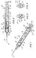
- Fig. 1 is a perspective view of the single-use syringe assembly of the present invention;
- Fig. 2 is a side elevation view of the single-use syringe assembly of Fig. 1;
- Fig. 3 is a side elevation view of the distal end of the single-use syringe assembly of Fig. 2;
- Fig. 4 is a side elevation view of the proximal end of the single-use syringe assembly of Fig. 2;
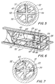
- Fig. 5 is an enlarged cross-sectional view of the single-use syringe of Fig. 2 taken along line 5-5;
- Fig. 6 is an enlarged partial cross-sectional perspective view of the portion of the syringe assembly of Fig. 1 containing the locking element;
- Fig. 7 is an enlarged cross-sectional view of the single-use syringe assembly of Fig. 2 taken along line 7-7.
- Fig. 8 is an enlarged top plan view of the locking element blank illustrating details of the locking element before forming;
- Fig. 9 is a side elevation view of the locking element of the instant invention before assembly into the single-use syringe assembly of the instant invention;
- Fig. 10 is a side elevation view of the end of the locking element of Fig. 9;
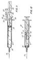
- Figs. 11-14 illustrate the single-use syringe assembly of the present invention in use;
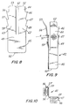
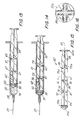
- Fig. 15 is a side elevation view of an alternative plunger rod assembly for use in the instant invention; and
- Fig. 16 is a cross-sectional view of the plunger rod assembly of Fig. 15 taken along lines 16-16.
- While this invention is satisfied by embodiments in many different forms, there is shown in the drawings and will herein be described in detail preferred embodiments of the invention with the understanding that the present disclosure is to be considered as exemplary of the principles of the invention and is not intended to limit the invention to the embodiments illustrated.
- Adverting to Figs. 1 through 10, a
syringe assembly 20, having single-use features, includes abarrel 21 having aninside surface 22 describing achamber 23 for retaining fluid.Barrel 21 includes anopen end 25 and a distal barrel end 27 having apassageway 28 therethrough in fluid communication withchamber 23. Aneedle cannula 29 having a sharpeneddistal tip 31 and a lumen therethrough in fluid communication withpassageway 28 projects outwardly fromdistal barrel end 27. The syringe of the instant invention is preferably used with a cannula which is attached to the distal end of the syringe using adhesives or other suitable means. It will be apparent to one skilled in the art that the instant syringe may be used in applications not requiring a needle attached directly to the syringe such as with a removable needle and hub assembly or in other applications not requiring a needle where its single use features are desired, and that the attached canpula of the preferred embodiment is only one of these many possibilities. - For the purposes of the description of the present invention, the term "distal end" is meant to refer to the end furthest from the person holding the syringe, whereas the term "proximal end" is meant to refer to the end closest to the holder of the syringe.
- A
plunger assembly 32 includes astopper 39 and aplunger rod 33 having anelongate body portion 34. The elongate body portion includes alongitudinal recess 35, aproximal end 37, and adistal end 38. In this preferred embodiment the longitudinal recess is v-shaped when viewed along the longitudinal axis ofelongate body portion 34 with the narrowest portion of the recess being closes to the center of the elongate body portion.stopper 39 is positioned atdistal end 38 of the plunger rod. The stopper is slidably positioned in fluid-tight engagement in the barrel while a portion ofbody portion 34 of the plunger rod extends outwardly fromopen end 25 of the barrel. The plunger rod is accessible outside ofopen end 25 of the barrel and is provided to move the stopper along the barrel to force fluid into and out of thechamber 23 throughpassageway 28. Disc-shapedplunger rod flange 40 is provided as a convenient structure for applying forces to move the plunger rod with respect tobarrel 21. Aflange 41 is also provided at the proximal end of the barrel to facilitate handling and positioning the syringe and for maintaining the relative position of the barrel with respect to the plunger rod during filling and medication administration. - It is within the purview of the present invention to include plunger rods and stoppers which are integrally formed of the same material or different materials, such as in two-color molding, or separately formed of the same or different materials and joined together by mechanical means, adhesive, ultraonsonic welding, heat sealing or other suitable means. It is understood that the plunger rod assembly of this preferred embodiment is merely illustrative of these many possibilities.
- A locking
element 42 is positioned in the barrel and partially withinlongitudinal recess 35 between the plunger rod and theinside surface 22 of the barrel.Longitudinal recess 35 of the plunger rod acts as a pathway for longitudinal motion of the locking element relative to the elongate body portion of the plunger rod.Element 42 includes aproximal portion 44.Proximal portion 44 includes a proximally and outwardly facing lockingbarb 46. In additionproximal portion 44 also includes two additionalanti-twist locking barbs barb 46. Lockingbarbs - Locking
element 42 is preferably formed ofplanar sheet material 43 which is preferably harder than the material of the barrel and the plunger rod such as metal. - It is preferred that locking
barb 46 remain in the plane ofsheet metal 43 whileanti-twist locking barbs barb 46 on different sides of the locking barb as best illustrated in Fig. 10. In any event where anti-misuse features are desirable it is preferred that at least two proximally and outwardly facing locking barbs are provided. If two barbs are used it is preferable that these barbs are included with respect to each other at an angle within the range of about five (5) degrees to ninety (90) degrees. - It is desirable that three barbs are provided with one of the three locking barbs remaining substantially parallel to the body structure or in the plane of the body material, and the other two barbs being bent at angles away from this barb. It is desired but not necessary, if sheet material construction is used for the locking element, that one of the locking barbs should be oriented in the plane of the sheet material. The second locking barb or first anti-twist locking barb is preferably located in a plane positioned at an angle of between about five (5) degrees to ninety (90) degrees with respect to the plane of locking barb and the third locking barb or second anti-twist locking barb is located in a plane positioned at an angle of between about five (5) degrees and ninety (90) degrees with respect to the plane of the locking barb and preferably oriented toward the opposite side of the plane of the locking barb as the first anti-twist locking barb. For the purposes of the present invention the relationship of the barbs, when the locking element is made of sheet metal, is established by bending one or more of the barbs so that the barbs point in different directions as a result of the barb or barbs being bent.
- Locking
element 42 also includes a distally and inwardly facing resistingedge 50 and an inwardly facing drivingedge 52 atproximal portion 44 of the locking element. For the purpose of describing lockingelement 42 the term "inwardly" shall mean toward a surface on the plunger rod body portion such as a surface alonglongitudinal groove 35, and the term "outwardly" shall mean facing generally towardinside surface 22 ofbarrel 21. Drivingedge 52 is adapted to interact with longitudinal recess of the plunger rod to move the locking element along the barrel as the stopper is advanced along the barrel by force applied to the plunger rod. As will be explained in more detail hereinafter, drivingedge 52 also, because of its orientation, allows proximal motion of the plunger rod with respect to the barrel during filling while helping to keep the locking element in a fixed position with respect to said barrel. Resistingedge 50 and the locking barbs are adapted to prevent proximal motion ofplunger rod 33 with respect tobarrel 21 after initial distal motion of the stopper on the plunger rod to expel fluid throughpassageway 28. Subsequent proximal motion of the plunger rod with respect to the barrel causes resistingedge 50 to engageelongate body portion 34 in thelongitudinal recess 35 causing lockingelement 42 to move in a proximal direction wherein the lockingbarb 46 engages insidesurface 22 of the barrel to prevent further movement and allowing only distal movement of the plunger rod with respect to the barrel. - In this preferred
embodiment locking element 42 further includes a second inwardly facing drivingedge 53 atproximal portion 44 and a second proximally and outwardly facing lockingbarb 56 adjacent to additionalanti-twist locking barbs barb 56 and preferably at different angles with respect to each other. Lockingbarbs edge 52 are separated fromsecond locking barbs edge 53 bylongitudinal gap 61 so that drivingedge 52 and second drivingedge 53 extend proximally in cantilever spring-like fashion fromdistal portion 45 acting to force lockingbarb 46 and second lockingbarb 56 against the inside surface of the barrel. As will become more apparent hereinafter it is preferable to have a locking element with spring-like qualities such as a locking element formed of metal such as berelium copper or stainless steel with stainless steel sheet metal being preferred for medical applications. It is preferred that the stainless steel sheet metal have a thickness of between about 0.003 inch (0.076 mm) to 0.20 inch (0.508 mm) when used in a syringe barrel having an inside diameter of about 0.333 inch (8.5 mm).Longitudinal gaps 61 dividesproximal portion 44 into twocantilever spring arms - The syringe of the present invention may be used with a plurality of locking elements, for example, the preferred embodiment will accept up to four separate locking elements to provide additional mechanical resistance to multiple use. Also, a locking element and/or plunger rod may be shaped so that a single larger locking element engages areas further apart on the inside surface of the syringe barrel such as along 90 degrees to 360 degrees of the inside diameter of a circularly shaped syringe barrel.
- An important feature of the instant invention is its ability to provide a syringe assembly having structure for limiting the volume of fluid with which can be taken into the chamber through
passageway 28 and subsequently delivered. This feature assists in achieving substantially consistent delivery volumes from syringe to syringe and is useful in programs involving large numbers of subjects being injected with medication at the same time such as immunization programs. This feature also prevents misuse by limiting the volume the syringe assembly is capable of delivering. To limit delivery volume a barrier means such asdelivery limiting barrier 65 is provided.Delivery limiting barrier 65 establishes the maximum proximal position of lockingelement 42 with respect to the elongate body portion of the plunger rod. The barrier function can be accomplished by various structures such as a raised rib positioned transversely along the surface of the plunger rod in the area of the longitudinal recess as will be described hereinafter. As the plunger rod is moved in a proximal direction along the barrel the locking element because of its spring action which forces the locking barbs against the inside surface of the barrel tends not to move with the plunger rod. The delivery limiting barrier provides an obstacle inlongitudinal recess 35 over which lockingelement 42 cannot pass. Accordingly, when the locking element contactsdelivery limiting barrier 65 it is forced along the barrel with the plunger rod. The delivery limiting barrier in this embodiment is a circular flange. It is within the purview of the instant invention to include barrier means which is fixed to the plunger rod such asdelivery limiting barrier 65 or movable thereon to adjust the volume of the syringe. - Another important feature of the instant invention which helps provide consistently uniform syringe assembly performance throughout production runs of large quantities of syringe assemblies is the inclusion of a ledge such as
delivery ledge 67 running transversely acrosslongitudinal recess 35.Delivery ledge 67 includes inclinedsurface 68 andvertical edge wall 69.Delivery ledge 67 is positioned at a distance which is approximately the overall length of the locking element from the proximal side of the stopper or any structure in the longitudinal recess defining the proximal-most limit of the recess, such assupport wall 30.Delivery ledge 67 in the preferred embodiment is positioned at a distance of approximately the length of the locking element proximally fromsupport wall 30 so thatedge wall 69 is positioned at a distance slightly longer than the length of the locking element fromsupport wall 30.Delivery ledge 67 is lower and less pronounced than the delivery limiting barrier because it is configured to allow the locking element to pass thereover when the locking element moves distally with respect to the plunger rod but to positively engage drivingedges vertical edge wall 69 when the element moves proximally with respect to the plunger rod. In this preferred embodiment the delivery ledge is formed by a recessed-groove inrecess 35, however, it is also within the purview of the instant invention to include a delivery ledge formed of a raised projection such as a raised rib. - Initially, the locking element will slide along the longitudinal recess of the plunger rod while air is being forced from the chamber through the passageway in the needle cannula until the locking element abuts against
delivery limiting barrier 65. Then the locking element will move with the plunger rod toward the distal end of the syringe barrel. In use, when drawing medication into the chamber through the needle cannula, the plunger rod will move in a proximal direction while the locking element will tend to remain stationary with respect to the barrel until it abuts againstsupport wall 30. This position, as will be explained in more detail hereinafter, defines the maximum volume of the syringe. At this point, medication may be delivered from the syringe by moving the plunger rod in a distal direction with respect to the barrel such as by applying force to disc-shapedplunger rod flange 40. As the plunger rod moves toward the distal end of thebarrel driving edges assembly delivery ledge 67 through itsvertical ledge 69 further facilitates the engagement of drivingedges longitudinal recess 35. It is desirable to shape the delivery ledge so that portions of the locking element pass readily over it when the locking element moves distally with respect to the plunger rod but to engage the driving edges 52 and 53 when the motion is reversed. To thisend delivery ledge 67 is shaped to have inclinedsurface 68 at its distal side andvertical edge wall 69 at its proximal side. It is also within the purview of this invention to include a delivery ledge which is raised from the surface of the plunger rodlongitudinal recess 35 to accomplish the same result. - A tamper
resistant barrier 71 is positioned transversely with respect to the plunger rod wall to block access to the locking element throughopen end 25 of the barrel in order to prevent unwanted tampering with the locking element to defeat the single-use function of the instant invention. It may be possible to use a long instrument such as forceps to reach in and disengage the locking element or to forceably remove it. Tamperresistant barrier 71 acts to prevent this access. In the preferred embodiment, although it is not necessary, the tamperresistant barrier 71 anddelivery limiting barrier 65 occupy the same position along the axial length of the plunger rod. A different embodiment of the plunger rod wherein the delivery limiting barrier and the tamper resistant barrier are at separate positions along the plunger rod will be described hereinafter. - Another feature of the instant invention which helps prevent misuse is the inclusion of a weakening means located between tamper
resistant barrier 71 and the proximal end of the plunger rod. In this preferred embodiment the weakening means includes an area of reduced transversecross-sectional thickness 73, as best illustrated in Fig. 7, which helps to allow the plunger rod to break if excessive an unnecessary amounts of force are applied at the proximal end. A person attempting to defeat the single-use function of the instant invention may attempt to do so by twisting or bending the plunger rod in order to distort or defeat the locking element. To avoid this possibility the area of reduced transverse cross-sectional thickness in the plunger rod will greatly reduce the resistance of the plunger rod to bending or torsional forces causing it to fail. - To further resist torsional force supplied to the proximal end of the plunger rod and in order to promote failure of the plunger rod at the area of reduced transverse cross-sectional, thickness anti-twist locking
barbs anti-twist locking barbs barbs anti-twist locking barbs anti-twist locking barbs - Referring now to Figs. 11-14 the syringe assembly of the instant invention may be assembled by placing the stopper in the barrel with the plunger rod projecting outwardly from
open end 25 of the barrel and then placing lockingelement 42 in the longitudinal recess in a position which is distal todelivery limiting barrier 65 and then forcing the stopper and plunger rod along the barrel until the stopper is in about its distal-most position, as illustrated in Fig. 12. During motion ofplunger rod 33 lockingelement 42 will, because of its spring action and locking barbs, remain substantially in one position with respect to the barrel until drivingedges delivery limiting barrier 65 and causes the locking element to move with the plunger rod to the position illustrated in Fig. 12. At this time the syringe needle, if it is not already in fluid communication with a source of medication, may be placed in a stoppered vial containing medication to be injected (not shown) and the plunger rod withdrawn so thatmedication 74 is drawn into the chamber as best illustrated in Fig. 13. During the step of drawing medication into the chamber the lockingelement 42 remains in a fixed position with respect to the barrel. This position of the locking element relative to the barrel defines the maximum volume which the syringe assembly will deliver and is established whensupport wall 30 of the plunger rodcontacts resisting edge 50 of the locking element. Further proximal motion of the plunger rod will not occur because the locking element barbs will engage barrel insidesurface 22 to resist this motion. The syringe is now ready for administering medication to a patient using known safe procedures. After themedication 74 is expelled from the syringe throughpassageway 28 andneedle cannula 29 the syringe assembly of the instant invention will be in the position illustrated in Fig. 14. While medication is being delivered the locking element will move with the plunger rod along the barrel in a proximal direction because drivingedges element 42 toward the distal end of thebarrel delivery ledge 67 is provided on the preferred embodiment to help improve the engagement between drivingedges - After delivery of the
medication stopper 39 andplunger rod 33 are at about their distal-most position with respect tobarrel 21. Withdrawal of the plunger rod from the barrel may not take place because at this position the proximally and outwardly facing locking barbs are engaging the barrel preventing proximal motion of the locking element with respect to the barrel while the locking element is resisting proximal motion of the plunger rod with respect to the barrel through, in this preferred embodiment, contact between resistingedge 50 of the locking element andsupport wall 30 of the plunger rod. The syringe of the instant invention has been used once and cannot be used again and can be properly discarded. Any attempt to dislodge the locking element by applying torsional force to the plunger rod will be resisted by the locking element and cause the plunger rod to fracture or break at the area of reduced transversecross-sectional thickness 73. Also, an attempt to subsequently remove or disarm the locking element will be resisted by tamperresistant barrier 71. - It should be noted that the locking element may be placed in the syringe, as illustrated in Fig. 11, during manufacturing and packaged and sterilized while it is in the position illustrated in Fig. 12. In the alternative, the syringe may be packaged and sterilized in a position when the stopper is positioned a distance from the distal end of the barrel so that the syringe contains sterile air which may be used to pressurize the stoppered vial containing medication before drawing medication into the chamber, using known safe procedures.
- Adverting now to Figs. 15 and 16, an alternative embodiment of the plunger rod and stopper of the instant invention is illustrated. In this alternative embodiment the structure of the plunger rod and stopper is substantially similar to the plunger rod and stopper of the embodiment of Figs. 1-10. Accordingly, substantially similar components that perform substantially similar functions will be numbered identically to those components of the embodiment of Figs. 1-10 except a suffix "a" will be used to identify these components in Figs. 15 and 16. In this embodiment the barrel and locking element although not shown are identical to the embodiment of Figs. 1-10. In this embodiment an alternative plunger rod and
stopper assembly 80 includes aplunger rod 81 having aproximal end 83 and adistal end 85. Astopper 39a atdistal end 85 is slidably positioned in fluid-tight engagement in the barrel (not shown).Plunger rod 81 includes barrier means on the body portion for limiting the delivery volume of the syringe assembly by establishing the maximum proximal position of the locking element (not shown) with respect to elongate body portion 82 of the plunger rod. In this embodiment barrier means includes raisedrib 86 running transversely across longitudinal recess 35a of elongate body portion 82. The plunger rod also includes stopper support means including support wall 30a adjacent tostopper 39a for supporting the stopper during distal motion of the stopper with respect to the barrel. Support wall 30a, in this embodiment, is a support flange positioned transversely with respect tolongitudinal axis 87 of elongate body portion 82. The plunger rod also includes tamper-resistant barrier 88 in the shape of a barrier flange positioned transversely with respect tolongitudinal axis 87. An area of reduced transverse cross-sectional thickness 73a is also provided in a position which is proximal to tamper-resistant barrier 88 for allowing twisting failure of the plunger rod on application of excessive force toproximal end 83 of the plunger rod.Plunger rod 81 also includes delivery ledge 91 in the form of a raised projection running transversely along longitudinal recess 35a. Delivery ledge 91 includes inclinedsurface 92 and vertical edge wall 93. Delivery ledge 91 in this embodiment is positioned so that the distance between support wall 30a and vertical edge wall 93 is slightly larger than the length of the locking element (not shown). As with the embodiment of Figs. 1-10, the positioning of the delivery ledge is determined by the distance between the support wall and the vertical edge wall. - The syringe barrel of the present invention may be constructed of a wide variety of rigid materials with thermoplastic materials such as polypropylene and polyethylene being preferred. Similarly thermoplastic materials such as polypropylene, polyethylene and polystyrene are preferred for the plunger rod. A wide variety of materials such as natural rubber, synthetic rubber and thermoplastic elastomers are suitable for the stopper. The choice of stopper material will depend on compatability with the medication being used. In the preferred embodiment of this invention the stopper, made of medical grade rubber, includes a partially hollow interior with an undercut ledge which is snap-fit over a complementary structure on the plunger rod to secure the stopper to the plunger rod. A stopper and plunger rod may also be integrally formed of the same material or of different materials.
- As previously recited, it is preferable that the locking element being fabricated from a material which is harder than the barrel and plunger rod material so that the locking barbs and resisting edge and driving edge may effectively engage these components. Resilient spring-like properties are also desirable along with low cost dimensionally consistent fabrication. With this in mind, sheet metal is the preferred material for the locking element with stainless steel being preferred for medical applications. Although the locking element of the preferred embodiment is fabricated from a single sheet, it is within the purview of the instant invention to include locking elements made of other forms of material such as wire and locking elements containing multiple parts and apparatus such as hinges and springs to achieve the function of the preferred locking element.
- Thus, it can be seen that the present invention provides a simple, straight-forward, reliable, easily fabricated, single-use syringe having features such as: barrier means for establishing syringe delivery volume; a delivery ledge for more precise interaction of the single-use syringe assembly elements; and various features such as non-parallel locking barbs, tamper-resistant barrier means on the plunger rod, and an area of reduced transverse cross-sectional thickness on the plunger rod to help prevent misuse. The present invention provides a single-use syringe which becomes inoperable or incapable of further use without any additional act on the part of the user.
- The reader is also referred to our co-pending European Patent Application 89313614.3 of the same day, claiming priority of US 292,277.
Claims (11)
- A syringe assembly having single-use features comprising
a barrel (21) having an inside surface (22) describing a chamber for retaining fluid, said barrel having an open barrel end (25) and a distal barrel end (27) having a passageway (28) therethrough in fluid communication with said chamber;
a plunger rod (33) including an elongate body portion (34) having a proximal end (37) and a distal end (38), and a stopper (39) at said distal end, said stopper being slidably positioned in fluid-tight engagement in said barrel, said body portion extending outwardly from said open barrel end;
a locking element (42) positioned in said barrel between said elongate body portion (34) of said plunger rod (33) and said inside surface (22) of said barrel, said element having a proximal portion (44) and a distal portion (45), said locking element including a proximally and outwardly facing locking barb (46), a distally and inwardly facing resisting edge (50) and an inwardly facing driving edge (52) at said proximal portion (44) of said element (42), said driving edge (52) adapted to interact with said body portion (34) of said plunger rod (33) to move said locking element (42) along said barrel (21) as said stopper (39) is advanced along said barrel (21), said resisting edge (50) and said barb (46) adapted to prevent proximal motion of said plunger rod (33) with respect to said barrel (21) after initial distal motion of said stopper to expel fluid through said passageway (28) wherein subsequent proximal motion of said plunger rod with respect to said barrel causes said resisting edge to engage said plunger rod causing said locking element to move in a proximal direction wherein said locking barb (46) engages said inside surface (22) of said barrel to prevent further movement and allowing only distal movement of said plunger rod with respect to said barrel; and
barrier means (65) for limiting the delivery volume of said syringe assembly, characterized in that said barrier means (65) is arranged on said body portion for limiting the delivery volume of said syringe assembly by establishing the maximum proximal position of said locking element with respect to said elongate body portion. - The syringe assembly of Claim 1 wherein said elongate body portion includes a longitudinal recess (35), said recess acting as a pathway for the longitudinal motion of said locking element relative to said elongate body portion between said stopper and said barrier means.
- The syringe assembly of Claim 2 wherein said longitudinal recess is v-shaped when viewed along the longitudinal axis of said body portion with the narrowest portion of said recess being closest to the center of the body portion.
- The syringe assembly of Claim 2 further including a delivery ledge (67) in said recess for engaging said driving edge (52) when said locking element is in about its furthest most distal position with respect to said recess for assuring distal motion of said locking element as said plunger moves distally along said barrel to expel fluid from said chamber.
- The syringe assembly of Claim 4 wherein said ledge is formed by a raised rib.
- The syringe assembly of Claim 4 wherein said ledge is formed by a recessed groove in said recess.
- The syringe assembly of Claim 1 wherein said locking element includes a second proximally and outwardly facing locking barb and a second inwardly facing driving edge (53) at said proximal portion of said element.
- The syringe assembly of Claim 7 wherein said driving edge (52) and said second driving edge (53) are separated by a longitudinal gap (61) in said element so that said driving edge and said second driving edge extend proximally in cantilever spring-like fashion from said distal portion (45) of said element forcing said locking barb and said second locking barb against said inside surface of said barrel.
- The syringe assembly of Claim 2 further including stopper support means (30) on said shaft portion adjacent to said stopper for supporting said stopper during distal motion of said stopper with respect to said barrel, said support means establishing the maximal distal position of said locking element with respect to said elongate body portion.
- The syringe assembly of Claim 1 further including tamper resisting barrier means (71,88) on said body portion located proximally of the intended path of said locking element along said body portion.
- The syringe assembly of Claim 10 wherein said body portion of said plunger rod includes weakening means (73,73a) located proximally of said barrier means for allowing twisting failure of said plunger rod upon application of excessive torsional force to said proximal end of said body portion, said weakening means including an area (73,73a) of reduced transverse cross-sectional thickness.
Priority Applications (1)
| Application Number | Priority Date | Filing Date | Title |
|---|---|---|---|
| AT89313615T ATE95708T1 (en) | 1988-12-30 | 1989-12-27 | DISPOSABLE SYRINGE. |
Applications Claiming Priority (2)
| Application Number | Priority Date | Filing Date | Title |
|---|---|---|---|
| US07/292,274 US4973310A (en) | 1988-12-30 | 1988-12-30 | Single-use syringe |
| US292274 | 1988-12-30 |
Publications (3)
| Publication Number | Publication Date |
|---|---|
| EP0376698A2 EP0376698A2 (en) | 1990-07-04 |
| EP0376698A3 EP0376698A3 (en) | 1990-11-22 |
| EP0376698B1 true EP0376698B1 (en) | 1993-10-13 |
Family
ID=23123967
Family Applications (1)
| Application Number | Title | Priority Date | Filing Date |
|---|---|---|---|
| EP89313615A Expired - Lifetime EP0376698B1 (en) | 1988-12-30 | 1989-12-27 | Single-use syringe |
Country Status (14)
| Country | Link |
|---|---|
| US (1) | US4973310A (en) |
| EP (1) | EP0376698B1 (en) |
| JP (1) | JPH02215473A (en) |
| KR (1) | KR920000464B1 (en) |
| AT (1) | ATE95708T1 (en) |
| AU (1) | AU617225B2 (en) |
| BR (1) | BR8906780A (en) |
| CA (1) | CA2003803C (en) |
| DE (1) | DE68909906T2 (en) |
| DK (1) | DK171743B1 (en) |
| ES (1) | ES2047136T3 (en) |
| IE (1) | IE62219B1 (en) |
| NZ (1) | NZ231546A (en) |
| ZA (1) | ZA899147B (en) |
Families Citing this family (49)
| Publication number | Priority date | Publication date | Assignee | Title |
|---|---|---|---|---|
| US5059181A (en) * | 1990-02-02 | 1991-10-22 | Agran Robert B | Non-rechargeable disposable syringe |
| AU635631B2 (en) * | 1991-01-15 | 1993-03-25 | Astra Pharmaceuticals Pty Ltd | Plastic syringe |
| US5215536A (en) * | 1991-11-13 | 1993-06-01 | Merit Medical Systems, Inc. | Self-locking control syringe |
| FR2700962B1 (en) * | 1993-01-29 | 1995-04-21 | Scer Securingue | Single use syringe. |
| WO1994016753A1 (en) * | 1993-01-29 | 1994-08-04 | S.C.E.R. Securingue (Societe Civile) | Syringe for administering a given number of injections |
| US5562623A (en) * | 1994-02-14 | 1996-10-08 | Univec | Single-use syringe assembly including spring clip lock and plunger |
| US5531691A (en) * | 1994-02-14 | 1996-07-02 | Univec Inc. | Single use syringe assembly |
| US5814017A (en) * | 1996-07-18 | 1998-09-29 | Safegard Medical Products, Inc. | Single use syringe device |
| US5989219A (en) * | 1998-01-23 | 1999-11-23 | Becton, Dickinson And Company | Single-use syringe |
| US20040006312A1 (en) * | 1999-11-10 | 2004-01-08 | Donnan Jeremy Francis | Hypodermic syringes |
| US6599269B1 (en) * | 1999-12-03 | 2003-07-29 | Becton Dickinson And Company | Single-use syringe |
| US6530903B2 (en) | 2000-02-24 | 2003-03-11 | Xiping Wang | Safety syringe |
| US6986756B2 (en) * | 2001-09-24 | 2006-01-17 | Becton, Dickinson And Company | Single use syringe and plunger rod locking device therefor |
| EP1436021B1 (en) * | 2001-09-24 | 2011-10-19 | Becton, Dickinson and Company | Single use syringe and plunger rod locking device therefor |
| US6991618B2 (en) * | 2001-09-24 | 2006-01-31 | Becton Dickinson And Company | Single use syringe and plunger rod locking device therefor |
| US6494863B1 (en) * | 2001-10-15 | 2002-12-17 | Retractable Technologies, Inc. | One-use retracting syringe with positive needle retention |
| US7185451B2 (en) * | 2002-09-17 | 2007-03-06 | Fuji Jukogyo Kabushiki Kaisha | License plate holding bracket and the holding structure thereof |
| US20040059294A1 (en) * | 2002-09-25 | 2004-03-25 | Pelkey Brian J. | Single use syringe and plunger rod locking device therefor |
| US6790197B2 (en) | 2002-09-25 | 2004-09-14 | Becton Dickinson And Company | Single use syringe and plunger rod locking device therefor |
| ATE520437T1 (en) * | 2002-10-11 | 2011-09-15 | Becton Dickinson Co | RINSING SYRINGE WITH A BACKFLOW-INHIBITING DEVICE |
| US7942861B2 (en) | 2002-10-22 | 2011-05-17 | Baxter International Inc. | Fluid container with access port and safety cap |
| US7507226B2 (en) * | 2002-10-22 | 2009-03-24 | Baxter International Inc. | Access port with safety tab and fluid container employing same |
| US7331934B2 (en) * | 2003-07-30 | 2008-02-19 | Becton Dickinson Co | Syringe assembly having disabling mechanism |
| US7399293B2 (en) * | 2003-07-30 | 2008-07-15 | Becton, Dickinson And Company | Syringe assembly having disabling mechanism with tamper resistance features |
| IL157981A (en) | 2003-09-17 | 2014-01-30 | Elcam Medical Agricultural Cooperative Ass Ltd | Auto-injector |
| US20050063857A1 (en) * | 2003-09-23 | 2005-03-24 | Alheidt Thomas A. | Flush syringe having anti-reflux stopper |
| GB0329269D0 (en) * | 2003-12-18 | 2004-01-21 | Id Tech Ltd | Syringe |
| IL160891A0 (en) | 2004-03-16 | 2004-08-31 | Auto-mix needle | |
| US20060079839A1 (en) * | 2004-06-29 | 2006-04-13 | Becton, Dickinson And Company | Single-use syringe |
| US20060084919A1 (en) * | 2004-10-18 | 2006-04-20 | Shaw Thomas J | Fixed-dose syringe with limited aspiration |
| AU2005312310A1 (en) * | 2004-12-03 | 2006-06-08 | Duoject Medical Systems Inc. | Cartridge, device and method for pharmaceutical storage, mixing and delivery |
| ES2349749T3 (en) | 2004-12-21 | 2011-01-11 | BECTON, DICKINSON & COMPANY | SYRINGE ASSEMBLY THAT HAS A USE MECHANISM. |
| US9522237B2 (en) | 2005-01-07 | 2016-12-20 | Becton, Dickinson And Company | Positive displacement flush syringe |
| US20070060904A1 (en) * | 2005-03-14 | 2007-03-15 | Becton, Dickinson And Company | Filling system and method for syringes with short needles |
| US20070073226A1 (en) * | 2005-09-23 | 2007-03-29 | John Polidoro | Syringe |
| US20080097306A1 (en) * | 2006-08-29 | 2008-04-24 | Jeffrey Smith | Sterilized syringe |
| US8398601B2 (en) * | 2006-11-06 | 2013-03-19 | Safeshot Technologies, Llc | Puncturable membrane for safety syringe |
| US20080114307A1 (en) * | 2006-11-06 | 2008-05-15 | Jeffrey Smith | Puncturable membrane for safety syringe |
| MD4223B1 (en) * | 2006-05-05 | 2013-05-31 | Retractable Technologies, Inc | Pre-filled syringe with recessed nose for use with frontal attachments |
| KR100788841B1 (en) * | 2006-05-24 | 2007-12-27 | 최신정 | throwaway syringes |
| US8361018B2 (en) * | 2007-06-12 | 2013-01-29 | Becton, Dickinson And Company | Syringe with disabling mechanism |
| BRPI0813908B1 (en) * | 2007-06-12 | 2024-03-05 | Becton, Dickinson And Company | Syringe set with deactivation mechanism |
| US7972302B2 (en) * | 2007-06-12 | 2011-07-05 | Becton, Dickinson And Company | Syringe with disabling mechanism |
| BRPI0813906B8 (en) | 2007-06-12 | 2021-06-22 | Becton Dickinson Co | syringe set including reuse prevention mechanism |
| KR101847792B1 (en) | 2008-11-26 | 2018-04-10 | 백톤 디킨슨 앤드 컴퍼니 | Single-use auto-disable syringe |
| WO2014096957A2 (en) | 2012-11-09 | 2014-06-26 | Iinjec Technologies Inc. | Fluid delivery device and method |
| JP6040025B2 (en) * | 2012-12-28 | 2016-12-07 | 株式会社大協精工 | Medical syringe |
| US10206614B2 (en) | 2015-01-20 | 2019-02-19 | Paw Bioscience Products, Llc | Pre-sterilized syringe system and method of use |
| US11207469B1 (en) * | 2021-03-04 | 2021-12-28 | Expressions Design Studio, LLC | Low deadspace syringe including a pivoting needle guard |
Family Cites Families (12)
| Publication number | Priority date | Publication date | Assignee | Title |
|---|---|---|---|---|
| US1496654A (en) * | 1920-01-26 | 1924-06-03 | A P De Sanno & Son Inc | Friction device for plungers of syringes and similar articles |
| US2216354A (en) * | 1939-02-25 | 1940-10-01 | Delmer I Pletcher | Dosage regulator and control wedge for hypodermic syringes |
| US3890971A (en) * | 1973-10-23 | 1975-06-24 | Thomas A Leeson | Safety syringe |
| US4386606A (en) * | 1979-12-26 | 1983-06-07 | Waters Instruments, Inc. | Syringe lock |
| EP0085043A1 (en) * | 1981-08-04 | 1983-08-10 | Merctech Inc. | Self-destructible syringes |
| US4367738A (en) * | 1981-10-28 | 1983-01-11 | Janssen Pharmaceutica Inc. | Pre-filled syringe for abusable drugs |
| GB2203047B (en) * | 1987-02-27 | 1991-01-30 | Gilbert Henry Banks | Single-use syringe |
| US4781683A (en) * | 1987-04-22 | 1988-11-01 | The Johns Hopkins University | Single-use, self-annulling injection syringe |
| US4731068A (en) * | 1987-05-01 | 1988-03-15 | Hesse John E | Non-reloadable syringe |
| US4781684A (en) * | 1987-09-03 | 1988-11-01 | Trenner Lewis E | Single use disposable hypodermic syringe |
| US4758232A (en) * | 1987-09-08 | 1988-07-19 | Chak Choi K | Suction syringe with an automatic locking means |
| WO1989002287A1 (en) * | 1987-09-18 | 1989-03-23 | Free Michael J | Single use disposable syringe |
-
1988
- 1988-12-30 US US07/292,274 patent/US4973310A/en not_active Expired - Lifetime
-
1989
- 1989-11-24 CA CA002003803A patent/CA2003803C/en not_active Expired - Lifetime
- 1989-11-28 NZ NZ231546A patent/NZ231546A/en unknown
- 1989-11-28 IE IE379189A patent/IE62219B1/en not_active IP Right Cessation
- 1989-11-29 AU AU45683/89A patent/AU617225B2/en not_active Ceased
- 1989-11-30 ZA ZA899147A patent/ZA899147B/en unknown
- 1989-12-27 JP JP1339887A patent/JPH02215473A/en active Granted
- 1989-12-27 EP EP89313615A patent/EP0376698B1/en not_active Expired - Lifetime
- 1989-12-27 DE DE89313615T patent/DE68909906T2/en not_active Expired - Lifetime
- 1989-12-27 ES ES89313615T patent/ES2047136T3/en not_active Expired - Lifetime
- 1989-12-27 AT AT89313615T patent/ATE95708T1/en not_active IP Right Cessation
- 1989-12-27 BR BR898906780A patent/BR8906780A/en not_active IP Right Cessation
- 1989-12-29 DK DK673389A patent/DK171743B1/en not_active IP Right Cessation
- 1989-12-30 KR KR1019890020326A patent/KR920000464B1/en not_active IP Right Cessation
Also Published As
| Publication number | Publication date |
|---|---|
| CA2003803C (en) | 1994-10-18 |
| EP0376698A2 (en) | 1990-07-04 |
| KR900009100A (en) | 1990-07-02 |
| EP0376698A3 (en) | 1990-11-22 |
| IE62219B1 (en) | 1995-01-11 |
| NZ231546A (en) | 1992-04-28 |
| KR920000464B1 (en) | 1992-01-14 |
| IE893791L (en) | 1990-06-30 |
| CA2003803A1 (en) | 1990-06-30 |
| ZA899147B (en) | 1990-10-31 |
| JPH0433234B2 (en) | 1992-06-02 |
| DK171743B1 (en) | 1997-04-28 |
| US4973310A (en) | 1990-11-27 |
| DK673389D0 (en) | 1989-12-29 |
| BR8906780A (en) | 1990-09-18 |
| DE68909906D1 (en) | 1993-11-18 |
| AU617225B2 (en) | 1991-11-21 |
| AU4568389A (en) | 1990-07-05 |
| ATE95708T1 (en) | 1993-10-15 |
| DK673389A (en) | 1990-07-01 |
| ES2047136T3 (en) | 1994-02-16 |
| DE68909906T2 (en) | 1994-02-10 |
| JPH02215473A (en) | 1990-08-28 |
Similar Documents
| Publication | Publication Date | Title |
|---|---|---|
| EP0376698B1 (en) | Single-use syringe | |
| EP0376697B1 (en) | Single-use syringe having mis-use resistant features | |
| US6599269B1 (en) | Single-use syringe | |
| US5989219A (en) | Single-use syringe | |
| US7387615B2 (en) | Single use syringe having safety shield | |
| US6986756B2 (en) | Single use syringe and plunger rod locking device therefor | |
| US20070299395A1 (en) | Locking device therefor | |
| WO2004009165A1 (en) | Single use syringe and plunger rod locking device therefor | |
| EP1064039B1 (en) | Single-use syringe | |
| US20060167409A1 (en) | Single use syringe for two stroke procedures |
Legal Events
| Date | Code | Title | Description |
|---|---|---|---|
| PUAI | Public reference made under article 153(3) epc to a published international application that has entered the european phase |
Free format text: ORIGINAL CODE: 0009012 |
|
| AK | Designated contracting states |
Kind code of ref document: A2 Designated state(s): AT BE CH DE ES FR GB GR IT LI LU NL SE |
|
| PUAL | Search report despatched |
Free format text: ORIGINAL CODE: 0009013 |
|
| AK | Designated contracting states |
Kind code of ref document: A3 Designated state(s): AT BE CH DE ES FR GB GR IT LI LU NL SE |
|
| 17P | Request for examination filed |
Effective date: 19901205 |
|
| 17Q | First examination report despatched |
Effective date: 19920306 |
|
| GRAA | (expected) grant |
Free format text: ORIGINAL CODE: 0009210 |
|
| AK | Designated contracting states |
Kind code of ref document: B1 Designated state(s): AT BE CH DE ES FR GB GR IT LI LU NL SE |
|
| PG25 | Lapsed in a contracting state [announced via postgrant information from national office to epo] |
Ref country code: AT Effective date: 19931013 Ref country code: GR Free format text: LAPSE BECAUSE OF FAILURE TO SUBMIT A TRANSLATION OF THE DESCRIPTION OR TO PAY THE FEE WITHIN THE PRESCRIBED TIME-LIMIT Effective date: 19931013 |
|
| REF | Corresponds to: |
Ref document number: 95708 Country of ref document: AT Date of ref document: 19931015 Kind code of ref document: T |
|
| REF | Corresponds to: |
Ref document number: 68909906 Country of ref document: DE Date of ref document: 19931118 |
|
| ITF | It: translation for a ep patent filed |
Owner name: BUGNION S.P.A. |
|
| PG25 | Lapsed in a contracting state [announced via postgrant information from national office to epo] |
Ref country code: LU Free format text: LAPSE BECAUSE OF NON-PAYMENT OF DUE FEES Effective date: 19931231 |
|
| ET | Fr: translation filed | ||
| REG | Reference to a national code |
Ref country code: ES Ref legal event code: FG2A Ref document number: 2047136 Country of ref document: ES Kind code of ref document: T3 |
|
| PLBE | No opposition filed within time limit |
Free format text: ORIGINAL CODE: 0009261 |
|
| STAA | Information on the status of an ep patent application or granted ep patent |
Free format text: STATUS: NO OPPOSITION FILED WITHIN TIME LIMIT |
|
| 26N | No opposition filed | ||
| EAL | Se: european patent in force in sweden |
Ref document number: 89313615.0 |
|
| REG | Reference to a national code |
Ref country code: GB Ref legal event code: IF02 |
|
| PGFP | Annual fee paid to national office [announced via postgrant information from national office to epo] |
Ref country code: NL Payment date: 20071223 Year of fee payment: 19 |
|
| PGFP | Annual fee paid to national office [announced via postgrant information from national office to epo] |
Ref country code: CH Payment date: 20071228 Year of fee payment: 19 |
|
| PGFP | Annual fee paid to national office [announced via postgrant information from national office to epo] |
Ref country code: GB Payment date: 20071227 Year of fee payment: 19 |
|
| PGFP | Annual fee paid to national office [announced via postgrant information from national office to epo] |
Ref country code: DE Payment date: 20080131 Year of fee payment: 19 Ref country code: SE Payment date: 20071227 Year of fee payment: 19 Ref country code: IT Payment date: 20071229 Year of fee payment: 19 |
|
| REG | Reference to a national code |
Ref country code: CH Ref legal event code: PFA Owner name: BECTON, DICKINSON AND COMPANY Free format text: BECTON, DICKINSON AND COMPANY#ONE BECTON DRIVE#FRANKLIN LAKES/NJ (US) -TRANSFER TO- BECTON, DICKINSON AND COMPANY#ONE BECTON DRIVE#FRANKLIN LAKES/NJ (US) |
|
| PGFP | Annual fee paid to national office [announced via postgrant information from national office to epo] |
Ref country code: FR Payment date: 20071217 Year of fee payment: 19 |
|
| PGFP | Annual fee paid to national office [announced via postgrant information from national office to epo] |
Ref country code: BE Payment date: 20071231 Year of fee payment: 19 |
|
| PGFP | Annual fee paid to national office [announced via postgrant information from national office to epo] |
Ref country code: ES Payment date: 20081226 Year of fee payment: 20 |
|
| BERE | Be: lapsed |
Owner name: *BECTON DICKINSON AND CY Effective date: 20081231 |
|
| REG | Reference to a national code |
Ref country code: CH Ref legal event code: PL |
|
| EUG | Se: european patent has lapsed | ||
| GBPC | Gb: european patent ceased through non-payment of renewal fee |
Effective date: 20081227 |
|
| NLV4 | Nl: lapsed or anulled due to non-payment of the annual fee |
Effective date: 20090701 |
|
| PG25 | Lapsed in a contracting state [announced via postgrant information from national office to epo] |
Ref country code: BE Free format text: LAPSE BECAUSE OF NON-PAYMENT OF DUE FEES Effective date: 20081231 |
|
| REG | Reference to a national code |
Ref country code: FR Ref legal event code: ST Effective date: 20090831 |
|
| PG25 | Lapsed in a contracting state [announced via postgrant information from national office to epo] |
Ref country code: DE Free format text: LAPSE BECAUSE OF NON-PAYMENT OF DUE FEES Effective date: 20090701 Ref country code: CH Free format text: LAPSE BECAUSE OF NON-PAYMENT OF DUE FEES Effective date: 20081231 Ref country code: LI Free format text: LAPSE BECAUSE OF NON-PAYMENT OF DUE FEES Effective date: 20081231 |
|
| PG25 | Lapsed in a contracting state [announced via postgrant information from national office to epo] |
Ref country code: GB Free format text: LAPSE BECAUSE OF NON-PAYMENT OF DUE FEES Effective date: 20081227 Ref country code: NL Free format text: LAPSE BECAUSE OF NON-PAYMENT OF DUE FEES Effective date: 20090701 |
|
| REG | Reference to a national code |
Ref country code: ES Ref legal event code: FD2A Effective date: 20091228 |
|
| PG25 | Lapsed in a contracting state [announced via postgrant information from national office to epo] |
Ref country code: FR Free format text: LAPSE BECAUSE OF NON-PAYMENT OF DUE FEES Effective date: 20081231 Ref country code: ES Free format text: LAPSE BECAUSE OF EXPIRATION OF PROTECTION Effective date: 20091228 |
|
| PG25 | Lapsed in a contracting state [announced via postgrant information from national office to epo] |
Ref country code: SE Free format text: LAPSE BECAUSE OF NON-PAYMENT OF DUE FEES Effective date: 20081228 |
|
| PG25 | Lapsed in a contracting state [announced via postgrant information from national office to epo] |
Ref country code: IT Free format text: LAPSE BECAUSE OF NON-PAYMENT OF DUE FEES Effective date: 20081227 |