EP0376467A1 - Method and apparatus for remotely controlling a document inserter - Google Patents
Method and apparatus for remotely controlling a document inserter Download PDFInfo
- Publication number
- EP0376467A1 EP0376467A1 EP89312082A EP89312082A EP0376467A1 EP 0376467 A1 EP0376467 A1 EP 0376467A1 EP 89312082 A EP89312082 A EP 89312082A EP 89312082 A EP89312082 A EP 89312082A EP 0376467 A1 EP0376467 A1 EP 0376467A1
- Authority
- EP
- European Patent Office
- Prior art keywords
- inserter
- control
- control system
- controlling
- displays
- Prior art date
- Legal status (The legal status is an assumption and is not a legal conclusion. Google has not performed a legal analysis and makes no representation as to the accuracy of the status listed.)
- Granted
Links
Images


Classifications
-
- B—PERFORMING OPERATIONS; TRANSPORTING
- B43—WRITING OR DRAWING IMPLEMENTS; BUREAU ACCESSORIES
- B43M—BUREAU ACCESSORIES NOT OTHERWISE PROVIDED FOR
- B43M5/00—Devices for closing envelopes
- B43M5/04—Devices for closing envelopes automatic
-
- B—PERFORMING OPERATIONS; TRANSPORTING
- B07—SEPARATING SOLIDS FROM SOLIDS; SORTING
- B07C—POSTAL SORTING; SORTING INDIVIDUAL ARTICLES, OR BULK MATERIAL FIT TO BE SORTED PIECE-MEAL, e.g. BY PICKING
- B07C1/00—Measures preceding sorting according to destination
Definitions
- This invention relates to document inserters that are employed, for example, for the inserting of documents into envelopes for mailing.
- the invention is in particular directed to a method and apparatus enabling remote control of such inserters.
- Inserters of the type to which the present invention is directed, are disclosed, for example, in U.S. Patent No. 4,517,650.
- Model 8300 Inserter manufactured by Pitney Bowes Inc., of Stamford CT, is commercially available. Inserters of this type include a number of modules, for example for stacking inserts for insertion in envelopes, and are controlled by a central control system.
- the control system employs a touch screen for controlling the inserter, the touch screen is capable of displaying a relatively a large number of screen presentations, for example for displaying the machine status and is capable of controlling various set-up and other functions, as well as controlling starting, stopping and single cycling of the machine. In the past it has been considered necessary that all of these functions be centrally performed at the touch screen.
- the invention provides a document inserter having a touch control display screen and a control system for controlling the inserter and the display screen.
- the control system comprises means for enabling a plurality of different displays on the display screen.
- a portable remote control transmitter is provided for emitting a plurality of control signals, and a receiver is coupled to the control system for receiving the control signals.
- the control system comprises means for controlling the inserter in response to receipt of the control signals by the receiver, only during a predetermined number, for example, one, of displays on the display screen. The predetermined number is less than all of the plurality of possible display screens.
- the inserter may further comprise a device for providing an audible alarm, in which case the control system comprises means responsive to receipt of a control signal by the signal receiver for energizing the audible alarm device.
- the control signal from the remote transmitter may be limited to control signals for starting, stopping and single-cycling the inserter.
- the invention also provides a method for remotely controlling an inserter that has a touch screen and a control system for controlling the touch screen to show a plurality of different dis plays on the touch screen, and wherein the control system controls the operation of the inserter.
- the method comprises sending a control signal to the control system from remotely of the inserter, and controlling the inserter in response to the control signal only during the occurrence of a predetermined number of the displays. The predetermined number is less than all of the displays.
- Fig. 1 is a perspective view of a document inserter 10, for example a Pitney Bowes Type 8300 inserter, as disclosed in U.S. Patent No. 4,517,650, in combination with the present invention.
- the inserter includes a plurality of serially arranged modules including an envelope feeder station or module 15 and six document feeder stations, including five feeder modules designated as 14, 16, 18, 20 and 22 and burster-folder station or module 24.
- a computer generated forms feeder 26 feeds continuous form control documents 27 having coded marks 28 thereon to the burster-folder 24 for separating and folding.
- the coded marks 28 on the control documents 27 are sensed by a control scanner 29.
- serially arranged feeder stations 22, 20, 18, 16 and 14 sequentially feed the necessary docu ments onto the transport deck at each station as the control document 27 arrives at the respective station, to form a precisely collated stack of documents which is to be transferred to the envelope feeder 15.
- the collated stack of documents is inserted in an envelope at the envelope station 15.
- the necessary postage is provided and the envelope is sealed by a meter 31.
- the completed envelopes may then be transported to a single or multi-station level stacker 32.
- the inserter 10 also includes a central control display 34 which displays status messages and fault signals in human readable form, and further enables the operator to control and change the configuration of the inserter 10 by finger touch switches. Further details of the construction and operation of the inserter 10 which are not necessary to describe here are disclosed in U.S. Patent No. 4,517,650, the disclosure of which is incorporated herein by reference.
- the system in accordance with a preferred embodiment of the invention includes a hand held remote transmitter 30, adapted to communicate with the control arrangement of the central control display 34.
- the central control display 12 is a finger touch display, such as a commercially available Fluke Model 1780A Info Touch Display.
- the central control display 12 may be of the type disclosed in the European patent (EP-A) No. 102 699 entitled Universal Multi-Station Document Inserter, the entire disclosure of which is incorporated herein by reference to the extent necessary to understand the present invention.
- the central control display 32 is electrically connected to a supervisory control circuit of a multi-station document inserter 10 through a RS232C standard communication line.
- the central control display 34 provides an operator or user with certain switches which when activated cause the inserter 10 to undergo certain routines and provide displays in human readable form.
- the central control display 34 is shown with certain information displayed that is displayed upon Power Up. Specifically, the following touch switches are displayed: Start Machine - For starting the machine operation. One Cycle - For activating the machine for one cycle of operation. Continuous Run - For activating the machine for continuous-run operation. Sequence Start - For sequentially activating one feeder module per cycle. This switch activates the envelope module feeder in time to insert the first collation. Stop - For stopping the operation of the inserter. Actual cessation of operation can normally occur at only one point in the inserter cycle. Clear Deck (Sequence Stop) - This switch sequentially deactivates one feeder module per cycle.
- the display screen may also display information enabling the operator to determine: Operating Mode Fault Condition (if any) Piece Count A maintenance reminder message showing the first power-up after one million cycles. This reminder message may be displayed after each subsequent power-up until canceled by a service technician.
- Fig. 3 illustrates a further typical screen, that may be displayed during continuous run operation. It shows the following information: Operating Mode Piece Count Action To Be Taken To Halt Operation
- Fig. 4 shows a further screen, that may be displayed upon detection of a fault by the supervisory control circuit of the document inserter 10. This screen displays the fact that a fault has occurred, and the location of the fault.
- Fig. 5 shows a display that may be present when the operator actuates the inserter Change Set Up switch discussed with reference to Fig. 2.
- This screen shows the following information regarding the configuration of the inserter: Station Numbers Type of Feeder per Station Number Feeder Select Status Feeder On/Off Status Assigned Station Number Line Spacing (scan marks at multiple document feeders) Feed Stop Feed Count Mismatch Count Postage Break Low Break High Break
- Reset, Modify, Reassign, Diagnosis and Reset Piece Count switches may displayed.
- the hand held transmitter 30 in accordance with the invention may be comprised of a signal transmitter 50 for transmitting radio oscillations modulated by an encoder 51.
- the encoding of the encoder is controlled by manually operated switches, such as the START switch, the STOP switch 53 and the ONE-CYCLE switch 54, so that the signals transmitted by the transmitter 50 are uniquely dependent upon the activation of the switches 52-54.
- This device may be comprised, for example of an RCS4-1 command system as manufactured by Remtron, Inc. of Oceanside California, 92054. It is of course apparent that other devices may alternatively be employed, similar for example to a conventional garage door opener, and that other remote control arrangements, such as but not limited to, ultrasound, may alternatively be employed.
- the central control system of the inserter comprises a microcomputer 60 coupled to the touch display screen 61 and the inserter 62, for control in the above described manner.
- a signal receiver 65 such as a radio receiver, is provided on the inserter, for receiving signals from the transmitter.
- the receiver may, for example, be located in the display 34 as illustrated in Fig. 1.
- the receiver and decoder may be comprised of components of the above discussed RCS4-1 command system.
- the output of the receiver is applied to a decoder 66 for producing outputs selectively dependent upon the depression of the switches 52-54, and this data is output to the microcomputer 60.
- the microcomputer 60 for controlling the inserter 62 is provided with data corresponding to which, if any, of the switches 52-54 has been depressed.
- the microcomputer also controls a speaker 70 or other device for producing an audible output.
- the remote control transmitter 30 thereby enables an operator or service personnel to control the operation of the inserter, in a limited number of modes, from locations other than at the touch screen itself. This capability has been found to greatly facilitate the setup and servicing of the inserter, since many locations of an inserter of the above type that must be observed during certain operations are too far from the touch screen to permit a single person to both control the machine and observe its operation.
- the microcomputer 60 controls the speaker 70, upon receipt of a valid control signal from the decoder 66, to emit a distinctive audible signal, such a three beeps, so that other personnel a warned that the inserter is being operated even though no controller is present at the touch screen itself.
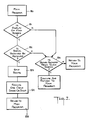
- Fig. 7 illustrates a flow diagram of the operation of the program of the microcomputer 60, in accordance with one embodiment of the invention.
- the program branches from a main program 81, and during the occurrence of the main screen display Fig. 2 , determines at block 82 if a valid control signal has been received from the signal receiver. If a valid signal has been received, an audible signal is emitted, at block 83, the desired function is executed, at block 84, and the subroutine returns to the main program, at block 85. If a control signal was received, instead, from the touch screen, as indicated at block 86, the desired control is executed and control is returned to the main program.
- the remote control transmitter is effective to control the inserter only during the occurrence of the main screen, and during the display of the main screen only a limited number of predetermined functions may be controlled by the remote transmitter.
- this control functions are only the starting, stopping and one-cycling of the inserter.
- commands executed under control of the remote transmitter result in the production of an audible warning.
- the remote transmitted may be conveniently carried by service personnel, for example on their belts.
Abstract
Description
- This invention relates to document inserters that are employed, for example, for the inserting of documents into envelopes for mailing. The invention is in particular directed to a method and apparatus enabling remote control of such inserters.
- Document inserters, of the type to which the present invention is directed, are disclosed, for example, in U.S. Patent No. 4,517,650. Model 8300 Inserter, manufactured by Pitney Bowes Inc., of Stamford CT, is commercially available. Inserters of this type include a number of modules, for example for stacking inserts for insertion in envelopes, and are controlled by a central control system. The control system employs a touch screen for controlling the inserter, the touch screen is capable of displaying a relatively a large number of screen presentations, for example for displaying the machine status and is capable of controlling various set-up and other functions, as well as controlling starting, stopping and single cycling of the machine. In the past it has been considered necessary that all of these functions be centrally performed at the touch screen.
- It has been found that advantages are derived by employing a remote control for certain function of an inserter of the above type, at least under predetermined conditions. For example, it may be desirable to be able to remotely control the inserter only when the screen of the touch screen display displays a specific control function, so that remote control is not possible during other operational functioning the inserter.
- The invention provides a document inserter having a touch control display screen and a control system for controlling the inserter and the display screen.The control system comprises means for enabling a plurality of different displays on the display screen. A portable remote control transmitter is provided for emitting a plurality of control signals, and a receiver is coupled to the control system for receiving the control signals. The control system comprises means for controlling the inserter in response to receipt of the control signals by the receiver, only during a predetermined number, for example, one, of displays on the display screen. The predetermined number is less than all of the plurality of possible display screens.
- The inserter may further comprise a device for providing an audible alarm, in which case the control system comprises means responsive to receipt of a control signal by the signal receiver for energizing the audible alarm device.
- The control signal from the remote transmitter may be limited to control signals for starting, stopping and single-cycling the inserter.
- The invention also provides a method for remotely controlling an inserter that has a touch screen and a control system for controlling the touch screen to show a plurality of different dis plays on the touch screen, and wherein the control system controls the operation of the inserter. The method comprises sending a control signal to the control system from remotely of the inserter, and controlling the inserter in response to the control signal only during the occurrence of a predetermined number of the displays. The predetermined number is less than all of the displays.
- In order that the invention may be more clearly understood, it will now be disclosed in greater detail with reference to the accompanying drawing, wherein:
- Fig. 1 is a perspective view of a multi-station document inserter and including one example of a remote control system in accordance with the invention;
- Fig. 2 is an illustration of the display present on the central control display of the system of Fig. 1;
- Fig. 3 is an illustration of the display on the central control display of the system of Fig. 1 during a continuous run operation;
- Fig. 4 is an illustration of the display on the central control display of the system of Fig. 1 when a fault condition is detected;
- Fig. 5 is an illustration of the display on the central control display of Fig. 1 when the inserter configuration is displayed;
- Fig. 6 is a block diagram of a control system in accordance with the invention; and
- Fig. 7 is a flow diagram illustrating the operation of the system of the invention.
- Fig. 1 is a perspective view of a document inserter 10, for example a Pitney Bowes Type 8300 inserter, as disclosed in U.S. Patent No. 4,517,650, in combination with the present invention. The inserter includes a plurality of serially arranged modules including an envelope feeder station or
module 15 and six document feeder stations, including five feeder modules designated as 14, 16, 18, 20 and 22 and burster-folder station ormodule 24. A computer generated forms feeder 26 feeds continuousform control documents 27 having codedmarks 28 thereon to the burster-folder 24 for separating and folding. The codedmarks 28 on thecontrol documents 27 are sensed by acontrol scanner 29. Thereafter the serially arrangedfeeder stations control document 27 arrives at the respective station, to form a precisely collated stack of documents which is to be transferred to theenvelope feeder 15. - The collated stack of documents is inserted in an envelope at the
envelope station 15. The necessary postage is provided and the envelope is sealed by ameter 31. As desired, the completed envelopes may then be transported to a single ormulti-station level stacker 32. - The
inserter 10 also includes acentral control display 34 which displays status messages and fault signals in human readable form, and further enables the operator to control and change the configuration of theinserter 10 by finger touch switches. Further details of the construction and operation of theinserter 10 which are not necessary to describe here are disclosed in U.S. Patent No. 4,517,650, the disclosure of which is incorporated herein by reference. - As further illustrated in Fig. 1, the system in accordance with a preferred embodiment of the invention includes a hand held
remote transmitter 30, adapted to communicate with the control arrangement of thecentral control display 34. - Advantageously, the central control display 12 is a finger touch display, such as a commercially available Fluke Model 1780A Info Touch Display. The central control display 12 may be of the type disclosed in the European patent (EP-A) No. 102 699 entitled Universal Multi-Station Document Inserter, the entire disclosure of which is incorporated herein by reference to the extent necessary to understand the present invention. As disclosed in the aforementioned European Patent No. 102699, the
central control display 32 is electrically connected to a supervisory control circuit of a multi-station document inserter 10 through a RS232C standard communication line. Thecentral control display 34 provides an operator or user with certain switches which when activated cause theinserter 10 to undergo certain routines and provide displays in human readable form. - As illustrated in Fig. 2, the
central control display 34 is shown with certain information displayed that is displayed upon Power Up. Specifically, the following touch switches are displayed:
Start Machine - For starting the machine operation.
One Cycle - For activating the machine for one cycle of operation.
Continuous Run - For activating the machine for continuous-run operation.
Sequence Start - For sequentially activating one feeder module per cycle. This switch activates the envelope module feeder in time to insert the first collation.
Stop - For stopping the operation of the inserter. Actual cessation of operation can normally occur at only one point in the inserter cycle.
Clear Deck (Sequence Stop) - This switch sequentially deactivates one feeder module per cycle. It also deactivates the envelope feeder after the last collation is inserted, and processes the last inserted collation through postage meter (if applicable) to the stacker.
Change Set-Up - This switch switches to a different display, for example for providing a display of the inserter configuration to enable a change in the inserter operation. - The display screen may also display information enabling the operator to determine:
Operating Mode
Fault Condition (if any)
Piece Count
A maintenance reminder message showing the first power-up after one million cycles. This reminder message may be displayed after each subsequent power-up until canceled by a service technician. - Fig. 3, illustrates a further typical screen, that may be displayed during continuous run operation. It shows the following information:
Operating Mode
Piece Count
Action To Be Taken To Halt Operation - Fig. 4, shows a further screen, that may be displayed upon detection of a fault by the supervisory control circuit of the
document inserter 10. This screen displays the fact that a fault has occurred, and the location of the fault. - Fig. 5 shows a display that may be present when the operator actuates the inserter Change Set Up switch discussed with reference to Fig. 2. This screen shows the following information regarding the configuration of the inserter:
Station Numbers
Type of Feeder per Station Number
Feeder Select Status
Feeder On/Off Status
Assigned Station Number
Line Spacing (scan marks at multiple document feeders) Feed Stop
Feed Count
Mismatch Count
Postage Break
Low Break
High Break - Additionally, Reset, Modify, Reassign, Diagnosis and Reset Piece Count switches may displayed.
- It is of course apparent that the above discussed displays are only a small number of examples of screens that are employed in typical touch screen inserter displays.
- As illustrated in Fig. 6, the hand held
transmitter 30 in accordance with the invention may be comprised of asignal transmitter 50 for transmitting radio oscillations modulated by an encoder 51. The encoding of the encoder is controlled by manually operated switches, such as the START switch, the STOP switch 53 and the ONE-CYCLE switch 54, so that the signals transmitted by thetransmitter 50 are uniquely dependent upon the activation of the switches 52-54. This device may be comprised, for example of an RCS4-1 command system as manufactured by Remtron, Inc. of Oceanside California, 92054. It is of course apparent that other devices may alternatively be employed, similar for example to a conventional garage door opener, and that other remote control arrangements, such as but not limited to, ultrasound, may alternatively be employed. - Still referring to Fig. 6, the central control system of the inserter comprises a microcomputer 60 coupled to the
touch display screen 61 and theinserter 62, for control in the above described manner. Asignal receiver 65, such as a radio receiver, is provided on the inserter, for receiving signals from the transmitter. The receiver may, for example, be located in thedisplay 34 as illustrated in Fig. 1. The receiver and decoder may be comprised of components of the above discussed RCS4-1 command system. The output of the receiver is applied to adecoder 66 for producing outputs selectively dependent upon the depression of the switches 52-54, and this data is output to the microcomputer 60. Accordingly, the microcomputer 60 for controlling theinserter 62 is provided with data corresponding to which, if any, of the switches 52-54 has been depressed. - In addition, in accordance with a further feature of the invention, the microcomputer also controls a
speaker 70 or other device for producing an audible output. - The
remote control transmitter 30 thereby enables an operator or service personnel to control the operation of the inserter, in a limited number of modes, from locations other than at the touch screen itself. This capability has been found to greatly facilitate the setup and servicing of the inserter, since many locations of an inserter of the above type that must be observed during certain operations are too far from the touch screen to permit a single person to both control the machine and observe its operation. - It has further been found that such remote control is advantageously permissible only during the display of certain display screens on the display, for example, only during the occurrence of the main screen display illustrated in Fig. 2. This feature prevents danger to personnel as well as to the inserter, ensures that the signals from the transmitter are processed properly for the desired control of the inserter.
- In accordance with a still further feature of the invention, the microcomputer 60 controls the
speaker 70, upon receipt of a valid control signal from thedecoder 66, to emit a distinctive audible signal, such a three beeps, so that other personnel a warned that the inserter is being operated even though no controller is present at the touch screen itself. - Fig. 7 illustrates a flow diagram of the operation of the program of the microcomputer 60, in accordance with one embodiment of the invention. As illustrated, the program branches from a
main program 81, and during the occurrence of the main screen display Fig. 2 , determines atblock 82 if a valid control signal has been received from the signal receiver. If a valid signal has been received, an audible signal is emitted, atblock 83, the desired function is executed, atblock 84, and the subroutine returns to the main program, atblock 85. If a control signal was received, instead, from the touch screen, as indicated atblock 86, the desired control is executed and control is returned to the main program. - In other words, the remote control transmitter is effective to control the inserter only during the occurrence of the main screen, and during the display of the main screen only a limited number of predetermined functions may be controlled by the remote transmitter. In the preferred embodiment of the invention, this control functions are only the starting, stopping and one-cycling of the inserter. In addition, contrary to operation under control of the touch screen itself, commands executed under control of the remote transmitter result in the production of an audible warning. The remote transmitted may be conveniently carried by service personnel, for example on their belts.
- While the invention has been disclosed and described with reference to a single embodiment, it will be apparent that variations and modification may be made therein without departing from the invention.
Claims (11)
Applications Claiming Priority (2)
| Application Number | Priority Date | Filing Date | Title |
|---|---|---|---|
| US292051 | 1988-12-30 | ||
| US07/292,051 US5027279A (en) | 1988-12-30 | 1988-12-30 | Method and apparatus for remotely controlling a document inserter |
Publications (2)
| Publication Number | Publication Date |
|---|---|
| EP0376467A1 true EP0376467A1 (en) | 1990-07-04 |
| EP0376467B1 EP0376467B1 (en) | 1993-04-28 |
Family
ID=23122974
Family Applications (1)
| Application Number | Title | Priority Date | Filing Date |
|---|---|---|---|
| EP89312082A Expired - Lifetime EP0376467B1 (en) | 1988-12-30 | 1989-11-21 | Method and apparatus for remotely controlling a document inserter |
Country Status (6)
| Country | Link |
|---|---|
| US (1) | US5027279A (en) |
| EP (1) | EP0376467B1 (en) |
| JP (1) | JPH02227300A (en) |
| AU (1) | AU4454789A (en) |
| CA (1) | CA2002116C (en) |
| DE (1) | DE68906255T2 (en) |
Cited By (5)
| Publication number | Priority date | Publication date | Assignee | Title |
|---|---|---|---|---|
| FR2698706A1 (en) * | 1992-11-27 | 1994-06-03 | Neopost Ind | Mail processing system using central control display - provides letter preparation to perform franking, and displays franking values in graphic display zone |
| EP0731425A1 (en) * | 1995-03-07 | 1996-09-11 | Frama Ag | Postage determination device |
| FR2778602A1 (en) * | 1998-05-15 | 1999-11-19 | Aten Cef Sa | Document folder and envelope filler |
| NL1010936C2 (en) * | 1998-12-31 | 2000-07-03 | Neopost Bv | Method and system for generating and finishing documents. |
| WO2001021416A1 (en) * | 1999-09-23 | 2001-03-29 | Alexander Auer | Method and device for the production and packing of documents |
Families Citing this family (14)
| Publication number | Priority date | Publication date | Assignee | Title |
|---|---|---|---|---|
| US5119306A (en) * | 1990-01-02 | 1992-06-02 | Pitney Bowes Inc. | Mail piece weight quality control system and method |
| US5321602A (en) * | 1990-06-04 | 1994-06-14 | Pitney Bowes Inc. | Tutorial control panel |
| JP3050348B2 (en) * | 1992-04-17 | 2000-06-12 | インターナショナル・ビジネス・マシーンズ・コーポレイション | Method and apparatus for user control in a process control system |
| US5448490A (en) * | 1993-03-23 | 1995-09-05 | Pitney Bowes Inc. | System and method for two level real-time control for an inserting machine |
| NL9401155A (en) * | 1994-07-12 | 1996-02-01 | Hadewe Bv | Mail processing system with diagnostic facilities. |
| US6952801B2 (en) * | 1995-06-07 | 2005-10-04 | R.R. Donnelley | Book assembly process and apparatus for variable imaging system |
| US6246993B1 (en) | 1997-10-29 | 2001-06-12 | R. R. Donnelly & Sons Company | Reorder system for use with an electronic printing press |
| AU757375B2 (en) | 1998-10-29 | 2003-02-20 | Pitney-Bowes Inc. | A method and system for selectively replenishing a postage meter on an inserter system |
| US6334119B1 (en) | 1998-11-13 | 2001-12-25 | Pitney Bowes Inc. | Method and system for selectively interacting with a postage meter provided on an inserter system |
| US7278094B1 (en) | 2000-05-03 | 2007-10-02 | R. R. Donnelley & Sons Co. | Variable text processing for an electronic press |
| DE10124371A1 (en) * | 2001-05-18 | 2002-11-21 | Rohde & Schwarz | Measurement unit, especially a signal generator has a number of function units that can be connected in different manners and a control unit that determines their connections and represents them on a graphical display |
| US6885910B2 (en) * | 2003-09-02 | 2005-04-26 | Pitney Bowes Inc. | Mail inserter machine remote control with a scanner |
| US8054294B2 (en) | 2006-03-31 | 2011-11-08 | Sony Corporation | Touch screen remote control system for use in controlling one or more devices |
| US8123223B1 (en) | 2010-10-04 | 2012-02-28 | Andersen & Associates | Document printer and inserter |
Citations (4)
| Publication number | Priority date | Publication date | Assignee | Title |
|---|---|---|---|---|
| EP0102700A2 (en) * | 1982-07-01 | 1984-03-14 | Pitney Bowes, Inc. | User friendly central control display for a multi-station document inserter |
| US4527468A (en) * | 1984-10-29 | 1985-07-09 | Pitney Bowes Inc. | Apparatus for separating multiple webs of documents into discrete documents and forming the discrete documents into predetermined batches |
| WO1988001543A1 (en) * | 1986-09-05 | 1988-03-10 | Opex Corporation | Apparatus for the automated processing of bulk mail and the like |
| US4829443A (en) * | 1987-02-02 | 1989-05-09 | Pitney Bowes Inc. | Insertion machine with computerized postage search and prioritized selection of inserts |
Family Cites Families (5)
| Publication number | Priority date | Publication date | Assignee | Title |
|---|---|---|---|---|
| US3914538A (en) * | 1972-05-16 | 1975-10-21 | Xerox Corp | Facsimile communication system |
| US4547856A (en) * | 1982-07-01 | 1985-10-15 | Pitney Bowes Inc. | Universal multi-station document inserter |
| US4837714A (en) * | 1986-04-18 | 1989-06-06 | Pitney Bowes, Inc. | Methods and apparatus for customizing and testing fully assembled postage meters |
| US4853869A (en) * | 1987-03-13 | 1989-08-01 | Pitney Bowes, Inc. | System and method for processing a letter for bulk mailing |
| US4797832A (en) * | 1987-03-13 | 1989-01-10 | Pitney Bowes Inc. | Letter preparing apparatus |
-
1988
- 1988-12-30 US US07/292,051 patent/US5027279A/en not_active Expired - Lifetime
-
1989
- 1989-11-02 CA CA002002116A patent/CA2002116C/en not_active Expired - Fee Related
- 1989-11-10 AU AU44547/89A patent/AU4454789A/en not_active Abandoned
- 1989-11-21 EP EP89312082A patent/EP0376467B1/en not_active Expired - Lifetime
- 1989-11-21 DE DE8989312082T patent/DE68906255T2/en not_active Expired - Fee Related
- 1989-12-11 JP JP1321253A patent/JPH02227300A/en active Pending
Patent Citations (4)
| Publication number | Priority date | Publication date | Assignee | Title |
|---|---|---|---|---|
| EP0102700A2 (en) * | 1982-07-01 | 1984-03-14 | Pitney Bowes, Inc. | User friendly central control display for a multi-station document inserter |
| US4527468A (en) * | 1984-10-29 | 1985-07-09 | Pitney Bowes Inc. | Apparatus for separating multiple webs of documents into discrete documents and forming the discrete documents into predetermined batches |
| WO1988001543A1 (en) * | 1986-09-05 | 1988-03-10 | Opex Corporation | Apparatus for the automated processing of bulk mail and the like |
| US4829443A (en) * | 1987-02-02 | 1989-05-09 | Pitney Bowes Inc. | Insertion machine with computerized postage search and prioritized selection of inserts |
Cited By (7)
| Publication number | Priority date | Publication date | Assignee | Title |
|---|---|---|---|---|
| FR2698706A1 (en) * | 1992-11-27 | 1994-06-03 | Neopost Ind | Mail processing system using central control display - provides letter preparation to perform franking, and displays franking values in graphic display zone |
| EP0731425A1 (en) * | 1995-03-07 | 1996-09-11 | Frama Ag | Postage determination device |
| FR2778602A1 (en) * | 1998-05-15 | 1999-11-19 | Aten Cef Sa | Document folder and envelope filler |
| NL1010936C2 (en) * | 1998-12-31 | 2000-07-03 | Neopost Bv | Method and system for generating and finishing documents. |
| EP1016468A1 (en) * | 1998-12-31 | 2000-07-05 | Neopost B.V. | Method and system for generating and finishing documents |
| US7333231B2 (en) | 1998-12-31 | 2008-02-19 | Neopost B.V. | Method and system for generating and finishing documents |
| WO2001021416A1 (en) * | 1999-09-23 | 2001-03-29 | Alexander Auer | Method and device for the production and packing of documents |
Also Published As
| Publication number | Publication date |
|---|---|
| CA2002116A1 (en) | 1990-06-30 |
| DE68906255T2 (en) | 1993-08-12 |
| EP0376467B1 (en) | 1993-04-28 |
| AU4454789A (en) | 1990-07-05 |
| CA2002116C (en) | 1998-08-04 |
| DE68906255D1 (en) | 1993-06-03 |
| JPH02227300A (en) | 1990-09-10 |
| US5027279A (en) | 1991-06-25 |
Similar Documents
| Publication | Publication Date | Title |
|---|---|---|
| EP0376467A1 (en) | Method and apparatus for remotely controlling a document inserter | |
| CA1209212A (en) | Selective call paging and priority signalling system | |
| US4547856A (en) | Universal multi-station document inserter | |
| EP0208342B1 (en) | Office automation system | |
| EP0180400B1 (en) | An inserter system | |
| EP0376738B2 (en) | Dual mode communication | |
| USRE35449E (en) | Remote 2-way transmission audience polling and response system | |
| AU631831B2 (en) | Asynchronous multiple module control and communication protocol | |
| EP0180401B1 (en) | Document inserter systems | |
| US4497040A (en) | Method and apparatus for customizing a multi-station document-inserter | |
| WO1987001002A1 (en) | Electronic information dissemination system | |
| AU630905B2 (en) | Auto-translation system for generating messages in a modular machine | |
| US4517650A (en) | Feeder interface circuit for universal multi-station document inserter | |
| EP0102700A2 (en) | User friendly central control display for a multi-station document inserter | |
| JPH02288901A (en) | Multiprocessing station message communication system | |
| JPH02289399A (en) | Device for developing and controlling record of document arran gement | |
| CA2006018C (en) | Asynchronous rejection in an inserter | |
| US4970654A (en) | Asynchronous queuing and collation passage in an inserter | |
| EP0377330B1 (en) | Multiple material processings system start-up | |
| EP0106153B1 (en) | A repeat control apparatus for a serial interface keyboard apparatus | |
| US7277772B2 (en) | Mail inserter machine remote control with a scanner | |
| US5321602A (en) | Tutorial control panel | |
| CN1251698A (en) | Method for transceiver to select channel | |
| EP0330514B1 (en) | Battery powered radio devices having a battery saving function | |
| EP0701335A2 (en) | Wireless communication system and station for use therein |
Legal Events
| Date | Code | Title | Description |
|---|---|---|---|
| PUAI | Public reference made under article 153(3) epc to a published international application that has entered the european phase |
Free format text: ORIGINAL CODE: 0009012 |
|
| AK | Designated contracting states |
Kind code of ref document: A1 Designated state(s): BE CH DE FR GB IT LI NL SE |
|
| 17P | Request for examination filed |
Effective date: 19901219 |
|
| 17Q | First examination report despatched |
Effective date: 19920903 |
|
| GRAA | (expected) grant |
Free format text: ORIGINAL CODE: 0009210 |
|
| AK | Designated contracting states |
Kind code of ref document: B1 Designated state(s): BE CH DE FR GB IT LI NL SE |
|
| PG25 | Lapsed in a contracting state [announced via postgrant information from national office to epo] |
Ref country code: NL Effective date: 19930428 Ref country code: SE Effective date: 19930428 Ref country code: BE Effective date: 19930428 Ref country code: IT Free format text: LAPSE BECAUSE OF FAILURE TO SUBMIT A TRANSLATION OF THE DESCRIPTION OR TO PAY THE FEE WITHIN THE PRE;WARNING: LAPSES OF ITALIAN PATENTS WITH EFFECTIVE DATE BEFORE 2007 MAY HAVE OCCURRED AT ANY TIME BEFORE 2007. THE CORRECT EFFECTIVE DATE MAY BE DIFFERENT FROM THE ONE RECORDED.SCRIBED TIME-LIMIT Effective date: 19930428 |
|
| REF | Corresponds to: |
Ref document number: 68906255 Country of ref document: DE Date of ref document: 19930603 |
|
| ET | Fr: translation filed | ||
| NLV1 | Nl: lapsed or annulled due to failure to fulfill the requirements of art. 29p and 29m of the patents act | ||
| PLBI | Opposition filed |
Free format text: ORIGINAL CODE: 0009260 |
|
| 26 | Opposition filed |
Opponent name: NEOPOST LTD Effective date: 19940124 |
|
| APAC | Appeal dossier modified |
Free format text: ORIGINAL CODE: EPIDOS NOAPO |
|
| PLBO | Opposition rejected |
Free format text: ORIGINAL CODE: EPIDOS REJO |
|
| PLBN | Opposition rejected |
Free format text: ORIGINAL CODE: 0009273 |
|
| STAA | Information on the status of an ep patent application or granted ep patent |
Free format text: STATUS: OPPOSITION REJECTED |
|
| 27O | Opposition rejected |
Effective date: 19981022 |
|
| REG | Reference to a national code |
Ref country code: GB Ref legal event code: IF02 |
|
| APAH | Appeal reference modified |
Free format text: ORIGINAL CODE: EPIDOSCREFNO |
|
| PGFP | Annual fee paid to national office [announced via postgrant information from national office to epo] |
Ref country code: GB Payment date: 20051116 Year of fee payment: 17 |
|
| PGFP | Annual fee paid to national office [announced via postgrant information from national office to epo] |
Ref country code: FR Payment date: 20051117 Year of fee payment: 17 |
|
| PGFP | Annual fee paid to national office [announced via postgrant information from national office to epo] |
Ref country code: CH Payment date: 20051125 Year of fee payment: 17 |
|
| PGFP | Annual fee paid to national office [announced via postgrant information from national office to epo] |
Ref country code: DE Payment date: 20060102 Year of fee payment: 17 |
|
| PG25 | Lapsed in a contracting state [announced via postgrant information from national office to epo] |
Ref country code: CH Free format text: LAPSE BECAUSE OF NON-PAYMENT OF DUE FEES Effective date: 20061130 Ref country code: LI Free format text: LAPSE BECAUSE OF NON-PAYMENT OF DUE FEES Effective date: 20061130 |
|
| PG25 | Lapsed in a contracting state [announced via postgrant information from national office to epo] |
Ref country code: DE Free format text: LAPSE BECAUSE OF NON-PAYMENT OF DUE FEES Effective date: 20070601 |
|
| REG | Reference to a national code |
Ref country code: CH Ref legal event code: PL |
|
| GBPC | Gb: european patent ceased through non-payment of renewal fee |
Effective date: 20061121 |
|
| REG | Reference to a national code |
Ref country code: FR Ref legal event code: ST Effective date: 20070731 |
|
| PG25 | Lapsed in a contracting state [announced via postgrant information from national office to epo] |
Ref country code: GB Free format text: LAPSE BECAUSE OF NON-PAYMENT OF DUE FEES Effective date: 20061121 |
|
| PG25 | Lapsed in a contracting state [announced via postgrant information from national office to epo] |
Ref country code: FR Free format text: LAPSE BECAUSE OF NON-PAYMENT OF DUE FEES Effective date: 20061130 |