EP0376463B1 - Code break mechanism for stacking apparatus - Google Patents
Code break mechanism for stacking apparatus Download PDFInfo
- Publication number
- EP0376463B1 EP0376463B1 EP19890311980 EP89311980A EP0376463B1 EP 0376463 B1 EP0376463 B1 EP 0376463B1 EP 19890311980 EP19890311980 EP 19890311980 EP 89311980 A EP89311980 A EP 89311980A EP 0376463 B1 EP0376463 B1 EP 0376463B1
- Authority
- EP
- European Patent Office
- Prior art keywords
- wall
- deck
- housing
- stack
- deflector plate
- Prior art date
- Legal status (The legal status is an assumption and is not a legal conclusion. Google has not performed a legal analysis and makes no representation as to the accuracy of the status listed.)
- Expired - Lifetime
Links
- 230000007246 mechanism Effects 0.000 title claims description 8
- 238000006073 displacement reaction Methods 0.000 claims description 5
- 230000004913 activation Effects 0.000 claims description 3
- 230000004044 response Effects 0.000 claims description 2
- 230000000007 visual effect Effects 0.000 claims description 2
- 230000003213 activating effect Effects 0.000 claims 1
- 230000000712 assembly Effects 0.000 description 4
- 238000000429 assembly Methods 0.000 description 4
- 238000004891 communication Methods 0.000 description 3
- 230000008859 change Effects 0.000 description 1
- 230000008878 coupling Effects 0.000 description 1
- 238000010168 coupling process Methods 0.000 description 1
- 238000005859 coupling reaction Methods 0.000 description 1
- 230000013011 mating Effects 0.000 description 1
- 238000000034 method Methods 0.000 description 1
- 238000004806 packaging method and process Methods 0.000 description 1
Images


Classifications
-
- B—PERFORMING OPERATIONS; TRANSPORTING
- B65—CONVEYING; PACKING; STORING; HANDLING THIN OR FILAMENTARY MATERIAL
- B65H—HANDLING THIN OR FILAMENTARY MATERIAL, e.g. SHEETS, WEBS, CABLES
- B65H33/00—Forming counted batches in delivery pile or stream of articles
- B65H33/06—Forming counted batches in delivery pile or stream of articles by displacing articles to define batches
- B65H33/10—Displacing the end articles of a batch
-
- B—PERFORMING OPERATIONS; TRANSPORTING
- B65—CONVEYING; PACKING; STORING; HANDLING THIN OR FILAMENTARY MATERIAL
- B65H—HANDLING THIN OR FILAMENTARY MATERIAL, e.g. SHEETS, WEBS, CABLES
- B65H2301/00—Handling processes for sheets or webs
- B65H2301/40—Type of handling process
- B65H2301/42—Piling, depiling, handling piles
- B65H2301/421—Forming a pile
- B65H2301/4214—Forming a pile of articles on edge
- B65H2301/42144—Forming a pile of articles on edge by erecting articles from horizontal transport flushing with the supporting surface of the pile
-
- B—PERFORMING OPERATIONS; TRANSPORTING
- B65—CONVEYING; PACKING; STORING; HANDLING THIN OR FILAMENTARY MATERIAL
- B65H—HANDLING THIN OR FILAMENTARY MATERIAL, e.g. SHEETS, WEBS, CABLES
- B65H2701/00—Handled material; Storage means
- B65H2701/10—Handled articles or webs
- B65H2701/19—Specific article or web
- B65H2701/1916—Envelopes and articles of mail
Definitions
- This invention relates to a code break mechanism for a stacking apparatus receiving a stream of articles, and more particularly to a code breakat for producing discontinuities in the article stream in accordance with a selected parameter change in the article stream.
- the last process step is the collection of processed articles.
- a power stacker may be employed to collect envelopes ejected from a mailing machine.
- the power stacker receives the envelopes in seriatim and in a uniform manner and stacks the envelopes.
- An operator periodically removes the accumulated envelope stack from the stacker for packaging in preparation for subsequent deposit with a mail forwarding agent, e.g. a National Postal Authority.
- Mail forwarding agents offer to the mailers special postage discount rates for mail which is presorted, for example, by an appropriate standard address code. Therefore, where the mail is processed in a presorted manner, for example, according to such a code, it would be advantageous to the operator for the power stacker to include a means for visually marking address code changes or breaks within the stacker received mail stream.
- One suitable form of power stacker includes a deck fixably mounted to and supported by a housing such that the deck is positioned at a 15° rearward reclined angle.
- a registration wall is fixably mounted to the housing and extends generally perpendicular relative to the deck.
- a stack wall is mounted for sliding movement relative to the housing at one end.
- a stacker apparatus which includes a code break mechanism has been proposed in German Patent Application No. DE-A-1 254 950. However, this arrangement does not have a registration wall and apparently can only accept articles such as letters which are presented to it in a substantially vertical orientation.
- a different kind of stacker apparatus is shown by Faeber in U.S. Patent No. US-A-2 843 378. This is particularly directed to stacking signatures from a printing press in such a way that they stand substantially vertical. Faeber aims to prevent smearing or tearing of the signatures, and, for this purpose, a special design of stacking station is provided.
- German Patentschrift No. 426 209 (1926) there is disclosed an arrangement having a simple pusher for thrusting a group of envelopes sideways, at predetermined times during the operation of the machine.
- the envelopes are tilted towards the vertical after being fed in.
- No registration wall, no spring biassed rear wall, and no helical threaded hubs are to be seen in this German Patent.
- an apparatus for collecting delivered articles comprising: a power stacker having a support housing, a deck supported by said housing, a registration wall fixed to said housing and extending generally perpendicular to said deck, stack wall slidably mounted to said housing at one end of said deck, said stack wall being slidably mounted to said housing such that said stack wall can be horizontally displaced outwardly from said deck, means for causing said delivered articles to be forcibly stacked against said stack wall, support means slidably mounted to said housing for providing article support between said deck and said displaced stack wall and biassing means for providing a counter return force to said stack wall; characterised by the fact that:
- the drive means is a rotary solenoid whose activation is caused by a motor controller in response to a code break lottor being discharged from a feed device.
- the deflector means may further comprise biassing means for biassing said deflector plate in said first position, said biassing means acting on said linking means.
- An apparatus comprises a deflector plate pivotally mounted within a mating opening in the registration wall.
- the deflector plate in a first or normal position is located coplanar with the registration surface of the registration wall.
- a solenoid responding to a control signal from a controller, is fixed in the housing and communicates with the deflector plate through a linkage in such a way that actuation of the solenoid causes pivotal displacement of the deflector plate from the first position to the second position.
- the deflector plate When the deflector plate is positioned in the second position, it laterally deflects the next-arriving envelope.
- the code break-indicating envelope is thereby laterally misaligned with respect to the envelope stack allowing an operator to visually observe code breaks in the stack.
- a suitable power stacker generally indicated at 11, comprises a base or support housing 12 having a base 13.
- a plurality of vertically extending support posts 15 and 17 are fixed to base 13 at one end.
- the base 13 also has fixed thereto, in vertical alignment, a forward wall 21 and a parallel rear wall 23 transversely spaced therefrom.
- End walls 25 and 27 are fixed to the base 13 in spaced relationship and at their ends to respective walls 21 and 23.
- a deck 31 is fixed to walls 21, 23, 25 and 27 and along its underside to the support posts 15 and 17, such that the deck assumes an inclined position, front to rear (herein called a reclined position), of approximately 15° (fifteen degrees) from the horizontal.
- the deck 31 contains a plurality of slots 33, 35 and 37.
- Fixed to the underside of the deck 31 at the receiving or forward end are first and second adjustable tension brace assemblies 41 and 43, Fig. 3. Also fixed to the underside of the deck 31 at the other end are braces 45. Each brace 45 is longitudinally aligned to a respective brace assembly 41 or 43.
- a motor mount 48 having a motor 49 mounted thereto, is fixed to the underside of the deck 31.
- the motor 49 includes an output shaft 51 having a pulley wheel 52 carried by the output shaft 51.
- a shaft 53 carrying three friction wheels, one shown at 55, Fig. 2, is rotatively mounted in the braces 45. The friction wheels are respectively radially aligned to the first slots 33, 35 and 37, Fig. 3.
- a second shaft 63 is rotatably mounted in the brace assemblies 41 and 42. The shaft 63 carries three friction wheels, one shown at 65. These three friction wheels are radially aligned to the respective second slots 33, 35 and 37, Fig. 3. Endless belts 71, 73 and 74 extend around the respective friction wheel pairs.
- the shaft 53 further includes a pulley wheel 81 which is in communication by an endless belt 83 with the motor 49 for providing a drive to the shaft 53.
- the shaft 53 further carries bevel gears 85 and 87 fixed thereto in axially spaced relationship.
- the rear wall 23 has an aperture 89 through which an end portion of the shaft 53 extends.
- the shaft 53 has fixed thereto a pulley 91.
- End wall 25 has formed thereon a plurality of studs 94 and 93 through which extends a respective shaft 95 and 97 seated at one end in the end wall 25.
- Rotatively mounted around the other end of shafts 95 and 97 are respective threaded hubs 101 and 103.
- the threaded hubs 101 and 103 are mounted such that they partially extend into respective appertures, one seen at 104, formed into the deck 31.
- Bevel gears 92 and 93 are rotatively mounted around the respective shafts 95 and 97 in driving communication with the respective threaded hubs 101 and 103.
- the bevel gears 92 and 93 are in constant mesh with respective bevel gears 85 and 87.
- a stack wall 111 has a formed facing surface 113 abutting to the outer face of end wall 25 leading upwardly to a reclined surface 115.
- a plurality of guide rods 117, 119 and 121 are fixed at one end to the facing surface of the stack wall 111.
- the guide rods 117, 119 and 121 extend slidably through respective apertures in the end wall and are slidably received by respective guide tabs 123, 125 and 127.
- the guide tabs 123, 125 and 127 are fixed to the underside of the deck 31.
- slide rail assemblies 141 and 143 have rail portions fixed to the respective side walls 21 and 23. Another rail portion of rail assemblies 141 and 143 is fixed at one end to the facing surface 113 of the stack wall 111 such that the stack wall 111 can be slidably displaced.
- a registration wall 145 is mounted longitudinally along the rear wall 23 and oriented generally perpendicular to the deck.
- the registration wall 145 includes a recess 147 angled generally perpendicular to the reclined surface 115 of stack wall 111.
- a brace 149 is fixed to the back surface of the registration wall 145.
- the brace 149 includes a shaft 151 rotatably mounted therein such that the shaft 151 extends generally perpendicular to the reclined surface 115 of the stack wall 111.
- a pulley 153 is mounted on the shaft 151.
- An endless belt 155 runs round the pulley 153 and is in driving relationship with the pulley 91 mounted shaft 63.
- a threaded hub 157 is fixed on the shaft 151.
- the registration wall 145 further includes a slot 160.
- a yoke 165 is pivotally mounted in slot 160 to the registration wall 145.
- the yoke 165 carries a yoke wheel 167 rotatively mounted between the forks of the yoke 165.
- the yoke 165 is adjustably mounted in slot 160 such that the yoke wheel rests on the deck 31.
- Also fixably mounted to the back of the registration wall 145 is a guide rod 169 which extends slidably through a slide member 169A fixably mounted to the registration wall 145 and pivotally mounted at one end to the stack wall 111.
- a return spring assembly 166 has one end of its flex strip 168 fixably mounted to the stack wall 111.
- a second return spring assembly 170 is fixably mounted to base 13 having one end of it flex strip 172 fixably mounted to the stack wall 111.
- the code break mechanism generally indicated as 200, includes a deflector plate 202 pivotally mounted in a matting opening 204 in the registration wall 145.
- a bracket 201 is fixably mounted to the back face of the registration wall 145.
- Pivotally mounted to the bracket 201 is a generally L-shaped link 206 having a first slot 208 and a second slot 210.
- a pin 212 is formed to the back face of the deflector plate 202 such that the pin 212 is captured in the slot 208 of the link 206.
- a bracket 214 is fixably mounted to the underside of the deck 31 and fixably supports a rotary solenoid 216.
- the output shaft 218 of the rotary solenoid 216 has fixably mounted thereto to one end of a link 220.
- the link 220 extends through a aperture 222 in the rear wall 23 and has a slot 224 formed in its other end.
- a second bracket 226 is fixably mounted to the rear wall 23.
- Slidably mounted through the brackets 201 and 226 is a link 228 having a hub 239 formed at one end slidably captured in slot 210 of link 206 and at the other end of link 228 a formed pin 232 is slidably captured in slot 224 of link 220.
- the link 228 includes a coupling 234.
- a spring 236 is coiled around the link 228 between the stop rim 234 and the bracket 201.
- a suitable motor controller 171 is in electrical communication through line 173 with a envelope feed device 175, for example, a mailing machine, and through line 177 with the motor 49 and rotary solenoid 216 of the power stacker 12.
- the motor controller 171 synchronously controls the operating speed of the power stacker 12, rotary solenoid 216 and the feed device 175 such that envelopes, for example, 5 inch envelope delivered by the feed device are received by the power stacker in a shingled fashion with approximately a .75 inch spacing between the leading edge of successive envelopes.
- the envelopes are transported by the belts 55, 57 and 59, which are under the drive influence of motor 49 through belt 83 and shaft 63, under the yoke roller 167 such that the leading edge of the lead envelopes engages the stack wall facing 115 and is caused to assume a generally vertical position against the stack wall.
- the subsequent envelopes are caused to assume a generally parallel orientation relative to the lead envelope.
- the positioning of envelopes is assisted by the edge engagement of the envelopes with the threaded hubs 101, 103 and 157.
- the rotary solenoid 216 rotatively displaces link 220 in the direction of arrow A.
- the displacement of link 220 is transmitted by link 228 to cause link 206 to pivotally displace.
- the displacement of link 206 causes the deflector plate 202 to pivotally displace from a first position coplanar with the registration wall 145 to a second position whereupon the deflector plate 202 encounters the code break envelope in route.
- the code break envelope is consequentially displaced laterally relative to the other stacker received envelopes.
Landscapes
- Forming Counted Batches (AREA)
- Pile Receivers (AREA)
Description
- This invention relates to a code break mechanism for a stacking apparatus receiving a stream of articles, and more particularly to a code break mecanism for producing discontinuities in the article stream in accordance with a selected parameter change in the article stream.
- In article processing systems, generally the last process step is the collection of processed articles. For example, in a conventional mail processing system a power stacker may be employed to collect envelopes ejected from a mailing machine. Generally, the power stacker receives the envelopes in seriatim and in a uniform manner and stacks the envelopes. An operator periodically removes the accumulated envelope stack from the stacker for packaging in preparation for subsequent deposit with a mail forwarding agent, e.g. a National Postal Authority.
- Mail forwarding agents offer to the mailers special postage discount rates for mail which is presorted, for example, by an appropriate standard address code. Therefore, where the mail is processed in a presorted manner, for example, according to such a code, it would be advantageous to the operator for the power stacker to include a means for visually marking address code changes or breaks within the stacker received mail stream.
- It is an aim of the present invention to present a code break mechanism particularly suited for employment in a power stacker.
- One suitable form of power stacker includes a deck fixably mounted to and supported by a housing such that the deck is positioned at a 15° rearward reclined angle. A registration wall is fixably mounted to the housing and extends generally perpendicular relative to the deck. A stack wall is mounted for sliding movement relative to the housing at one end.
- A stacker apparatus which includes a code break mechanism has been proposed in German Patent Application No. DE-A-1 254 950. However, this arrangement does not have a registration wall and apparently can only accept articles such as letters which are presented to it in a substantially vertical orientation. A different kind of stacker apparatus is shown by Faeber in U.S. Patent No. US-A-2 843 378. This is particularly directed to stacking signatures from a printing press in such a way that they stand substantially vertical. Faeber aims to prevent smearing or tearing of the signatures, and, for this purpose, a special design of stacking station is provided.
- In German Patentschrift No. 426 209 (1926) there is disclosed an arrangement having a simple pusher for thrusting a group of envelopes sideways, at predetermined times during the operation of the machine. The envelopes are tilted towards the vertical after being fed in. No registration wall, no spring biassed rear wall, and no helical threaded hubs are to be seen in this German Patent.
- According to the present invention, there is provided an apparatus for collecting delivered articles, comprising:
a power stacker having a support housing, a deck supported by said housing, a registration wall fixed to said housing and extending generally perpendicular to said deck, stack wall slidably mounted to said housing at one end of said deck, said stack wall being slidably mounted to said housing such that said stack wall can be horizontally displaced outwardly from said deck, means for causing said delivered articles to be forcibly stacked against said stack wall, support means slidably mounted to said housing for providing article support between said deck and said displaced stack wall and biassing means for providing a counter return force to said stack wall; characterised by the fact that: - (a) the registration wall is fixed to the housing and extending generally perpendicular to the deck, the stack wall having a reclined surface extending generally upwardly from said deck;
- (b) a code break mechanism has a deflector means for encountering a selected one of said articles and causing said selected article to be stacked by said power stacker such that said selected article represents a visual discontinuity relative to said articles stacked by said power stacker;
- (c) said deflector means has a deflector plate pivotally mounted in an opening in said registration wall, and drive means for causing said deflector plate to be selectively positionable from a first position coplanar with said registration wall to a second position pivotally displaced from said registration wall; and
- (d) said drive means has a rotatable output shaft, a first link fixed to one end of said output shaft, and a linking means for connecting said other end of said first link with said deflector plate in such a manner that pivotal displacement of said first link causes said deflector plate to move either to said first or said second position.
- In a preferred embodiment of the invention, the drive means is a rotary solenoid whose activation is caused by a motor controller in response to a code break lottor being discharged from a feed device.
- The deflector means may further comprise biassing means for biassing said deflector plate in said first position, said biassing means acting on said linking means.
- An apparatus according to an embodiment of the invention comprises a deflector plate pivotally mounted within a mating opening in the registration wall. The deflector plate in a first or normal position is located coplanar with the registration surface of the registration wall. A solenoid, responding to a control signal from a controller, is fixed in the housing and communicates with the deflector plate through a linkage in such a way that actuation of the solenoid causes pivotal displacement of the deflector plate from the first position to the second position. When the deflector plate is positioned in the second position, it laterally deflects the next-arriving envelope. The code break-indicating envelope is thereby laterally misaligned with respect to the envelope stack allowing an operator to visually observe code breaks in the stack.
- The invention will be better understood from the following non-limiting description of an example thereof given with reference to the accompanying drawings, in which:-
- Fig. 1 is a partial side view of a power stacker usable in accordance with an example of the present invention;
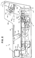
- Fig. 2 is a sectioned side view of the power stacker;
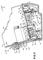
- Fig. 3 is a sectioned end view of the power stacker of Fig. 1;
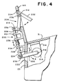
- Fig. 4 is an end view of a code break mechanism in accordance with an example of the present invention; and
- Fig. 5 is a schematic view of a motor control for said power stacker.
- Referring to Figs. 1 and 2, one example of a suitable power stacker, generally indicated at 11, comprises a base or
support housing 12 having abase 13. A plurality of vertically extendingsupport posts 15 and 17 (refer to Fig. 3) are fixed tobase 13 at one end. Thebase 13 also has fixed thereto, in vertical alignment, aforward wall 21 and a parallelrear wall 23 transversely spaced therefrom.End walls base 13 in spaced relationship and at their ends torespective walls - A
deck 31 is fixed towalls support posts deck 31 contains a plurality ofslots deck 31 at the receiving or forward end are first and second adjustable tension brace assemblies 41 and 43, Fig. 3. Also fixed to the underside of thedeck 31 at the other end arebraces 45. Eachbrace 45 is longitudinally aligned to arespective brace assembly - A
motor mount 48, having amotor 49 mounted thereto, is fixed to the underside of thedeck 31. Themotor 49 includes anoutput shaft 51 having apulley wheel 52 carried by theoutput shaft 51. Ashaft 53 carrying three friction wheels, one shown at 55, Fig. 2, is rotatively mounted in thebraces 45. The friction wheels are respectively radially aligned to thefirst slots second shaft 63 is rotatably mounted in thebrace assemblies 41 and 42. Theshaft 63 carries three friction wheels, one shown at 65. These three friction wheels are radially aligned to the respectivesecond slots Endless belts - The
shaft 53 further includes apulley wheel 81 which is in communication by anendless belt 83 with themotor 49 for providing a drive to theshaft 53. Theshaft 53 further carriesbevel gears rear wall 23 has anaperture 89 through which an end portion of theshaft 53 extends. Theshaft 53 has fixed thereto apulley 91. -
End wall 25 has formed thereon a plurality ofstuds 94 and 93 through which extends arespective shaft 95 and 97 seated at one end in theend wall 25. Rotatively mounted around the other end ofshafts 95 and 97 are respective threadedhubs 101 and 103. The threadedhubs 101 and 103 are mounted such that they partially extend into respective appertures, one seen at 104, formed into thedeck 31.Bevel gears respective shafts 95 and 97 in driving communication with the respective threadedhubs 101 and 103. The bevel gears 92 and 93 are in constant mesh withrespective bevel gears - A stack wall 111 has a formed facing
surface 113 abutting to the outer face ofend wall 25 leading upwardly to a reclinedsurface 115. A plurality ofguide rods guide rods respective guide tabs guide tabs deck 31. Referring to Fig. 3,slide rail assemblies respective side walls rail assemblies surface 113 of the stack wall 111 such that the stack wall 111 can be slidably displaced. - Referring to Fig. 2, a
registration wall 145 is mounted longitudinally along therear wall 23 and oriented generally perpendicular to the deck. Theregistration wall 145 includes arecess 147 angled generally perpendicular to the reclinedsurface 115 of stack wall 111. Abrace 149 is fixed to the back surface of theregistration wall 145. Thebrace 149 includes ashaft 151 rotatably mounted therein such that theshaft 151 extends generally perpendicular to the reclinedsurface 115 of the stack wall 111. Apulley 153 is mounted on theshaft 151. Anendless belt 155 runs round thepulley 153 and is in driving relationship with thepulley 91 mountedshaft 63. A threadedhub 157 is fixed on theshaft 151. - The
registration wall 145 further includes aslot 160. Ayoke 165 is pivotally mounted inslot 160 to theregistration wall 145. Theyoke 165 carries ayoke wheel 167 rotatively mounted between the forks of theyoke 165. Theyoke 165 is adjustably mounted inslot 160 such that the yoke wheel rests on thedeck 31. Also fixably mounted to the back of theregistration wall 145 is aguide rod 169 which extends slidably through aslide member 169A fixably mounted to theregistration wall 145 and pivotally mounted at one end to the stack wall 111. Areturn spring assembly 166 has one end of itsflex strip 168 fixably mounted to the stack wall 111. In like manner a secondreturn spring assembly 170 is fixably mounted tobase 13 having one end of itflex strip 172 fixably mounted to the stack wall 111. - Referring to Fig. 4, the code break mechanism, generally indicated as 200, includes a
deflector plate 202 pivotally mounted in amatting opening 204 in theregistration wall 145. Abracket 201 is fixably mounted to the back face of theregistration wall 145. Pivotally mounted to thebracket 201 is a generally L-shapedlink 206 having afirst slot 208 and asecond slot 210. Apin 212 is formed to the back face of thedeflector plate 202 such that thepin 212 is captured in theslot 208 of thelink 206. - A
bracket 214 is fixably mounted to the underside of thedeck 31 and fixably supports arotary solenoid 216. Theoutput shaft 218 of therotary solenoid 216 has fixably mounted thereto to one end of alink 220. Thelink 220 extends through aaperture 222 in therear wall 23 and has aslot 224 formed in its other end. Asecond bracket 226 is fixably mounted to therear wall 23. Slidably mounted through thebrackets link 228 having ahub 239 formed at one end slidably captured inslot 210 oflink 206 and at the other end of link 228 a formedpin 232 is slidably captured inslot 224 oflink 220. Thelink 228 includes acoupling 234. Aspring 236 is coiled around thelink 228 between thestop rim 234 and thebracket 201. - Referring further to Fig. 5, in operation, a
suitable motor controller 171 is in electrical communication throughline 173 with aenvelope feed device 175, for example, a mailing machine, and throughline 177 with themotor 49 androtary solenoid 216 of thepower stacker 12. Themotor controller 171 synchronously controls the operating speed of thepower stacker 12,rotary solenoid 216 and thefeed device 175 such that envelopes, for example, 5 inch envelope delivered by the feed device are received by the power stacker in a shingled fashion with approximately a .75 inch spacing between the leading edge of successive envelopes. The envelopes are transported by thebelts 55, 57 and 59, which are under the drive influence ofmotor 49 throughbelt 83 andshaft 63, under theyoke roller 167 such that the leading edge of the lead envelopes engages the stack wall facing 115 and is caused to assume a generally vertical position against the stack wall. The subsequent envelopes are caused to assume a generally parallel orientation relative to the lead envelope. The positioning of envelopes is assisted by the edge engagement of the envelopes with the threadedhubs - Upon activation by the
motor controller 171 occasioned by the presence of a code break letter being discharged from thefeed device 175, therotary solenoid 216 rotatively displaces link 220 in the direction of arrow A. The displacement oflink 220 is transmitted bylink 228 to causelink 206 to pivotally displace. The displacement oflink 206 causes thedeflector plate 202 to pivotally displace from a first position coplanar with theregistration wall 145 to a second position whereupon thedeflector plate 202 encounters the code break envelope in route. The code break envelope is consequentially displaced laterally relative to the other stacker received envelopes. - As the envelopes are caused to vertically stack, edge engagement of the envelopes with the threaded
hubs rods - The foregoing particular description is of the preferred embodiment of the present invention and should not be viewed as limiting the invention.
Claims (4)
- An apparatus for collecting delivered articles, comprising:
a power stacker (11) having a support housing (12), a deck (31) supported by said housing, a registration wall (145) fixed to said housing and extending generally perpendicular to said deck (31), a stack wall (111) slidably mounted to said housing at one end of said deck, said stack wall being slidably mounted to said housing such that said stack wall can be horizontally displaced outwardly from said deck, means for causing said delivered articles to be forcibly stacked against said stack wall, support means slidably mounted to said housing (12) for providing article support between said deck and said displaced stack wall and biassing means for providing a counter return force to said stack wall; characterised by the fact that:(a) the registration wall (145) is fixed to the housing (12) and extending generally perpendicular to the deck (31), the stack wall (111) having a reclined surface (115) extending generally upwardly from said deck (31);(b) a code break mechanism (200) has a deflector means (202-212) for encountering a selected one of said articles and causing said selected article to be stacked by said power stacker (11) such that said selected article represents a visual discontinuity relative to said articles stacked by said power stacker;(c) said deflector means has a deflector plate (202) pivotally mounted in an opening (204) in said registration wall (145), and drive means (216) for causing said deflector plate (202) to be selectively positionable from a first position coplanar with said registration wall to a second position pivotally displaced from said registration wall; and(d) said drive means (216) has a rotatable output shaft (218), a first link (220) fixed to one end of said output shaft, and a linking means (228) for connecting said other end of said first link (220) with said deflector plate in such a manner that pivotal displacement of said first link causes said deflector plate to move either to said first or second position. - An apparatus according to claim 1 in which the drive means (216) is a rotary solenoid whose activation is caused by a motor controller (171) in response to a code break letter being discharged from a feed device (175).
- An apparatus as claimed in claim 1 or 2, wherein said deflector means (200-212) further comprises biassing means (236) for biassing said deflector plate in said first position, said biassing means acting on said linking means (228,234).
- An apparatus as claimed in claims 1 or 3, further comprising control means (171) for selectively activating said code break meachanism (200).
Applications Claiming Priority (2)
| Application Number | Priority Date | Filing Date | Title |
|---|---|---|---|
| US29148488A | 1988-12-28 | 1988-12-28 | |
| US291484 | 1988-12-28 |
Publications (3)
| Publication Number | Publication Date |
|---|---|
| EP0376463A2 EP0376463A2 (en) | 1990-07-04 |
| EP0376463A3 EP0376463A3 (en) | 1991-03-20 |
| EP0376463B1 true EP0376463B1 (en) | 1994-08-03 |
Family
ID=23120487
Family Applications (1)
| Application Number | Title | Priority Date | Filing Date |
|---|---|---|---|
| EP19890311980 Expired - Lifetime EP0376463B1 (en) | 1988-12-28 | 1989-11-20 | Code break mechanism for stacking apparatus |
Country Status (5)
| Country | Link |
|---|---|
| EP (1) | EP0376463B1 (en) |
| JP (1) | JP2706161B2 (en) |
| AU (1) | AU634498B2 (en) |
| CA (1) | CA2002215C (en) |
| DE (1) | DE68917278T2 (en) |
Families Citing this family (2)
| Publication number | Priority date | Publication date | Assignee | Title |
|---|---|---|---|---|
| FR2727954B1 (en) * | 1994-12-13 | 1997-09-26 | Danel Ferry | SORTING SYSTEM FOR FLAT DOCUMENTS DURING TRANSPORT AND ARRIVING FLAT OR SCALE |
| US7604227B2 (en) * | 2006-07-05 | 2009-10-20 | Vistaprint Technologies Limited | System and method for identifying envelope groups |
Family Cites Families (6)
| Publication number | Priority date | Publication date | Assignee | Title |
|---|---|---|---|---|
| DE376463C (en) * | 1921-09-22 | 1923-05-29 | Joseph Margreth | Torch for oxy-fuel welding and cutting |
| DE426209C (en) * | 1922-11-25 | 1926-03-08 | Maschf | Counting device on envelope or bag machines or similar machines |
| US2843378A (en) * | 1956-05-22 | 1958-07-15 | Time Inc | Stacking apparatus |
| DE1254950B (en) * | 1965-01-19 | 1967-11-23 | Smithe Machine Co Inc F L | Marking device for envelope production machines |
| US3520404A (en) * | 1967-07-13 | 1970-07-14 | Robert M Pine | Method and apparatus for indicating a change within a grouping |
| JPS5543538B2 (en) * | 1974-06-26 | 1980-11-06 |
-
1989
- 1989-11-03 AU AU44323/89A patent/AU634498B2/en not_active Ceased
- 1989-11-03 CA CA 2002215 patent/CA2002215C/en not_active Expired - Fee Related
- 1989-11-20 DE DE1989617278 patent/DE68917278T2/en not_active Expired - Fee Related
- 1989-11-20 EP EP19890311980 patent/EP0376463B1/en not_active Expired - Lifetime
- 1989-11-30 JP JP1312260A patent/JP2706161B2/en not_active Expired - Fee Related
Also Published As
| Publication number | Publication date |
|---|---|
| AU634498B2 (en) | 1993-02-25 |
| JPH02215651A (en) | 1990-08-28 |
| EP0376463A2 (en) | 1990-07-04 |
| CA2002215C (en) | 1999-03-02 |
| CA2002215A1 (en) | 1990-06-28 |
| JP2706161B2 (en) | 1998-01-28 |
| DE68917278T2 (en) | 1994-11-24 |
| DE68917278D1 (en) | 1994-09-08 |
| EP0376463A3 (en) | 1991-03-20 |
| AU4432389A (en) | 1990-07-05 |
Similar Documents
| Publication | Publication Date | Title |
|---|---|---|
| US5244344A (en) | Code break mechanism for stacking apparatus | |
| US5115918A (en) | Apparatus for the automated processing of bulk mail and the like | |
| US5133542A (en) | Sheet delivery device for rotary cross cutters | |
| US5183246A (en) | Diverting apparatus and method for in-line inserting equipment | |
| US4787311A (en) | Mailing machine envelope transport system | |
| US4067568A (en) | Document feeding and stacking apparatus | |
| GB2195988A (en) | Sheet delivery unit | |
| US6817608B2 (en) | Method and apparatus for stacking mailpieces in consecutive order | |
| US6082733A (en) | Sorting device in a conveyor of plate-like workpieces | |
| WO1990003939A1 (en) | High-speed mail stacking and separating apparatus and method | |
| AU630633B2 (en) | Power stacking apparatus | |
| CA2002215C (en) | Code break mechanism for stacking apparatus | |
| SU953974A3 (en) | Machine for consecutive delivery of mail pieces | |
| US5560595A (en) | Envelope ejection speed control system and method | |
| EP0545630B1 (en) | Improved power stacking apparatus | |
| EP0302169B1 (en) | High speed fly stripping device | |
| US5961114A (en) | Mailpiece stacking structure | |
| GB2089686A (en) | Apparatus for removing deformed or misaligned capsules from a stream of capsules | |
| DE102009039062A1 (en) | Device and method for separating flat objects by means of two singler and a length detector | |
| US4189140A (en) | Sheet stacking apparatus | |
| EP0484177A1 (en) | Method and apparatus for changing the direction of motion of flat articles | |
| EP3693306B1 (en) | Method for franking mail items fed to a franking machine, and device for executing the method | |
| US5651543A (en) | Envelope offset apparatus | |
| JP3438150B2 (en) | Method and apparatus for feeding folded prints | |
| JP2854067B2 (en) | Device for stopping signatures |
Legal Events
| Date | Code | Title | Description |
|---|---|---|---|
| PUAI | Public reference made under article 153(3) epc to a published international application that has entered the european phase |
Free format text: ORIGINAL CODE: 0009012 |
|
| AK | Designated contracting states |
Kind code of ref document: A2 Designated state(s): BE CH DE FR GB IT LI NL SE |
|
| PUAL | Search report despatched |
Free format text: ORIGINAL CODE: 0009013 |
|
| AK | Designated contracting states |
Kind code of ref document: A3 Designated state(s): BE CH DE FR GB IT LI NL SE |
|
| 17P | Request for examination filed |
Effective date: 19910819 |
|
| 17Q | First examination report despatched |
Effective date: 19930402 |
|
| GRAA | (expected) grant |
Free format text: ORIGINAL CODE: 0009210 |
|
| AK | Designated contracting states |
Kind code of ref document: B1 Designated state(s): BE CH DE FR GB IT LI NL SE |
|
| PG25 | Lapsed in a contracting state [announced via postgrant information from national office to epo] |
Ref country code: IT Free format text: LAPSE BECAUSE OF FAILURE TO SUBMIT A TRANSLATION OF THE DESCRIPTION OR TO PAY THE FEE WITHIN THE PRE;WARNING: LAPSES OF ITALIAN PATENTS WITH EFFECTIVE DATE BEFORE 2007 MAY HAVE OCCURRED AT ANY TIME BEFORE 2007. THE CORRECT EFFECTIVE DATE MAY BE DIFFERENT FROM THE ONE RECORDED.SCRIBED TIME-LIMIT Effective date: 19940803 Ref country code: NL Effective date: 19940803 Ref country code: BE Effective date: 19940803 |
|
| REF | Corresponds to: |
Ref document number: 68917278 Country of ref document: DE Date of ref document: 19940908 |
|
| ET | Fr: translation filed | ||
| PG25 | Lapsed in a contracting state [announced via postgrant information from national office to epo] |
Ref country code: SE Effective date: 19941103 |
|
| NLV1 | Nl: lapsed or annulled due to failure to fulfill the requirements of art. 29p and 29m of the patents act | ||
| PLBE | No opposition filed within time limit |
Free format text: ORIGINAL CODE: 0009261 |
|
| STAA | Information on the status of an ep patent application or granted ep patent |
Free format text: STATUS: NO OPPOSITION FILED WITHIN TIME LIMIT |
|
| 26N | No opposition filed | ||
| REG | Reference to a national code |
Ref country code: GB Ref legal event code: IF02 |
|
| PGFP | Annual fee paid to national office [announced via postgrant information from national office to epo] |
Ref country code: GB Payment date: 20051116 Year of fee payment: 17 |
|
| PGFP | Annual fee paid to national office [announced via postgrant information from national office to epo] |
Ref country code: FR Payment date: 20051117 Year of fee payment: 17 |
|
| PGFP | Annual fee paid to national office [announced via postgrant information from national office to epo] |
Ref country code: CH Payment date: 20051125 Year of fee payment: 17 |
|
| PGFP | Annual fee paid to national office [announced via postgrant information from national office to epo] |
Ref country code: DE Payment date: 20060102 Year of fee payment: 17 |
|
| PG25 | Lapsed in a contracting state [announced via postgrant information from national office to epo] |
Ref country code: LI Free format text: LAPSE BECAUSE OF NON-PAYMENT OF DUE FEES Effective date: 20061130 Ref country code: CH Free format text: LAPSE BECAUSE OF NON-PAYMENT OF DUE FEES Effective date: 20061130 |
|
| PG25 | Lapsed in a contracting state [announced via postgrant information from national office to epo] |
Ref country code: DE Free format text: LAPSE BECAUSE OF NON-PAYMENT OF DUE FEES Effective date: 20070601 |
|
| REG | Reference to a national code |
Ref country code: CH Ref legal event code: PL |
|
| GBPC | Gb: european patent ceased through non-payment of renewal fee |
Effective date: 20061120 |
|
| REG | Reference to a national code |
Ref country code: FR Ref legal event code: ST Effective date: 20070731 |
|
| PG25 | Lapsed in a contracting state [announced via postgrant information from national office to epo] |
Ref country code: GB Free format text: LAPSE BECAUSE OF NON-PAYMENT OF DUE FEES Effective date: 20061120 |
|
| PG25 | Lapsed in a contracting state [announced via postgrant information from national office to epo] |
Ref country code: FR Free format text: LAPSE BECAUSE OF NON-PAYMENT OF DUE FEES Effective date: 20061130 |