EP0376449A1 - Interferometer - Google Patents
Interferometer Download PDFInfo
- Publication number
- EP0376449A1 EP0376449A1 EP89311299A EP89311299A EP0376449A1 EP 0376449 A1 EP0376449 A1 EP 0376449A1 EP 89311299 A EP89311299 A EP 89311299A EP 89311299 A EP89311299 A EP 89311299A EP 0376449 A1 EP0376449 A1 EP 0376449A1
- Authority
- EP
- European Patent Office
- Prior art keywords
- optical
- interferometer
- fibre
- output ports
- output
- Prior art date
- Legal status (The legal status is an assumption and is not a legal conclusion. Google has not performed a legal analysis and makes no representation as to the accuracy of the status listed.)
- Withdrawn
Links
- 230000003287 optical effect Effects 0.000 claims abstract description 81
- 239000013307 optical fiber Substances 0.000 claims abstract description 17
- 239000000835 fiber Substances 0.000 claims abstract description 15
- 230000008878 coupling Effects 0.000 claims description 12
- 238000010168 coupling process Methods 0.000 claims description 12
- 238000005859 coupling reaction Methods 0.000 claims description 12
- 230000004044 response Effects 0.000 abstract description 7
- 238000002310 reflectometry Methods 0.000 abstract description 6
- 230000008859 change Effects 0.000 description 7
- 101100234408 Danio rerio kif7 gene Proteins 0.000 description 4
- 101100221620 Drosophila melanogaster cos gene Proteins 0.000 description 4
- 101100398237 Xenopus tropicalis kif11 gene Proteins 0.000 description 4
- 238000000034 method Methods 0.000 description 4
- 229910003327 LiNbO3 Inorganic materials 0.000 description 2
- VYPSYNLAJGMNEJ-UHFFFAOYSA-N Silicium dioxide Chemical compound O=[Si]=O VYPSYNLAJGMNEJ-UHFFFAOYSA-N 0.000 description 2
- 230000000694 effects Effects 0.000 description 2
- 238000005516 engineering process Methods 0.000 description 2
- 239000000758 substrate Substances 0.000 description 2
- 229910052691 Erbium Inorganic materials 0.000 description 1
- 238000004458 analytical method Methods 0.000 description 1
- 230000008901 benefit Effects 0.000 description 1
- 238000004364 calculation method Methods 0.000 description 1
- 239000000470 constituent Substances 0.000 description 1
- 230000001934 delay Effects 0.000 description 1
- 238000001514 detection method Methods 0.000 description 1
- 238000010586 diagram Methods 0.000 description 1
- 230000005684 electric field Effects 0.000 description 1
- UYAHIZSMUZPPFV-UHFFFAOYSA-N erbium Chemical compound [Er] UYAHIZSMUZPPFV-UHFFFAOYSA-N 0.000 description 1
- 238000002474 experimental method Methods 0.000 description 1
- 230000004927 fusion Effects 0.000 description 1
- 230000002452 interceptive effect Effects 0.000 description 1
- 239000000463 material Substances 0.000 description 1
- 230000005693 optoelectronics Effects 0.000 description 1
- 230000010355 oscillation Effects 0.000 description 1
- 230000037361 pathway Effects 0.000 description 1
- 230000010363 phase shift Effects 0.000 description 1
- 230000000644 propagated effect Effects 0.000 description 1
- 230000001902 propagating effect Effects 0.000 description 1
- 230000009467 reduction Effects 0.000 description 1
- 238000005316 response function Methods 0.000 description 1
- 239000004065 semiconductor Substances 0.000 description 1
- 239000000377 silicon dioxide Substances 0.000 description 1
- 238000001228 spectrum Methods 0.000 description 1
- 230000001360 synchronised effect Effects 0.000 description 1
Images


Classifications
-
- G—PHYSICS
- G01—MEASURING; TESTING
- G01J—MEASUREMENT OF INTENSITY, VELOCITY, SPECTRAL CONTENT, POLARISATION, PHASE OR PULSE CHARACTERISTICS OF INFRARED, VISIBLE OR ULTRAVIOLET LIGHT; COLORIMETRY; RADIATION PYROMETRY
- G01J9/00—Measuring optical phase difference; Determining degree of coherence; Measuring optical wavelength
- G01J9/02—Measuring optical phase difference; Determining degree of coherence; Measuring optical wavelength by interferometric methods
-
- G—PHYSICS
- G01—MEASURING; TESTING
- G01D—MEASURING NOT SPECIALLY ADAPTED FOR A SPECIFIC VARIABLE; ARRANGEMENTS FOR MEASURING TWO OR MORE VARIABLES NOT COVERED IN A SINGLE OTHER SUBCLASS; TARIFF METERING APPARATUS; MEASURING OR TESTING NOT OTHERWISE PROVIDED FOR
- G01D5/00—Mechanical means for transferring the output of a sensing member; Means for converting the output of a sensing member to another variable where the form or nature of the sensing member does not constrain the means for converting; Transducers not specially adapted for a specific variable
- G01D5/26—Mechanical means for transferring the output of a sensing member; Means for converting the output of a sensing member to another variable where the form or nature of the sensing member does not constrain the means for converting; Transducers not specially adapted for a specific variable characterised by optical transfer means, i.e. using infrared, visible, or ultraviolet light
- G01D5/32—Mechanical means for transferring the output of a sensing member; Means for converting the output of a sensing member to another variable where the form or nature of the sensing member does not constrain the means for converting; Transducers not specially adapted for a specific variable characterised by optical transfer means, i.e. using infrared, visible, or ultraviolet light with attenuation or whole or partial obturation of beams of light
- G01D5/34—Mechanical means for transferring the output of a sensing member; Means for converting the output of a sensing member to another variable where the form or nature of the sensing member does not constrain the means for converting; Transducers not specially adapted for a specific variable characterised by optical transfer means, i.e. using infrared, visible, or ultraviolet light with attenuation or whole or partial obturation of beams of light the beams of light being detected by photocells
- G01D5/353—Mechanical means for transferring the output of a sensing member; Means for converting the output of a sensing member to another variable where the form or nature of the sensing member does not constrain the means for converting; Transducers not specially adapted for a specific variable characterised by optical transfer means, i.e. using infrared, visible, or ultraviolet light with attenuation or whole or partial obturation of beams of light the beams of light being detected by photocells influencing the transmission properties of an optical fibre
- G01D5/35303—Mechanical means for transferring the output of a sensing member; Means for converting the output of a sensing member to another variable where the form or nature of the sensing member does not constrain the means for converting; Transducers not specially adapted for a specific variable characterised by optical transfer means, i.e. using infrared, visible, or ultraviolet light with attenuation or whole or partial obturation of beams of light the beams of light being detected by photocells influencing the transmission properties of an optical fibre using a reference fibre, e.g. interferometric devices
-
- G—PHYSICS
- G02—OPTICS
- G02F—OPTICAL DEVICES OR ARRANGEMENTS FOR THE CONTROL OF LIGHT BY MODIFICATION OF THE OPTICAL PROPERTIES OF THE MEDIA OF THE ELEMENTS INVOLVED THEREIN; NON-LINEAR OPTICS; FREQUENCY-CHANGING OF LIGHT; OPTICAL LOGIC ELEMENTS; OPTICAL ANALOGUE/DIGITAL CONVERTERS
- G02F1/00—Devices or arrangements for the control of the intensity, colour, phase, polarisation or direction of light arriving from an independent light source, e.g. switching, gating or modulating; Non-linear optics
- G02F1/01—Devices or arrangements for the control of the intensity, colour, phase, polarisation or direction of light arriving from an independent light source, e.g. switching, gating or modulating; Non-linear optics for the control of the intensity, phase, polarisation or colour
- G02F1/21—Devices or arrangements for the control of the intensity, colour, phase, polarisation or direction of light arriving from an independent light source, e.g. switching, gating or modulating; Non-linear optics for the control of the intensity, phase, polarisation or colour by interference
- G02F1/225—Devices or arrangements for the control of the intensity, colour, phase, polarisation or direction of light arriving from an independent light source, e.g. switching, gating or modulating; Non-linear optics for the control of the intensity, phase, polarisation or colour by interference in an optical waveguide structure
- G02F1/2252—Devices or arrangements for the control of the intensity, colour, phase, polarisation or direction of light arriving from an independent light source, e.g. switching, gating or modulating; Non-linear optics for the control of the intensity, phase, polarisation or colour by interference in an optical waveguide structure in optical fibres
-
- G—PHYSICS
- G01—MEASURING; TESTING
- G01J—MEASUREMENT OF INTENSITY, VELOCITY, SPECTRAL CONTENT, POLARISATION, PHASE OR PULSE CHARACTERISTICS OF INFRARED, VISIBLE OR ULTRAVIOLET LIGHT; COLORIMETRY; RADIATION PYROMETRY
- G01J9/00—Measuring optical phase difference; Determining degree of coherence; Measuring optical wavelength
- G01J9/02—Measuring optical phase difference; Determining degree of coherence; Measuring optical wavelength by interferometric methods
- G01J2009/0226—Fibres
- G01J2009/023—Fibres of the integrated optical type
Definitions
- This invention relates to interferometers.
- One well known interferometer is the Mach-Zehnder interferometer in which an optical splitter splits an optical singal into two portions which propagate along distinct optical paths to an optical combiner.
- the relative phase difference between the two portions at the combiner can be monitored by allowing them to interfere and measuring the intensity of the resultant optical signal.
- the relative phase difference depends on the difference between the two optical path lengths.
- Such an interferometer can be used as a sensor or as a modulator by including means for altering the difference in optical path length between the two arms in response to a change in a measurand or modulating signal.
- An example is disclosed in a review article entitled "Optical Fibre Sensor Technology," IEE Transactions on Microwave Theory and Techniques Vol MTT-30 No.4 April 1982 pp473 - 480 by Giallorenzi et al.
- a disadvantage of known Mach-Zehnder interferometers when used as sensors is that the interfering portions have to be monitored at an output port which is seperated from the input port. If it is necessary to monitor the condition of interferometer from a distance an optical waveguide, for example an optical fibre, needs to be coupled to the output to allow propagation of the optical portions back to the monitor. This can involve large amounts of fibre if the sensor is positioned remotely.
- an optical waveguide for example an optical fibre
- optical is intended to refer to that part of the electromagnetic spectrum which is generally known as the visible region together with those parts of the infra-red and ultraviolet regions at each end of the visible region which are capable for example of being transmitted by dielectric optical waveguides such as optical fibres.
- an interferometer comprises an optical splitter having at least one input port and two optical splitter output ports; an optical combiner having two optical combiner input ports and two outputs ports; a first and a second optical arm each optically coupling a respective one of optical splitter output ports with one of the optical combiner input ports; and an adjustment means for changing the optical path length of one arm relative to the other; characterised in including relaunching means for relaunching any optical signal output from either of the combiner output ports into a respective one of the combiner output ports.
- the signals exiting the combiner output ports which are produced as a result of an input signal being launched into an input port of the optical splitter (as in known Mach-Zehnder interferometers) will be relaunched into the optical combiner output ports and will thereby undergo a second transit through the Mach-Zehnder portion of the interferometer.
- the optical splitter now acts as an optical combiner for the optical signals that have propagated back along the interferometer arms. These signals interfere. As will be explained in more detail later the resultant interference signal changes with the relative optical path length of the two arms but in this case the interference signal leaves the interferometer from the input port into which the original input optical signal was coupled can be monitored.
- the reflected signal can therefore propagate back to the monitor station along the same optical waveguide which supplies the optical signal to the optical splitter. That part of the signal emerging from the input port into which the input signal was launched is by convention termed the reflected signal, and that emerging from the other input port if there is one (for example when the splitter is a four port fused fibre coupler) is termed the transmitted signal.
- the Mach-Zehnder portion of the interferometer may be formed from bulk optic components comprising a first and a second beam splitter, and a first and a second mirror in known manner. Light entering the device is split into a first and a second portion by the first beam splitter. The portions each follow a separate optical path to the optical combiner, for example one defined by the first and second mirror respectively, the other being a straight optical path, where they recombine to produce first and second output interference signals at a first and second output port.
- the relaunching means of the present invention used with such a bulk optic Mach-Zehnder interferometer may comprise two mirrors positioned such that the output signal from the first output port of the Mach-Zehnder interferometer is incident on a third mirror, and then on a fourth mirror and finally is relaunched into the Mach-Zehnder interferometer via the second input port.
- An output signal from the second input port will be incident on first the second mirror and then onthe first mirror to be relaunched into the Mach-Zehnder interferometer via the first input port.
- the third and fourth mirrors may be arranged to relaunch light from each output back into the same output.
- a particularly convenient form of the interferometer is formed by a pair of 4-port optical couplers optically coupled by a pair of optical waveguides, for example optical fibres, whcih constitute the optical arms, the means for relaunching comprising a looped optical waveguide formed between the first and second output ports of the Mach-Zehnder interferometer.
- Such a device may be formed from a single length of fibre, is robust and does not suffer from any of the alignment problems which would be incurred if the device were made either entirely, or partially from bulk optics.
- the present invention may also be formed from planar waveguides, for example formed in a LiNbO3 substrate.
- the optical splitter may have a single input.
- the device is employable as a sensor by arranging for the adjustment means to be sensitive to the quantity to be measured, for example by mechanical stretching due to incident vibrations or by an electro-optical effect.
- the invention is applicable to Mach-Zehnder interferometers in general and is not limited to specific types of splitters, combiners or relaunching means nor specific adjustment means for changing the optical path length of one arm relative to the other that may be mentioned by way of specific example.
- the present invention can find applications other than as a sensor by using of the property that the reflected signal can be modulated by the adjustment means.
- the interferometer can be used as a variable output reflector for, or to provide Q-switched operation of a fibre laser.
- an optical fibre interferometer comprises an optical splitter 3 having input ports 1 and 2 and optical splitter output ports 8 and 10, an optical combiner 12 having optical combiner input ports 14 and 16 and output ports 18 and 20, the pairs of ports 8 and 14, and 10 and 16 being optically coupled by arms 22 and 24 respectively to form a Mach-Zehnder interferometer 25, and ports 18 and 20 coupled by the loop 26 constituting the relaunching means.
- the device was formed from a single, single-mode optical fibre, the splitter 3 and combiner 12 being fused tapered couplers made in known manner.
- Other couplers may be employed, for example polished optical couplers or optical waveguide couplers if the invention is implemented for example in a LiNbO3 substrate.
- a piezo-electric stretcher 27 can be actuated to change the optical path length of one arm 22 relative to the other 24.
- Other devices capable of so changing the relative optical path length of the arms 22 and 24 may be used instead.
- FIG 2 the bulk optics equivalent to figure 1 is shown, equivalent features being indicated by the same numerals primed.
- An optical splitter and combiner 3′, 12′ are formed by half mirror beam splitters, the arms 22′ and 24′ being defined by full mirrors 22′A and 24′A and loop 26′ by full mirrors 26′A and 28′B.
- the optical path length is adjustable by means of the movable prism 28′.
- polarisation control was necessary. This can be achieved by any one of the following: (a) appropriate adjustment of the lie of the optical fibre, (b) using polarisation controllers, c) using polarising maintaining fibres and polarisation couplers.
- the lengths of the arms 22 and 24 and loop 20 are l1, l2 and l3.
- the (field) loss and propagation constant are ⁇ and ⁇ , respectively.
- A1 r1t1 exp (- ⁇ (l1 + l2)) (4)
- B1 r2 (l-K1) (l- ⁇ 1) exp(-2 ⁇ l1) (5)
- C1 -(r2K1) (l- ⁇ 1) exp(-2 ⁇ l2) (6)
- A2 t1t2exp(- ⁇ (l1+ l2)), (7)
- B2 - r1r2exp(-2 ⁇ l1)/2 (8)
- C2 r1r2exp(-2 ⁇ 12)/2 (9)
- Equation (12) is an invariant function with respect to ⁇ ; that is light is merely split unequally between the two ports. The device is then showing loop reflector characteristics.
- equation (13) has a small value even when K is approximately, but not exactly, equal to 1/2. It can thus be seen from equations (4) and (7) that A1 and A2 are approximately zero. Consequently, we would expect that equation (13) would apply to a good approximation even when the couplers do not have a splitting ratio of exactly 50:50. Such insensitivity to an important component value is to be seen as a desirable feature of the present invention.
- a further feature of equation (13) is that we can easily see the effect of losses in arms 22, 24 and loop 20, which could arise from making the device from splicing two couplers together in three positions.
- Equation (14) shows that, as required by conservation of energy, the sum of the outputs from the two ports is unity. It can also be seen from equation (14) that when low loss components are used in conjunction with 50:50 couplers, the light output from the two ports is determined only by the relative phase change, ⁇ associated with the transits in the two arms.
- ⁇ depends upon the difference in the optical path length of the two arms 22 and 24, (l1-l2) and on the propagation constant, ⁇ .
- ⁇ the difference in the optical path length of the two arms 22 and 24, (l1-l2) and on the propagation constant, ⁇ .
- ⁇ the difference in the optical path length of the two arms 22 and 24, (l1-l2) and on the propagation constant, ⁇ .
- ⁇ the difference in the optical path length of the two arms 22 and 24, (l1-l2) and on the propagation constant
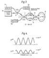
- FIG. 3 The experimental arrangement used to examine the performance of the embodiment of the present invention shown in Figure 1 is illustrated in Figure 3, in which the entire device is made from standard single mode telecommunications-type optical fibre with fused-tapered couplers. Those elements in common with the Figure 1 embodiment are referenced by the same numerals.
- the technique adopted to scan the relative phase difference, ⁇ was to launch light of a constant wavelength into port 1 and to vary periodically the length of the fibre in arm 22 with the piezo-electric stretcher 27.
- stretching the device applied a constant phase shift linearly related to an applied voltage ramp, which was in turn synchronised to the timebase of an oscilloscope (not shown). Time therefore becomes directly proportional to the phase difference, ⁇ .
- An InGaAsP external cavity semiconductor diode laser 30 which had a measured operating wavelength of 1.53374 ⁇ m was used to provide the input signal.
- An optical isolator (not shown) prevented laser instabilities due to reflected signals,
- a third directional coupler 32 was spliced to the input port 1.
- the launched, transmitted and reflected signals were monitored by positioning detectors D1-D3 at three locations connected to a high resolution oscilloscope (not shown). Values of the lengths l1, l2 and l3 of the arms 22 and 24 and the loop 26 was 0.85m, 0.95m and 1.10m respectively.
- the coupler 32 had a splitting ratio of 0.55.
- the reflected peak intensities are lower in magnitude as they had to pass through the input coupler twice before detection.
- the measured values compared well with the expected values of 0.55 I in and 0.248 I in for the transmitted and reflected signals, respectively.
- the unmodulated throughput was measured to be no more than 0.026 I in , indicating that despite the fact that couplers 3 and 12 were not exactly 50:50, a good depth of modulation could be achieved. As discussed above this is consistent with the expectation that the response should be reasonably insensitive to non-optical coupling ratios and the presence of small excess losses.
- the frequency of oscillation can be as great as the modulation of the phase in one arm. This is a significant advantage over a single optical fibre loop Sagnac reflector in which reflection modulation takes place by differential phase delays in the same (loop) path or in which the coupling ratio of the splitter is modulated to vary the reflected signal.
- an optical fibre laser comprises known erbium doped silica optical fibre 34 which forms the active lasing material of a lasing cavity defined by a wavelength selective dichroic mirror 36 at one end of the fibre and a interferometer according to the present invention spliced to the other by fusion splice 38. It is pumped by the laser pump 40 in a known manner.
- a controller 42 is used to control the piezo-electro stretcher 27 which can thereby be set to vary the reflectivity of the interferometer (as regards an optical signal entering at port 1 from the fibre 34).
- the present invention is of course applicable to other laser arrangements including bulk optical lasers. It is known that the optimum output power of a laser depends on the reflectivity of its cavity mirrors.
- the present invention can be used as a variable reflectivity mirror to optimise the efficiency of the laser.
- the speed of change of the reflectivity also allows it to be used as a reflective modulator for Q-switching a laser.
- the reflected and transmitted portions of the input optical signal vary periodically with frequency.
- the present application can therefore be used as a frequency filter, for example to select portions from a comb of frequencies.
Landscapes
- Physics & Mathematics (AREA)
- General Physics & Mathematics (AREA)
- Nonlinear Science (AREA)
- Spectroscopy & Molecular Physics (AREA)
- Optics & Photonics (AREA)
- Instruments For Measurement Of Length By Optical Means (AREA)
- Investigating Or Analysing Materials By Optical Means (AREA)
Abstract
An an all optical fibre interferometer is formed from an optical fibre Mach-Zehnder interferometer (25) whose output ports (18,20) are coupled by an optical fibre loop (20) which relaunches any optical signal output from either of the output ports (18,20) into a respective one of the output ports (20,18). A piezo-electric stretcher 26 is used to adjust the length of the arm (22) relative to the other arm (24) in response to a measurand. The interferometer outputs at port 1 an intereference signal dependant on the relative optical path length ofthe arms (22,24) allowing a measurand to be monitored via the same port 1 as the input optical signal Iin is coupled. This allows remote sensing via a single optical fibre coupled to port 1. The interferometer also finds application as a reflection modulator as a variable reflectivity mirror and Q-switch for a fibre laser.
Description
- This invention relates to interferometers.
- One well known interferometer is the Mach-Zehnder interferometer in which an optical splitter splits an optical singal into two portions which propagate along distinct optical paths to an optical combiner. The relative phase difference between the two portions at the combiner can be monitored by allowing them to interfere and measuring the intensity of the resultant optical signal. The relative phase difference depends on the difference between the two optical path lengths. Such an interferometer can be used as a sensor or as a modulator by including means for altering the difference in optical path length between the two arms in response to a change in a measurand or modulating signal. An example is disclosed in a review article entitled "Optical Fibre Sensor Technology," IEE Transactions on Microwave Theory and Techniques Vol MTT-30 No.4 April 1982 pp473 - 480 by Giallorenzi et al.
- A disadvantage of known Mach-Zehnder interferometers when used as sensors is that the interfering portions have to be monitored at an output port which is seperated from the input port. If it is necessary to monitor the condition of interferometer from a distance an optical waveguide, for example an optical fibre, needs to be coupled to the output to allow propagation of the optical portions back to the monitor. This can involve large amounts of fibre if the sensor is positioned remotely.
- In this specification the term "optical" is intended to refer to that part of the electromagnetic spectrum which is generally known as the visible region together with those parts of the infra-red and ultraviolet regions at each end of the visible region which are capable for example of being transmitted by dielectric optical waveguides such as optical fibres.
- According to the present invention an interferometer comprises an optical splitter having at least one input port and two optical splitter output ports; an optical combiner having two optical combiner input ports and two outputs ports; a first and a second optical arm each optically coupling a respective one of optical splitter output ports with one of the optical combiner input ports; and an adjustment means for changing the optical path length of one arm relative to the other; characterised in including relaunching means for relaunching any optical signal output from either of the combiner output ports into a respective one of the combiner output ports.
- The signals exiting the combiner output ports which are produced as a result of an input signal being launched into an input port of the optical splitter (as in known Mach-Zehnder interferometers) will be relaunched into the optical combiner output ports and will thereby undergo a second transit through the Mach-Zehnder portion of the interferometer.
- The optical splitter now acts as an optical combiner for the optical signals that have propagated back along the interferometer arms. These signals interfere. As will be explained in more detail later the resultant interference signal changes with the relative optical path length of the two arms but in this case the interference signal leaves the interferometer from the input port into which the original input optical signal was coupled can be monitored.
- The reflected signal can therefore propagate back to the monitor station along the same optical waveguide which supplies the optical signal to the optical splitter. That part of the signal emerging from the input port into which the input signal was launched is by convention termed the reflected signal, and that emerging from the other input port if there is one (for example when the splitter is a four port fused fibre coupler) is termed the transmitted signal.
- The Mach-Zehnder portion of the interferometer may be formed from bulk optic components comprising a first and a second beam splitter, and a first and a second mirror in known manner. Light entering the device is split into a first and a second portion by the first beam splitter. The portions each follow a separate optical path to the optical combiner, for example one defined by the first and second mirror respectively, the other being a straight optical path, where they recombine to produce first and second output interference signals at a first and second output port.
- The relaunching means of the present invention used with such a bulk optic Mach-Zehnder interferometer may comprise two mirrors positioned such that the output signal from the first output port of the Mach-Zehnder interferometer is incident on a third mirror, and then on a fourth mirror and finally is relaunched into the Mach-Zehnder interferometer via the second input port. An output signal from the second input port will be incident on first the second mirror and then onthe first mirror to be relaunched into the Mach-Zehnder interferometer via the first input port. Alternatively the third and fourth mirrors may be arranged to relaunch light from each output back into the same output.
- A particularly convenient form of the interferometer is formed by a pair of 4-port optical couplers optically coupled by a pair of optical waveguides, for example optical fibres, whcih constitute the optical arms, the means for relaunching comprising a looped optical waveguide formed between the first and second output ports of the Mach-Zehnder interferometer. Such a device may be formed from a single length of fibre, is robust and does not suffer from any of the alignment problems which would be incurred if the device were made either entirely, or partially from bulk optics.
- The present invention may also be formed from planar waveguides, for example formed in a LiNbO₃ substrate. In such an embodiment the optical splitter may have a single input.
- The device is employable as a sensor by arranging for the adjustment means to be sensitive to the quantity to be measured, for example by mechanical stretching due to incident vibrations or by an electro-optical effect.
- It will be appreciated that the invention is applicable to Mach-Zehnder interferometers in general and is not limited to specific types of splitters, combiners or relaunching means nor specific adjustment means for changing the optical path length of one arm relative to the other that may be mentioned by way of specific example.
- The present invention can find applications other than as a sensor by using of the property that the reflected signal can be modulated by the adjustment means. For example, the interferometer can be used as a variable output reflector for, or to provide Q-switched operation of a fibre laser.
- Embodiments of the invention will now be described by way of example only with reference to the following diagrams in which:
- Figure 1 is a schematic representation of an optical fibre interferometer according to the present invention;
- Figure 2 is a schematic representation of a bulk optical interferometer according to the present invention;
- Figure 3 is a schematic representation of an experimental arrangement used to characterise the embodiment of Figure 1;
- Figure 4 is a graph of transmitted and reflected output intensity of the embodiment of Figure 3; and
- Figure 5 is a schematic representation of a fibre laser having an interferometer according to the present invention as one of the laser mirrors.
- Referring to Figure 1 an optical fibre interferometer comprises an
optical splitter 3 havinginput ports splitter output ports optical combiner 12 having opticalcombiner input ports output ports ports arms interferometer 25, andports loop 26 constituting the relaunching means. The device was formed from a single, single-mode optical fibre, thesplitter 3 and combiner 12 being fused tapered couplers made in known manner. Other couplers may be employed, for example polished optical couplers or optical waveguide couplers if the invention is implemented for example in a LiNbO₃ substrate. - A piezo-
electric stretcher 27 can be actuated to change the optical path length of onearm 22 relative to the other 24. Other devices capable of so changing the relative optical path length of thearms - Referring to Figure 2, the bulk optics equivalent to figure 1 is shown, equivalent features being indicated by the same numerals primed. An optical splitter and combiner 3′, 12′ are formed by half mirror beam splitters, the
arms 22′ and 24′ being defined byfull mirrors 22′A and 24′A and loop 26′ byfull mirrors 26′A and 28′B. The optical path length is adjustable by means of themovable prism 28′. - A methodology for setting up equations to describe optical fibre interferometers of arbitrary complexity, which involve directional couplers, has been described in an article by P.Urquhart, Applied Optics Vol 26 (1987) 456. Using this approach, a set of linear equations can be set up which establishes the relationships between the components of the complex electric field propagating in both directions at the points of the device which are immediately adjacent to the couplers. There are as many equations as there are unknown quantities, which in the present case is sixteen. This formalism gives the same results as the method which relies on summation of field components which describe the various pathways through the structure but is more suitable for use with complicated structures. In analysing the interferometer of the present invention it is assumed that the state of polarisation remains constant throughout the device. In practice it was found that polarisation control was necessary. This can be achieved by any one of the following: (a) appropriate adjustment of the lie of the optical fibre, (b) using polarisation controllers, c) using polarising maintaining fibres and polarisation couplers.
- It is assumed Ki and γi are the intensity coupling ratio and the coupling loss respectively, of the
splitter 2 and combiner 12, where i = 1 or 2 for the fibre couplers constituting the splitter and combiner respectively. The lengths of thearms loop 20 are l₁, l₂ and l₃. The (field) loss and propagation constant are α and β, respectively. β is given by
β = 2πne/λ (1)
where ne is the effective fibre refractive index and λ is the free space wavelength. - When solved simultaneously the initial equations give solutions for the outputs at
ports
I

where δ is the phase difference between the two arms of lengths l₁ and l₂, and is given by
δ = β(l₁ - l₂). (3) - The constants are given by Ai, Bi and Ci in which i = 1, 2 depending upon whether the output is from
port
A₁ = r₁t₁ exp (-α(l₁ + l₂)) (4)
B₁ = r₂ (l-K₁) (l-γ₁) exp(-2αl₁) (5)
C₁ = -(r₂K₁) (l-γ₁) exp(-2αl₂) (6)
A₂ = t₁t₂exp(-α(l₁+ l₂)), (7)
B₂ = - r₁r₂exp(-2αl₁)/2 (8)
C₂ = r₁r₂exp(-2α1₂)/2 (9) - The amplitude transmissivity and reflectivity terms that would apply to a loop reflector made from zero loss fibre with coupling ratio Ki and coupling loss γi have been identified in the analysis and are given by ri and ti, respectively. These terms are given by the following equations:
ri = 2K
ti = (1-2Ki) (1-γi). (11) - When the optical path lengths of the arms l₁ and l₂ are equal, δ is zero and equation (2) becomes
II

Equation (12) is an invariant function with respect to δ; that is light is merely split unequally between the two ports. The device is then showing loop reflector characteristics. - Consider now that both couplers have coupling ratios of 1/2. The output then takes on the following simple form.
II

- It is noteworthy that ti has a small value even when K is approximately, but not exactly, equal to 1/2. It can thus be seen from equations (4) and (7) that A₁ and A₂ are approximately zero. Consequently, we would expect that equation (13) would apply to a good approximation even when the couplers do not have a splitting ratio of exactly 50:50. Such insensitivity to an important component value is to be seen as a desirable feature of the present invention. A further feature of equation (13) is that we can easily see the effect of losses in
arms loop 20, which could arise from making the device from splicing two couplers together in three positions. The length-loss products αli, which appear in equations (4) to (9) and (13) can be multiplied by an appropriate scaling factor. The discrete splice loss is thus replaced by an equivalent distributed loss in the arm of length li. As can be seen from the constants Bi and Ci in equation (13), the effect of splice losses is to bring about a small reduction in both the peak output intensity and the depth of modulation. - In the situation where the losses of the fibre and both couplers take on the low values of fractions of a dB, which are routinely achievable in practice the intensity equations can be written to a good approximation in the following form:
II

Equation (14) shows that, as required by conservation of energy, the sum of the outputs from the two ports is unity. It can also be seen from equation (14) that when low loss components are used in conjunction with 50:50 couplers, the light output from the two ports is determined only by the relative phase change, δ associated with the transits in the two arms. δ depends upon the difference in the optical path length of the twoarms - The experimental arrangement used to examine the performance of the embodiment of the present invention shown in Figure 1 is illustrated in Figure 3, in which the entire device is made from standard single mode telecommunications-type optical fibre with fused-tapered couplers. Those elements in common with the Figure 1 embodiment are referenced by the same numerals. The technique adopted to scan the relative phase difference, δ, was to launch light of a constant wavelength into
port 1 and to vary periodically the length of the fibre inarm 22 with the piezo-electric stretcher 27. Thus stretching the device applied a constant phase shift linearly related to an applied voltage ramp, which was in turn synchronised to the timebase of an oscilloscope (not shown). Time therefore becomes directly proportional to the phase difference, δ. - An InGaAsP external cavity
semiconductor diode laser 30 which had a measured operating wavelength of 1.53374µm was used to provide the input signal. An optical isolator (not shown) prevented laser instabilities due to reflected signals, A thirddirectional coupler 32 was spliced to theinput port 1. The launched, transmitted and reflected signals were monitored by positioning detectors D1-D3 at three locations connected to a high resolution oscilloscope (not shown). Values of the lengths l₁, l₂ and l₃ of thearms loop 26 was 0.85m, 0.95m and 1.10m respectively. The fused couplers were designed to be 50:50 at 1550 nm. Their measured coupling ratios at the operating wavelength were K₁≃K₂=0.52±0.01. Both couplers had excess losses of about 0.05 to 0.1 dB. Thecoupler 32 had a splitting ratio of 0.55. - The experimentally measured transmitted and reflected output intensities from
ports couplers - From the calculated variation of output power with respect to phase it has shown that a variety of output responses is possible. Two responses are of particular interest. When the two constituent arms are of equal optical length the device acts as frequency independent reflector. When both of the direction couplers have a coupling ratio of 50% the dependence of output power from the two ports on the relative phase difference, δ, of the signals in the two arms are given simply by sin²(δ) and cos²(δ). A relative phase variation can be brought about by a variety of means which means are well known in the art of Mach-Zehnder sensor technology, and modulation is thus possible over the full range of power levels. The experiment confirmed that by elongating one of the arms by a few microns the sin²(δ) and cos²(δ) response predicted by the calculations. An important strength of the present invention is that nearly full modulation is obtained even when non-optimal 50% couplers are used.
- Because the reflection modulation depends on a relative phase difference between the two arms of the interferometer, the frequency of oscillation can be as great as the modulation of the phase in one arm. This is a significant advantage over a single optical fibre loop Sagnac reflector in which reflection modulation takes place by differential phase delays in the same (loop) path or in which the coupling ratio of the splitter is modulated to vary the reflected signal.
- Referring now to figure 5, an optical fibre laser comprises known erbium doped silica
optical fibre 34 which forms the active lasing material of a lasing cavity defined by a wavelength selectivedichroic mirror 36 at one end of the fibre and a interferometer according to the present invention spliced to the other byfusion splice 38. It is pumped by thelaser pump 40 in a known manner. Acontroller 42 is used to control the piezo-electro stretcher 27 which can thereby be set to vary the reflectivity of the interferometer (as regards an optical signal entering atport 1 from the fibre 34). The present invention is of course applicable to other laser arrangements including bulk optical lasers. It is known that the optimum output power of a laser depends on the reflectivity of its cavity mirrors. The present invention can be used as a variable reflectivity mirror to optimise the efficiency of the laser. The speed of change of the reflectivity also allows it to be used as a reflective modulator for Q-switching a laser. - The reflected and transmitted portions of the input optical signal vary periodically with frequency. The present application can therefore be used as a frequency filter, for example to select portions from a comb of frequencies.
Claims (7)
1. An interferometer comprising -
an optical splitter having at least one input port and two optical splitter output ports;
an optical combiner having two optical combiner input ports and two output ports;
a first and a second optical arm each optically coupling a respective one of optical splitter output ports with one of the optical combiner input ports; and
an adjustment means for changing the optical path length of one arm relative to the other;
characterised in including relaunching means for relaunching any optical signal output from either of the output ports into a respective one of the output ports.
2. An interferometer as claimed in claim 1 in which the optical splitter and optical combiner are optical waveguide couplers and the arms are optical waveguides.
3. An interferometer as claimed in claim 2 in which the relaunching means comprises an optical waveguide optically coupling the two optical combiner outputs.
4. An interferometer as claimed in claim 2 in which all the optical waveguides comprise optical fibres.
5. An interferometer as claimed in claim 4 in which all the waveguides are formed from a single optical fibre.
6. A laser having at least one end of lasing cavity defined by an intrerferometer as claimed in any preceding claim.
7. A laser as claimed in claim 6 in which the lasing cavity comprises an optical fibre lasing medium and the interferometer is an all fibre optical interferometer.
Applications Claiming Priority (2)
| Application Number | Priority Date | Filing Date | Title |
|---|---|---|---|
| GB8825481 | 1988-11-01 | ||
| GB888825481A GB8825481D0 (en) | 1988-11-01 | 1988-11-01 | Interferrometer |
Publications (1)
| Publication Number | Publication Date |
|---|---|
| EP0376449A1 true EP0376449A1 (en) | 1990-07-04 |
Family
ID=10646077
Family Applications (1)
| Application Number | Title | Priority Date | Filing Date |
|---|---|---|---|
| EP89311299A Withdrawn EP0376449A1 (en) | 1988-11-01 | 1989-11-01 | Interferometer |
Country Status (8)
| Country | Link |
|---|---|
| EP (1) | EP0376449A1 (en) |
| JP (1) | JPH04501608A (en) |
| KR (1) | KR900702329A (en) |
| AU (1) | AU617556B2 (en) |
| CA (1) | CA2001914A1 (en) |
| DK (1) | DK80391A (en) |
| GB (1) | GB8825481D0 (en) |
| WO (1) | WO1990005282A1 (en) |
Cited By (29)
| Publication number | Priority date | Publication date | Assignee | Title |
|---|---|---|---|---|
| WO1996016350A1 (en) * | 1994-11-21 | 1996-05-30 | Akzo Nobel N.V. | Sagnac interferometer and reflective modulator comprising same |
| EP0779689A3 (en) * | 1995-12-16 | 1998-04-01 | Nortel Networks Corporation | Gain clamped optical amplifier |
| WO1999010761A2 (en) * | 1997-08-22 | 1999-03-04 | HEINRICH-HERTZ-INSTITUT FüR NACHRICHTENTECHNIK BERLIN GMBH | Quasi rectangular wave filter |
| EP1084590A1 (en) * | 1998-04-03 | 2001-03-21 | The Board Of Trustees Of The Leland Stanford Junior University | Folded sagnac sensor array |
| WO2001038925A1 (en) * | 1999-11-23 | 2001-05-31 | Nanovation Technologies, Inc. | Waveguide optical phase shifter |
| WO2001038924A1 (en) * | 1999-11-23 | 2001-05-31 | Nanovation Technologies, Inc. | Optical mach-zehnder switch having a movable phase shifter |
| WO2001038922A2 (en) * | 1999-11-23 | 2001-05-31 | Nanovation Technologies, Inc. | Analog optical switch using an integrated mach-zehnder interferometer having a movable phase shifter |
| WO2001038923A1 (en) * | 1999-11-23 | 2001-05-31 | Nanovation Technologies, Inc. | Optical mach-zehnder switch with movable phase shifter |
| WO2001086333A2 (en) * | 2000-05-06 | 2001-11-15 | Profile Optische Systeme Gmbh | Emulator for second order polarization mode dispersion (pmd) |
| US6912088B2 (en) | 2000-07-12 | 2005-06-28 | Thorlabs Gmbh | Polarization mode dispersion emulator |
| WO2006064258A1 (en) * | 2004-12-17 | 2006-06-22 | British Telecommunications Public Limited Company | Optical system |
| US7667849B2 (en) | 2003-09-30 | 2010-02-23 | British Telecommunications Public Limited Company | Optical sensor with interferometer for sensing external physical disturbance of optical communications link |
| US7697795B2 (en) | 2005-03-04 | 2010-04-13 | British Telecommunications Public Limited Company | Acoustic modulation |
| US7755971B2 (en) | 2005-03-04 | 2010-07-13 | British Telecommunications Public Limited Company | Sensing system |
| US7796896B2 (en) | 2003-09-30 | 2010-09-14 | British Telecommunications Plc | Secure optical communication |
| US7817279B2 (en) | 2006-02-24 | 2010-10-19 | British Telecommunications Public Limited Company | Sensing a disturbance |
| US7848645B2 (en) | 2004-09-30 | 2010-12-07 | British Telecommunications Public Limited Company | Identifying or locating waveguides |
| US7961331B2 (en) | 2006-02-24 | 2011-06-14 | British Telecommunications Public Limited Company | Sensing a disturbance along an optical path |
| US7974182B2 (en) | 2004-03-31 | 2011-07-05 | British Telecommunications Public Limited Company | Evaluating the position of a disturbance |
| US7995197B2 (en) | 2004-09-30 | 2011-08-09 | British Telecommunications Public Limited Company | Distributed backscattering |
| US8000609B2 (en) | 2005-04-14 | 2011-08-16 | British Telecommunications Public Limited Company | Communicating or reproducing an audible sound |
| US8003932B2 (en) | 2005-06-02 | 2011-08-23 | British Telecommunications Public Limited Company | Evaluating the position of a disturbance |
| US8027584B2 (en) | 2006-02-24 | 2011-09-27 | British Telecommunications Public Limited Company | Sensing a disturbance |
| US8045174B2 (en) | 2004-12-17 | 2011-10-25 | British Telecommunications Public Limited Company | Assessing a network |
| JP2011232347A (en) * | 2000-03-06 | 2011-11-17 | Board Of Trustees Of The Leland Stanford Junior Univ | Acoustic sensor, method and sensor for detecting acoustic signal |
| US8077779B2 (en) | 2002-07-24 | 2011-12-13 | Apple Inc. | Method and apparatus for variable accuracy inter-picture timing specification for digital video encoding with reduced requirements for division operations |
| CN101625258B (en) * | 2009-08-05 | 2012-03-21 | 上海华魏光纤传感技术有限公司 | Optical fiber vibration sensing system based on Mach-Zehnder interferometer and sensing method |
| US8396360B2 (en) | 2005-03-31 | 2013-03-12 | British Telecommunications Public Limited Company | Communicating information |
| US8670662B2 (en) | 2006-04-03 | 2014-03-11 | British Telecommunications Public Limited Company | Evaluating the position of an optical fiber disturbance |
Families Citing this family (3)
| Publication number | Priority date | Publication date | Assignee | Title |
|---|---|---|---|---|
| US5615037A (en) * | 1995-01-17 | 1997-03-25 | Massachusetts Institute Of Technology | Sub-octave bandpass optical remote antenna link modulator and method therefor |
| CA2311966A1 (en) * | 1999-06-23 | 2000-12-23 | Stavros Dariotis | Optical fiber mach-zehnder interferometer employing miniature bends |
| DE19935908C1 (en) * | 1999-07-30 | 2000-09-07 | Siemens Ag | Bragg grating sensor for detecting physical quantity |
Citations (5)
| Publication number | Priority date | Publication date | Assignee | Title |
|---|---|---|---|---|
| US3589794A (en) * | 1968-08-07 | 1971-06-29 | Bell Telephone Labor Inc | Optical circuits |
| DE3014719A1 (en) * | 1980-04-17 | 1981-10-22 | Licentia Patent-Verwaltungs-Gmbh, 6000 Frankfurt | Optical switching device responsive to polarisation state - uses direction couplers and polarisation and/or phase setting elements for gating light waves |
| EP0247882A1 (en) * | 1986-05-30 | 1987-12-02 | BRITISH TELECOMMUNICATIONS public limited company | Optical resonating device |
| US4725141A (en) * | 1984-08-22 | 1988-02-16 | The General Electric Company, P.L.C. | Interferometers |
| US4753529A (en) * | 1986-06-23 | 1988-06-28 | Litton Systems, Inc. | Apparatus and method for precision adjustment of interferometer pathlength difference |
Family Cites Families (1)
| Publication number | Priority date | Publication date | Assignee | Title |
|---|---|---|---|---|
| GB8829546D0 (en) * | 1988-12-19 | 1989-02-08 | British Telecomm | Non-linear interferometer |
-
1988
- 1988-11-01 GB GB888825481A patent/GB8825481D0/en active Pending
-
1989
- 1989-10-31 CA CA002001914A patent/CA2001914A1/en not_active Abandoned
- 1989-11-01 KR KR1019900701375A patent/KR900702329A/en not_active Application Discontinuation
- 1989-11-01 AU AU45139/89A patent/AU617556B2/en not_active Ceased
- 1989-11-01 EP EP89311299A patent/EP0376449A1/en not_active Withdrawn
- 1989-11-01 WO PCT/GB1989/001304 patent/WO1990005282A1/en unknown
- 1989-11-01 JP JP1511689A patent/JPH04501608A/en active Pending
-
1991
- 1991-04-30 DK DK080391A patent/DK80391A/en not_active Application Discontinuation
Patent Citations (5)
| Publication number | Priority date | Publication date | Assignee | Title |
|---|---|---|---|---|
| US3589794A (en) * | 1968-08-07 | 1971-06-29 | Bell Telephone Labor Inc | Optical circuits |
| DE3014719A1 (en) * | 1980-04-17 | 1981-10-22 | Licentia Patent-Verwaltungs-Gmbh, 6000 Frankfurt | Optical switching device responsive to polarisation state - uses direction couplers and polarisation and/or phase setting elements for gating light waves |
| US4725141A (en) * | 1984-08-22 | 1988-02-16 | The General Electric Company, P.L.C. | Interferometers |
| EP0247882A1 (en) * | 1986-05-30 | 1987-12-02 | BRITISH TELECOMMUNICATIONS public limited company | Optical resonating device |
| US4753529A (en) * | 1986-06-23 | 1988-06-28 | Litton Systems, Inc. | Apparatus and method for precision adjustment of interferometer pathlength difference |
Non-Patent Citations (4)
| Title |
|---|
| APPLIED OPTICS, vol. 27, no. 15, 1st August 1988, pages 3107-3113, Optical Society of America, New York, US; T.A. BIRKS et al.: "Jones calculus analysis of single-mode fiber Sagnac reflector" * |
| APPLIED PHYSICS LETTERS, vol. 41, no. 3, August 1982, pages 231-233, American Institute of Physics, New York, US; J.E. BOWERS: "Fiber-optical sensor for surface acoustic waves" * |
| IEEE TRANSACTIONS ON MICROWAVE THEORY AND TECHNIQUES, vol. MTT-30, no. 4, April 1982, pages 472-511, New York, US; T.G. GIALLORENZI et al.: "Optical fiber sensor technology" * |
| OPTICS AND SPECTROSCOPY, vol. 58, no. 5, May 1985, pages 675-677, The Optical Society of America, Washington, US; L.V. IOGANSEN et al.: "Multimode fiber interferometers" * |
Cited By (34)
| Publication number | Priority date | Publication date | Assignee | Title |
|---|---|---|---|---|
| WO1996016350A1 (en) * | 1994-11-21 | 1996-05-30 | Akzo Nobel N.V. | Sagnac interferometer and reflective modulator comprising same |
| EP0779689A3 (en) * | 1995-12-16 | 1998-04-01 | Nortel Networks Corporation | Gain clamped optical amplifier |
| WO1999010761A2 (en) * | 1997-08-22 | 1999-03-04 | HEINRICH-HERTZ-INSTITUT FüR NACHRICHTENTECHNIK BERLIN GMBH | Quasi rectangular wave filter |
| WO1999010761A3 (en) * | 1997-08-22 | 1999-05-06 | Hertz Inst Heinrich | Quasi rectangular wave filter |
| EP1084590A1 (en) * | 1998-04-03 | 2001-03-21 | The Board Of Trustees Of The Leland Stanford Junior University | Folded sagnac sensor array |
| EP1084590B1 (en) * | 1998-04-03 | 2005-08-17 | The Board Of Trustees Of The Leland Stanford Junior University | Folded sagnac sensor array |
| WO2001038923A1 (en) * | 1999-11-23 | 2001-05-31 | Nanovation Technologies, Inc. | Optical mach-zehnder switch with movable phase shifter |
| WO2001038922A2 (en) * | 1999-11-23 | 2001-05-31 | Nanovation Technologies, Inc. | Analog optical switch using an integrated mach-zehnder interferometer having a movable phase shifter |
| WO2001038924A1 (en) * | 1999-11-23 | 2001-05-31 | Nanovation Technologies, Inc. | Optical mach-zehnder switch having a movable phase shifter |
| WO2001038922A3 (en) * | 1999-11-23 | 2002-09-12 | Nanovation Tech Inc | Analog optical switch using an integrated mach-zehnder interferometer having a movable phase shifter |
| WO2001038925A1 (en) * | 1999-11-23 | 2001-05-31 | Nanovation Technologies, Inc. | Waveguide optical phase shifter |
| JP2011232347A (en) * | 2000-03-06 | 2011-11-17 | Board Of Trustees Of The Leland Stanford Junior Univ | Acoustic sensor, method and sensor for detecting acoustic signal |
| WO2001086333A2 (en) * | 2000-05-06 | 2001-11-15 | Profile Optische Systeme Gmbh | Emulator for second order polarization mode dispersion (pmd) |
| WO2001086333A3 (en) * | 2000-05-06 | 2002-04-18 | Profile Optische Systeme Gmbh | Emulator for second order polarization mode dispersion (pmd) |
| US6912088B2 (en) | 2000-07-12 | 2005-06-28 | Thorlabs Gmbh | Polarization mode dispersion emulator |
| US8077779B2 (en) | 2002-07-24 | 2011-12-13 | Apple Inc. | Method and apparatus for variable accuracy inter-picture timing specification for digital video encoding with reduced requirements for division operations |
| US7667849B2 (en) | 2003-09-30 | 2010-02-23 | British Telecommunications Public Limited Company | Optical sensor with interferometer for sensing external physical disturbance of optical communications link |
| US7796896B2 (en) | 2003-09-30 | 2010-09-14 | British Telecommunications Plc | Secure optical communication |
| US7974182B2 (en) | 2004-03-31 | 2011-07-05 | British Telecommunications Public Limited Company | Evaluating the position of a disturbance |
| US7848645B2 (en) | 2004-09-30 | 2010-12-07 | British Telecommunications Public Limited Company | Identifying or locating waveguides |
| US7995197B2 (en) | 2004-09-30 | 2011-08-09 | British Telecommunications Public Limited Company | Distributed backscattering |
| US7656535B2 (en) | 2004-12-17 | 2010-02-02 | British Telecommunications Public Limited Company | Optical system and method for inferring a disturbance |
| US8045174B2 (en) | 2004-12-17 | 2011-10-25 | British Telecommunications Public Limited Company | Assessing a network |
| WO2006064258A1 (en) * | 2004-12-17 | 2006-06-22 | British Telecommunications Public Limited Company | Optical system |
| US7755971B2 (en) | 2005-03-04 | 2010-07-13 | British Telecommunications Public Limited Company | Sensing system |
| US7697795B2 (en) | 2005-03-04 | 2010-04-13 | British Telecommunications Public Limited Company | Acoustic modulation |
| US8396360B2 (en) | 2005-03-31 | 2013-03-12 | British Telecommunications Public Limited Company | Communicating information |
| US8000609B2 (en) | 2005-04-14 | 2011-08-16 | British Telecommunications Public Limited Company | Communicating or reproducing an audible sound |
| US8003932B2 (en) | 2005-06-02 | 2011-08-23 | British Telecommunications Public Limited Company | Evaluating the position of a disturbance |
| US7961331B2 (en) | 2006-02-24 | 2011-06-14 | British Telecommunications Public Limited Company | Sensing a disturbance along an optical path |
| US7817279B2 (en) | 2006-02-24 | 2010-10-19 | British Telecommunications Public Limited Company | Sensing a disturbance |
| US8027584B2 (en) | 2006-02-24 | 2011-09-27 | British Telecommunications Public Limited Company | Sensing a disturbance |
| US8670662B2 (en) | 2006-04-03 | 2014-03-11 | British Telecommunications Public Limited Company | Evaluating the position of an optical fiber disturbance |
| CN101625258B (en) * | 2009-08-05 | 2012-03-21 | 上海华魏光纤传感技术有限公司 | Optical fiber vibration sensing system based on Mach-Zehnder interferometer and sensing method |
Also Published As
| Publication number | Publication date |
|---|---|
| WO1990005282A1 (en) | 1990-05-17 |
| AU617556B2 (en) | 1991-11-28 |
| GB8825481D0 (en) | 1988-12-07 |
| AU4513989A (en) | 1990-05-28 |
| DK80391D0 (en) | 1991-04-30 |
| JPH04501608A (en) | 1992-03-19 |
| KR900702329A (en) | 1990-12-06 |
| DK80391A (en) | 1991-04-30 |
| CA2001914A1 (en) | 1990-05-01 |
Similar Documents
| Publication | Publication Date | Title |
|---|---|---|
| EP0376449A1 (en) | Interferometer | |
| US4962987A (en) | Optical device producing an intensity dependent phase shift | |
| US5946429A (en) | Time-division multiplexing of polarization-insensitive fiber optic michelson interferometric sensor | |
| JPS59171819A (en) | Optical fiber hydrophone | |
| US4801189A (en) | Birefringent fiber narrowband polarization coupler and method of coupling using same | |
| US5383207A (en) | Optical carrier generation using stimulated brillouin scattering | |
| US5208455A (en) | Square optical pulse generator | |
| JPS6180109A (en) | Optical multiplexer and demultiplexer | |
| Hatta et al. | Ratiometric wavelength monitor based on singlemode‐multimode‐singlemode fiber structure | |
| Laliew et al. | A linearized optical directional-coupler modulator at 1.3 m | |
| Millar et al. | Fibre reflection mach-zehnder interferometer | |
| US6246811B1 (en) | Irreversible optical device utilizing optical frequency shift | |
| Jeon et al. | Optical fiber chromatic dispersion measurement using bidirectional modulation of an optical intensity modulator | |
| US5311279A (en) | Integrated optical apparatus for the interferometric measurement of light waves | |
| US5333220A (en) | Quantum non-demolition optical tapping | |
| JPH0447214A (en) | Optical fiber gyroscope | |
| JP2002181861A (en) | Electric field sensor unit | |
| Syms | Resonant cavity sensor for integrated optics | |
| JP2003322589A (en) | Method and instrument for measuring brillouin spectrum distribution | |
| US20050169599A1 (en) | Multi-layered structure characterisation | |
| Bristow et al. | Integrated Optical Circuit Engineering For Optical Fiber Gyrocopes | |
| JPH11174268A (en) | Optical functional element | |
| Ahmed | Optical Fiber Sensors | |
| Takahashi et al. | 2× 2 optical switch and its applications | |
| D'Orazio et al. | Design and demonstration of interferometric integrated-optic sensors in Ti: LiNbO3 waveguides |
Legal Events
| Date | Code | Title | Description |
|---|---|---|---|
| PUAI | Public reference made under article 153(3) epc to a published international application that has entered the european phase |
Free format text: ORIGINAL CODE: 0009012 |
|
| AK | Designated contracting states |
Kind code of ref document: A1 Designated state(s): AT BE CH DE ES FR GB GR IT LI LU NL SE |
|
| 17P | Request for examination filed |
Effective date: 19910102 |
|
| 17Q | First examination report despatched |
Effective date: 19911004 |
|
| STAA | Information on the status of an ep patent application or granted ep patent |
Free format text: STATUS: THE APPLICATION IS DEEMED TO BE WITHDRAWN |
|
| 18D | Application deemed to be withdrawn |
Effective date: 19921013 |