EP0376214A1 - Motor control circuit - Google Patents
Motor control circuit Download PDFInfo
- Publication number
- EP0376214A1 EP0376214A1 EP89123822A EP89123822A EP0376214A1 EP 0376214 A1 EP0376214 A1 EP 0376214A1 EP 89123822 A EP89123822 A EP 89123822A EP 89123822 A EP89123822 A EP 89123822A EP 0376214 A1 EP0376214 A1 EP 0376214A1
- Authority
- EP
- European Patent Office
- Prior art keywords
- motor
- electric
- electric motor
- current
- control
- Prior art date
- Legal status (The legal status is an assumption and is not a legal conclusion. Google has not performed a legal analysis and makes no representation as to the accuracy of the status listed.)
- Withdrawn
Links
Images

Classifications
-
- H—ELECTRICITY
- H02—GENERATION; CONVERSION OR DISTRIBUTION OF ELECTRIC POWER
- H02P—CONTROL OR REGULATION OF ELECTRIC MOTORS, ELECTRIC GENERATORS OR DYNAMO-ELECTRIC CONVERTERS; CONTROLLING TRANSFORMERS, REACTORS OR CHOKE COILS
- H02P7/00—Arrangements for regulating or controlling the speed or torque of electric DC motors
- H02P7/06—Arrangements for regulating or controlling the speed or torque of electric DC motors for regulating or controlling an individual dc dynamo-electric motor by varying field or armature current
- H02P7/18—Arrangements for regulating or controlling the speed or torque of electric DC motors for regulating or controlling an individual dc dynamo-electric motor by varying field or armature current by master control with auxiliary power
- H02P7/24—Arrangements for regulating or controlling the speed or torque of electric DC motors for regulating or controlling an individual dc dynamo-electric motor by varying field or armature current by master control with auxiliary power using discharge tubes or semiconductor devices
- H02P7/28—Arrangements for regulating or controlling the speed or torque of electric DC motors for regulating or controlling an individual dc dynamo-electric motor by varying field or armature current by master control with auxiliary power using discharge tubes or semiconductor devices using semiconductor devices
- H02P7/285—Arrangements for regulating or controlling the speed or torque of electric DC motors for regulating or controlling an individual dc dynamo-electric motor by varying field or armature current by master control with auxiliary power using discharge tubes or semiconductor devices using semiconductor devices controlling armature supply only
- H02P7/29—Arrangements for regulating or controlling the speed or torque of electric DC motors for regulating or controlling an individual dc dynamo-electric motor by varying field or armature current by master control with auxiliary power using discharge tubes or semiconductor devices using semiconductor devices controlling armature supply only using pulse modulation
- H02P7/2913—Arrangements for regulating or controlling the speed or torque of electric DC motors for regulating or controlling an individual dc dynamo-electric motor by varying field or armature current by master control with auxiliary power using discharge tubes or semiconductor devices using semiconductor devices controlling armature supply only using pulse modulation whereby the speed is regulated by measuring the motor speed and comparing it with a given physical value
-
- Y—GENERAL TAGGING OF NEW TECHNOLOGICAL DEVELOPMENTS; GENERAL TAGGING OF CROSS-SECTIONAL TECHNOLOGIES SPANNING OVER SEVERAL SECTIONS OF THE IPC; TECHNICAL SUBJECTS COVERED BY FORMER USPC CROSS-REFERENCE ART COLLECTIONS [XRACs] AND DIGESTS
- Y10—TECHNICAL SUBJECTS COVERED BY FORMER USPC
- Y10S—TECHNICAL SUBJECTS COVERED BY FORMER USPC CROSS-REFERENCE ART COLLECTIONS [XRACs] AND DIGESTS
- Y10S388/00—Electricity: motor control systems
- Y10S388/935—Specific application:
- Y10S388/937—Hand tool
Definitions
- the present invention generally relates to a motor control circuit and, in particular, to a motor control circuit which is suitable for use as a switching circuit for various electric power tools such as powered screw drivers and powered drills which are powered by electric motors.
- a motor control circuit for an electric power tool included a duty ratio control circuit for controlling an output power device which is interposed in a path for supplying electric current to an electric motor to control the torque output of the motor.
- a variable resistor is included in the control circuit, and the operator can control the rotational speed and the torque output of the motor in a continually variable fashion by adjusting the variable resistor as required.
- Such a control circuit offers a high level of convenience to the user, but the need for a variable resistor and a complex control circuit means a high manufacturing cost, and ensuring necessary levels of reliability and durability presents an added difficulty.
- a primary object of the present invention is to provide a motor control circuit which is simple but offers a comparable level of convenience as a continually variable motor control circuit.
- a second object of the present invention is to provide a motor control circuit which is suitable for use as a control circuit for an electric power tool and can ensure necessary levels of reliability and durability with an extremely simple structure.
- a motor control circuit for controlling supply of electric power from a power source to an electric motor, comprising: an output power device for controlling supply of current to the motor according to a duty ratio of a control input signal supplied thereto; current detecting means for detecting an amplitude of an electric current supplied to the electric motor; and feedback means for supplying the control input signal to the output power device, the duty ratio of the input control signal being increased with an increase in the electric current supplied to the electric motor as detected by the current detecting means.
- the feedback means comprises: a triangular wave generating circuit connected to an input end of the output power device at its output end and having a first amplifier; a time constant circuit connected to its input end; and a second amplifier connected to an output end of the current detecting means at its input end, and connected to the input end of the first amplifier at its output end so as to define a positive feedback path extending from the current detecting means to the output power device and a duty ratio control path for increasing a time period of each cycle of the triangular oscillation output of the first amplifier with an increase in the electric current supplied to the electric motor as detected by the current detecting means.
- the motor control circuit is provided with two control modes for high and low torque output conditions, and the aforementioned control circuit is operated only in the low torque output conditions, so that the user can make use of the full capability of the motor when a full power is required on the one hand and the convenient control action in the reduced capability condition of the motor. Further, in this case, the two step switch over can be carried out in a smooth fashion even when such a switch over is made after the motor has run into a heavy load.
- FIG. 1 is a block diagram of the switch circuit of an electric power tool, and, in Figure 1, a motor M is connected to a power source E by way of a main circuit 10 which comprises a normal rotation control switch unit 11 and a reverse rotation control unit 12 so that power is supplied to the motor M and the motor is driven in a desired direction by turning on one of the switch units 11 and 12.
- a main circuit 10 which comprises a normal rotation control switch unit 11 and a reverse rotation control unit 12 so that power is supplied to the motor M and the motor is driven in a desired direction by turning on one of the switch units 11 and 12.
- the main current 10 further comprises an output device 14 forming a part of a low speed control circuit 13 and a shorting switch unit 15 forming a high speed control circuit which are connected in parallel with each other, and the torque output of the motor M is controlled by carrying out a switching control on the output device 14 while the shorting switch unit 15 when it is turned on directly connects the motor M to the power source E so as to drive the motor M at high speed.
- the low speed control circuit 13 consists of a triangular wave generating circuit 16, a switching circuit 17, and the aforementioned output device 14.
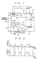
- the triangular wave generating circuit 16 is connected to either end of the aforementioned motor M via diodes D1 and D2 which are connected in normal direction, and, as shown in Figure 2, consists of a resistor R1, a capacitor C1 and a comparator 18 so as to generate a triangular wave (refer to the triangular wave of Figure 3) having alternating ON intervals and OFF intervals and, at the same time, a control signal "a" is produced during the ON intervals (signal charging intervals) as shown in Figure 3.
- a constant voltage divided by resistors R2 and R3 is applied to a non-inverting input of the comparator 18 from a node "p" and a charge/discharge voltage of a charge/discharge circuit consisting of the resistor R1 and the capacitor C1 is supplied to a inverting input of the comparator 18 from a node "q” so as to produce a control signal "a” according to its inputs.
- the output from the comparator 18 is supplied to the switching circuit 17 as a control signal "a” so as to carry out a switching control on the output device 14 by a duty ratio corresponding to the oscillation output for drive control of the motor M.
- the comparator output is also fed back to the inverting input of the comparator 18 from a node "r" via a diode D3 for charging the capacitor C1 and creating a hysteresis.
- the oscillation output is also supplied to the non-inverting input of an amplifier circuit 20 of a motor current detecting circuit 19, which is described hereinafter, from the node between the resistors R4 and R5.
- a resistor R6 forming a part of the motor current detecting circuit 19 for detecting the current supplied through the motor M.
- the motor current detecting circuit 19 consists of the aforementioned resistor R6 and the amplifier circuit 22 which amplifies the voltage developed across the resistor R6 and produces a detection signal "b" representing the increase and decrease of the current flowing through the resistor R6.
- the detection signal "b” is fed back to the triangular wave generating circuit 16 in such a manner that the control signal "a” of the triangular wave generating circuit 16 may be increased so as to increase the control current supplied to the motor M in response to the increase in the electric current supplied through the motor M.
- the amplifier circuit 20 amplifies a voltage obtained as a difference between the comparator output derived from a node "r" and a voltage derived (which is obtained by converting the motor current into a voltage) from the resistor R6, and, therefore, produces an amplified output (detection signal "b") which is synchronized with the oscillation output of the comparator 18.
- the amplified output is supplied to a pair of points in the capacitor charge/discharge circuit by way of a resistor R7 to control the charge and discharge of the capacitor C1 by variably controlling the voltage across these points. In other words, in order to control the voltage across the two point, the output of the amplifier circuit 20 is high when the motor current is small and is low when the motor current is large.
- the triangular wave generating circuit 16 When no load is applied to the motor M, the triangular wave generating circuit 16 produces a basic triangular wave, and the switching circuit 17 is activated by the control signal "a" having ON intervals of time duration T1 so as to drive the motor M via the output device 14 accordingly.
- the comparator 18 its oscillation output is fed back to its inverting input to charge the capacitor C1, and this charge voltage is supplied to the comparator 18 so that the oscillation may be maintained according to the result of a comparison between the charge voltage and a constant voltage of the node "p".
- the duration T1 of each of the ON intervals of the oscillation output is small when no load is applied to the motor M, and the switching circuit 17 therefore switches over the output device 14 according to a low pulse duty condition.
- the amplifier circuit 20 compares the voltage derived from the resistor R6 and the oscillation voltage from the comparator 18, and controls the voltage across the two points according to the increase in the voltage across the resistor R6, and increases the charge time for the capacitor C1 with the increase in the motor current to charge the oscillation time constant of the comparator 18.
- the switching circuit 17 drives the output device 14 with an increased duty ratio in response to the increase in the time duration of the ON intervals. Therefore, when the load of the motor is increased from a state of low speed rotation, the control current of the motor M is automatically increased and its torque output is increased so that a control state equivalent to a continually variable speed control can be obtained.
- the shorting switch unit 15 When a high speed condition is selected, the shorting switch unit 15 is turned on, and the motor M is directly driven by the power source E with the result that a high speed condition is produced. Since such a switch over takes place when the motor torque is high, a shock resulting from the switch over is reduced and a smooth operation is made possible.
- the switch circuit is capable of only a speed control of two steps, high and low, a rotation control equivalent to a continuously variable control can be accomplished and a high level of convenience can be achieved by using simple and economical circuit structure.
Abstract
A motor control circuit for controlling supply of electric power from a power source to an electric motor, in particular for use in electric power tools, comprising: an output power device for controlling supply of current to the motor according to a duty ratio of a control input signal supplied thereto; current detecting means for detecting an amplitude of an electric current supplied to the electric motor; and feedback means for supplying the control input signal to the output power device, the duty ratio of the input control signal being increased with an increase in the electric current supplied to the electric motor as detected by the current detecting means. Since the torque output of the motor is increased when such a need arises, the need for more a complex and expensive continually variable speed control system is eliminated.
Description
- The present invention generally relates to a motor control circuit and, in particular, to a motor control circuit which is suitable for use as a switching circuit for various electric power tools such as powered screw drivers and powered drills which are powered by electric motors.
- Conventionally, a motor control circuit for an electric power tool included a duty ratio control circuit for controlling an output power device which is interposed in a path for supplying electric current to an electric motor to control the torque output of the motor. A variable resistor is included in the control circuit, and the operator can control the rotational speed and the torque output of the motor in a continually variable fashion by adjusting the variable resistor as required.
- Such a control circuit offers a high level of convenience to the user, but the need for a variable resistor and a complex control circuit means a high manufacturing cost, and ensuring necessary levels of reliability and durability presents an added difficulty.
- To eliminate this problem, it is possible to control the output of the motor in two steps, and reduce the manufacturing cost through the use of a two-position switch mechanism instead of using a variable resistor. However, as the motor can be controlled only in two steps, a satisfactory level of convenience cannot be obtained.
- In view of such problems of the prior art, a primary object of the present invention is to provide a motor control circuit which is simple but offers a comparable level of convenience as a continually variable motor control circuit.
- A second object of the present invention is to provide a motor control circuit which is suitable for use as a control circuit for an electric power tool and can ensure necessary levels of reliability and durability with an extremely simple structure.
- According to the present invention, these and other objects can be accomplished by providing a motor control circuit for controlling supply of electric power from a power source to an electric motor, comprising: an output power device for controlling supply of current to the motor according to a duty ratio of a control input signal supplied thereto; current detecting means for detecting an amplitude of an electric current supplied to the electric motor; and feedback means for supplying the control input signal to the output power device, the duty ratio of the input control signal being increased with an increase in the electric current supplied to the electric motor as detected by the current detecting means.
- According to the present invention, since the torque output of the motor is increased as the load on the motor is increased, a control action which is equivalent to a continually variable speed control can be achieved.
- According to a preferred embodiment of the present invention, the feedback means comprises: a triangular wave generating circuit connected to an input end of the output power device at its output end and having a first amplifier; a time constant circuit connected to its input end; and a second amplifier connected to an output end of the current detecting means at its input end, and connected to the input end of the first amplifier at its output end so as to define a positive feedback path extending from the current detecting means to the output power device and a duty ratio control path for increasing a time period of each cycle of the triangular oscillation output of the first amplifier with an increase in the electric current supplied to the electric motor as detected by the current detecting means.
- In an application which is suitable for use in an electric power tool, the motor control circuit is provided with two control modes for high and low torque output conditions, and the aforementioned control circuit is operated only in the low torque output conditions, so that the user can make use of the full capability of the motor when a full power is required on the one hand and the convenient control action in the reduced capability condition of the motor. Further, in this case, the two step switch over can be carried out in a smooth fashion even when such a switch over is made after the motor has run into a heavy load.
- Now the present invention is described in the following in terms of a specific embodiment with reference to the appended drawings, in which:
- Figure 1 is a circuit diagram of a preferred embodiment of the motor control circuit for a power tool according to the present invention;
- Figure 2 is a more detailed circuit diagram of the circuit of Figure 1; and
- Figure 3 is a wave form diagram thereof.
- Now an embodiment of the present invention is described in the following with reference to the appended drawings.
- Figure 1 is a block diagram of the switch circuit of an electric power tool, and, in Figure 1, a motor M is connected to a power source E by way of a
main circuit 10 which comprises a normal rotationcontrol switch unit 11 and a reverserotation control unit 12 so that power is supplied to the motor M and the motor is driven in a desired direction by turning on one of theswitch units - The main current 10 further comprises an
output device 14 forming a part of a lowspeed control circuit 13 and ashorting switch unit 15 forming a high speed control circuit which are connected in parallel with each other, and the torque output of the motor M is controlled by carrying out a switching control on theoutput device 14 while theshorting switch unit 15 when it is turned on directly connects the motor M to the power source E so as to drive the motor M at high speed. - The low
speed control circuit 13 consists of a triangularwave generating circuit 16, aswitching circuit 17, and theaforementioned output device 14. The triangularwave generating circuit 16 is connected to either end of the aforementioned motor M via diodes D1 and D2 which are connected in normal direction, and, as shown in Figure 2, consists of a resistor R1, a capacitor C1 and acomparator 18 so as to generate a triangular wave (refer to the triangular wave of Figure 3) having alternating ON intervals and OFF intervals and, at the same time, a control signal "a" is produced during the ON intervals (signal charging intervals) as shown in Figure 3. - Referring to Figure 2, a constant voltage divided by resistors R2 and R3 is applied to a non-inverting input of the
comparator 18 from a node "p" and a charge/discharge voltage of a charge/discharge circuit consisting of the resistor R1 and the capacitor C1 is supplied to a inverting input of thecomparator 18 from a node "q" so as to produce a control signal "a" according to its inputs. In this case, the output from thecomparator 18 is supplied to theswitching circuit 17 as a control signal "a" so as to carry out a switching control on theoutput device 14 by a duty ratio corresponding to the oscillation output for drive control of the motor M. Meanwhile, the comparator output is also fed back to the inverting input of thecomparator 18 from a node "r" via a diode D3 for charging the capacitor C1 and creating a hysteresis. Likewise, the oscillation output is also supplied to the non-inverting input of anamplifier circuit 20 of a motorcurrent detecting circuit 19, which is described hereinafter, from the node between the resistors R4 and R5. - Between the
output device 14 and the power source E is interposed a resistor R6 forming a part of the motorcurrent detecting circuit 19 for detecting the current supplied through the motor M. - The motor
current detecting circuit 19 consists of the aforementioned resistor R6 and the amplifier circuit 22 which amplifies the voltage developed across the resistor R6 and produces a detection signal "b" representing the increase and decrease of the current flowing through the resistor R6. The detection signal "b" is fed back to the triangularwave generating circuit 16 in such a manner that the control signal "a" of the triangularwave generating circuit 16 may be increased so as to increase the control current supplied to the motor M in response to the increase in the electric current supplied through the motor M. - The
amplifier circuit 20 amplifies a voltage obtained as a difference between the comparator output derived from a node "r" and a voltage derived (which is obtained by converting the motor current into a voltage) from the resistor R6, and, therefore, produces an amplified output (detection signal "b") which is synchronized with the oscillation output of thecomparator 18. The amplified output is supplied to a pair of points in the capacitor charge/discharge circuit by way of a resistor R7 to control the charge and discharge of the capacitor C1 by variably controlling the voltage across these points. In other words, in order to control the voltage across the two point, the output of theamplifier circuit 20 is high when the motor current is small and is low when the motor current is large. - The operation of the above described switch circuit for a power tool is now described in the following. Normally, since the
shorting switch unit 15 is open, and the lowsped control circuit 13 is in an operable state, the motor M is driven at low speed in a desired direction by turning on either the normal rotationcontrol switch unit 11 or the reverse rotationcontrol switch unit 12. - When no load is applied to the motor M, the triangular
wave generating circuit 16 produces a basic triangular wave, and theswitching circuit 17 is activated by the control signal "a" having ON intervals of time duration T1 so as to drive the motor M via theoutput device 14 accordingly. - In regards to the
comparator 18, its oscillation output is fed back to its inverting input to charge the capacitor C1, and this charge voltage is supplied to thecomparator 18 so that the oscillation may be maintained according to the result of a comparison between the charge voltage and a constant voltage of the node "p". The duration T1 of each of the ON intervals of the oscillation output is small when no load is applied to the motor M, and theswitching circuit 17 therefore switches over theoutput device 14 according to a low pulse duty condition. - When a load is applied to the motor M, since the current flowing through the motor M increases, the increased electric current is detected by the motor
current detecting circuit 19 consisting of the resistor R6 and theamplifier circuit 20, and accordingly increases the time duration of each of the ON intervals of the triangular wave generated by the triangularwave generating circuit 16 with the result that the time duration T2 or T3 of each of the ON intervals of the control signal "a" is increased to achieve a high pulse duty condition, and the torque output of the motor M is increased. - In other words, the
amplifier circuit 20 compares the voltage derived from the resistor R6 and the oscillation voltage from thecomparator 18, and controls the voltage across the two points according to the increase in the voltage across the resistor R6, and increases the charge time for the capacitor C1 with the increase in the motor current to charge the oscillation time constant of thecomparator 18. - Thus, the
switching circuit 17 drives theoutput device 14 with an increased duty ratio in response to the increase in the time duration of the ON intervals. Therefore, when the load of the motor is increased from a state of low speed rotation, the control current of the motor M is automatically increased and its torque output is increased so that a control state equivalent to a continually variable speed control can be obtained. - When a high speed condition is selected, the
shorting switch unit 15 is turned on, and the motor M is directly driven by the power source E with the result that a high speed condition is produced. Since such a switch over takes place when the motor torque is high, a shock resulting from the switch over is reduced and a smooth operation is made possible. - Thus, even though the switch circuit is capable of only a speed control of two steps, high and low, a rotation control equivalent to a continuously variable control can be accomplished and a high level of convenience can be achieved by using simple and economical circuit structure.
- Therefore, when this invention is applied to a motor speed control of two steps, high and low, a speed control equivalent to a continually variable speed control is obtained, and both convenience and cost reduction through simplification of the circuit structure can be achieved at the same time.
Claims (5)
1. A motor control circuit for controlling supply of electric power from a power source to an electric motor, comprising:
an output power device for controlling supply of current to said motor according to a duty ratio of a control input signal supplied thereto;
current detecting means for detecting an amplitude of an electric current supplied to said electric motor; and
feedback means for supplying said control input signal to said output power device, the duty ratio of said input control signal being increased with an increase in said electric current supplied to said electric motor as detected by said current detecting means.
2. A motor control circuit according to claim 1, wherein said feedback means comprises:
a triangular wave generating circuit connected to an input end of said output power device at its output end and having a first amplifier;
a time constant circuit connected to its input end; and
a second amplifier connected to an output end of said current detecting means at its input end, and connected to said input end of said first amplifier at its output end so as to define a positive feedback path extending from said current detecting means to said output power device and a duty ratio control path for increasing a time period of each cycle of said triangular oscillation output of said first amplifier with an increase in said electric current supplied to said electric motor as detected by said current detecting means.
3. A motor control circuit according to claim 1, wherein said current detecting means comprises a resistor connected in a path for supplying electric current to said electric motor.
4. A motor control circuit for controlling supply of power from a power source to an electric motor, comprising:
switch means for selecting between a high speed mode and a low speed mode operation of said electric motor;
an output power device for controlling supply of current to said motor according to a duty ratio of a control input signal supplied thereto in said low speed mode of operation of said electric motor;
current detecting means for detecting an amplitude of an electric current supplied to said electric motor in said low speed mode of operation of said electric motor; and
feedback means for supplying said control input signal to said output power device in said low speed mode of operation of said electric motor, the duty ratio of said input control signal being increased with an increase in said electric current supplied to said electric motor as detected by said current detecting means.
5. A control circuit for an electric power tool incorporating the motor control circuit as set forth in any of claims 1 through 4.
Applications Claiming Priority (4)
| Application Number | Priority Date | Filing Date | Title |
|---|---|---|---|
| JP326438/88 | 1988-12-23 | ||
| JP63326438A JPH02174582A (en) | 1988-12-23 | 1988-12-23 | Switch circuit for power tool |
| JP140110/89 | 1989-05-31 | ||
| JP1140110A JPH037091A (en) | 1989-05-31 | 1989-05-31 | Motor control circuit |
Publications (1)
| Publication Number | Publication Date |
|---|---|
| EP0376214A1 true EP0376214A1 (en) | 1990-07-04 |
Family
ID=26472729
Family Applications (1)
| Application Number | Title | Priority Date | Filing Date |
|---|---|---|---|
| EP89123822A Withdrawn EP0376214A1 (en) | 1988-12-23 | 1989-12-22 | Motor control circuit |
Country Status (2)
| Country | Link |
|---|---|
| US (1) | US5077824A (en) |
| EP (1) | EP0376214A1 (en) |
Cited By (2)
| Publication number | Priority date | Publication date | Assignee | Title |
|---|---|---|---|---|
| US5617503A (en) * | 1992-12-03 | 1997-04-01 | U.S. Philips Corporation | Motor control arrangement, and shaver comprising such a motor control arrangement |
| EP0808018A1 (en) * | 1996-05-13 | 1997-11-19 | Black & Decker Inc. | Electrical power tool having a motor control circuit for providing improved control over the torque output of the power tool |
Families Citing this family (11)
| Publication number | Priority date | Publication date | Assignee | Title |
|---|---|---|---|---|
| US5192901A (en) * | 1990-03-16 | 1993-03-09 | Cherry Semiconductor Corporation | Short circuit protection |
| US5410229A (en) * | 1992-07-31 | 1995-04-25 | Black & Decker Inc. | Motor speed control circuit with electronic clutch |
| US6424799B1 (en) * | 1993-07-06 | 2002-07-23 | Black & Decker Inc. | Electrical power tool having a motor control circuit for providing control over the torque output of the power tool |
| US5440215A (en) * | 1993-07-06 | 1995-08-08 | Black & Decker Inc. | Electrical power tool having a motor control circuit for increasing the effective torque output of the power tool |
| DE69533926T2 (en) * | 1994-06-10 | 2005-12-01 | Omron Corp. | Control circuit for DC motor |
| US6479958B1 (en) | 1995-01-06 | 2002-11-12 | Black & Decker Inc. | Anti-kickback and breakthrough torque control for power tool |
| US6285146B1 (en) * | 1998-08-07 | 2001-09-04 | Nidec America Corporation | Apparatus and method of regulating the speed of a brushless DC motor |
| US6043623A (en) * | 1998-09-26 | 2000-03-28 | Bausch & Lomb Surgical, Inc. | Current compensation system for driving electric motor |
| US6744229B2 (en) * | 2002-03-28 | 2004-06-01 | Sunonwealth Electric Machine Industry Co., Ltd | Safety-guard detective circuit of a fan motor |
| US7677844B2 (en) * | 2005-04-19 | 2010-03-16 | Black & Decker Inc. | Electronic clutch for tool chuck with power take off and dead spindle features |
| CN105827177B (en) * | 2015-01-05 | 2020-06-09 | 德昌电机(深圳)有限公司 | Engine cooling module |
Citations (2)
| Publication number | Priority date | Publication date | Assignee | Title |
|---|---|---|---|---|
| EP0076039A1 (en) * | 1981-08-31 | 1983-04-06 | Capax Electrische Apparatenfabriek B.V. | Speed control for power tools having a DC motor |
| US4719395A (en) * | 1986-12-22 | 1988-01-12 | Omron Tateisi Electronics Co. | Variable speed control switch for an electric tool including a DC motor |
Family Cites Families (7)
| Publication number | Priority date | Publication date | Assignee | Title |
|---|---|---|---|---|
| US3564372A (en) * | 1968-11-29 | 1971-02-16 | Black & Decker Mfg Co | Electrical power control means |
| US3947738A (en) * | 1974-09-30 | 1976-03-30 | Reliance Electric Company | Pulsed power supply |
| JPS55150791A (en) * | 1979-05-14 | 1980-11-22 | Hitachi Ltd | Motor driving circuit |
| JPS58103892A (en) * | 1981-12-16 | 1983-06-21 | Hitachi Ltd | Controller for transistor chopper |
| IT1212535B (en) * | 1982-10-26 | 1989-11-30 | Star Utensili Elett | ELECTRONIC CLUTCH WITH MULTIPLE LEVEL OF INTERVENTION FOR ELECTRIC TOOLS WITH SPEED SELECTABLE. |
| DE3612193A1 (en) * | 1986-04-11 | 1987-10-22 | Hilti Ag | DRIVE CONTROL WITH OVERLOAD PROTECTION FOR A DRILLING DEVICE |
| JP2576482B2 (en) * | 1987-01-20 | 1997-01-29 | オムロン株式会社 | DC motor speed control circuit |
-
1989
- 1989-12-21 US US07/452,748 patent/US5077824A/en not_active Expired - Lifetime
- 1989-12-22 EP EP89123822A patent/EP0376214A1/en not_active Withdrawn
Patent Citations (2)
| Publication number | Priority date | Publication date | Assignee | Title |
|---|---|---|---|---|
| EP0076039A1 (en) * | 1981-08-31 | 1983-04-06 | Capax Electrische Apparatenfabriek B.V. | Speed control for power tools having a DC motor |
| US4719395A (en) * | 1986-12-22 | 1988-01-12 | Omron Tateisi Electronics Co. | Variable speed control switch for an electric tool including a DC motor |
Non-Patent Citations (1)
| Title |
|---|
| PATENT ABSTRACTS OF JAPAN * |
Cited By (2)
| Publication number | Priority date | Publication date | Assignee | Title |
|---|---|---|---|---|
| US5617503A (en) * | 1992-12-03 | 1997-04-01 | U.S. Philips Corporation | Motor control arrangement, and shaver comprising such a motor control arrangement |
| EP0808018A1 (en) * | 1996-05-13 | 1997-11-19 | Black & Decker Inc. | Electrical power tool having a motor control circuit for providing improved control over the torque output of the power tool |
Also Published As
| Publication number | Publication date |
|---|---|
| US5077824A (en) | 1991-12-31 |
Similar Documents
| Publication | Publication Date | Title |
|---|---|---|
| US4468597A (en) | Method for regulating the power supply to a direct-current motor and a device for the application of said method | |
| US5077824A (en) | Direct-current motor control | |
| US5444354A (en) | Charging generator control for vehicles | |
| US5896020A (en) | Driving circuit for a switched reluctance motor | |
| US6353705B1 (en) | Speed control circuit of a direct current motor | |
| JPH0420752B2 (en) | ||
| GB2075716A (en) | Energy saving motor speed controller | |
| JPS63181689A (en) | Speed control circuit for dc motor | |
| US4751439A (en) | Multiple chopper speed control system for compound motor | |
| JP2000060143A (en) | Power unit for oscillatory compressor | |
| US5541483A (en) | Control system and method for controlling a DC motor or generator | |
| US5898280A (en) | DC shunt (or compound) motor pair capable of synchronous operation | |
| JP2636043B2 (en) | Power tool switch circuit | |
| KR100335938B1 (en) | Fan moter drive device for vehicle | |
| JP2720468B2 (en) | Vehicle charge control device | |
| JP2819599B2 (en) | DC motor disconnection detection circuit | |
| JPS61164707A (en) | Electric tool | |
| JPH08140284A (en) | Voltage controller of generator for vehicle | |
| JP2504023B2 (en) | Voltage regulator for vehicle charging generator | |
| JPS61164489A (en) | Control circuit of dc motor | |
| JPH037091A (en) | Motor control circuit | |
| JPS61210900A (en) | Power generation controller | |
| JPH02174582A (en) | Switch circuit for power tool | |
| JPS61147792A (en) | Motor driven tool | |
| JP2575165B2 (en) | Drive control device for DC motor |
Legal Events
| Date | Code | Title | Description |
|---|---|---|---|
| PUAI | Public reference made under article 153(3) epc to a published international application that has entered the european phase |
Free format text: ORIGINAL CODE: 0009012 |
|
| 17P | Request for examination filed |
Effective date: 19891222 |
|
| AK | Designated contracting states |
Kind code of ref document: A1 Designated state(s): AT BE CH DE ES FR GB GR IT LI NL SE |
|
| 17Q | First examination report despatched |
Effective date: 19920715 |
|
| STAA | Information on the status of an ep patent application or granted ep patent |
Free format text: STATUS: THE APPLICATION IS DEEMED TO BE WITHDRAWN |
|
| 18D | Application deemed to be withdrawn |
Effective date: 19930619 |