EP0376194B1 - Scanning optical device - Google Patents
Scanning optical device Download PDFInfo
- Publication number
- EP0376194B1 EP0376194B1 EP89123771A EP89123771A EP0376194B1 EP 0376194 B1 EP0376194 B1 EP 0376194B1 EP 89123771 A EP89123771 A EP 89123771A EP 89123771 A EP89123771 A EP 89123771A EP 0376194 B1 EP0376194 B1 EP 0376194B1
- Authority
- EP
- European Patent Office
- Prior art keywords
- light
- scanning
- signal
- light receiving
- receiving means
- Prior art date
- Legal status (The legal status is an assumption and is not a legal conclusion. Google has not performed a legal analysis and makes no representation as to the accuracy of the status listed.)
- Expired - Lifetime
Links
- 230000003287 optical effect Effects 0.000 title claims description 35
- 238000005286 illumination Methods 0.000 claims description 25
- 230000001360 synchronised effect Effects 0.000 claims description 8
- 238000000605 extraction Methods 0.000 claims description 2
- 239000013307 optical fiber Substances 0.000 claims description 2
- 238000009792 diffusion process Methods 0.000 description 21
- 238000000926 separation method Methods 0.000 description 4
- 230000003111 delayed effect Effects 0.000 description 3
- 238000010586 diagram Methods 0.000 description 3
- 230000010287 polarization Effects 0.000 description 3
- 238000010276 construction Methods 0.000 description 2
- 238000001514 detection method Methods 0.000 description 2
- 238000000034 method Methods 0.000 description 2
- 210000001747 pupil Anatomy 0.000 description 2
- 230000009977 dual effect Effects 0.000 description 1
Images




Classifications
-
- G—PHYSICS
- G02—OPTICS
- G02B—OPTICAL ELEMENTS, SYSTEMS OR APPARATUS
- G02B26/00—Optical devices or arrangements for the control of light using movable or deformable optical elements
- G02B26/08—Optical devices or arrangements for the control of light using movable or deformable optical elements for controlling the direction of light
- G02B26/10—Scanning systems
- G02B26/12—Scanning systems using multifaceted mirrors
- G02B26/127—Adaptive control of the scanning light beam, e.g. using the feedback from one or more detectors
Definitions
- the present invention relates to an apparatus which is capable of picking up an exact synchronizing signal.
- the above-described synchronizing signal detector essentially requires a photo-detector which is used exclusively for the purpose of detection of the synchronizing signal.
- a magnifier lens it is necessary to move the photo-detector each time the magnification is changed or to arrange a plurality of photo-detectors and to electrically switching them in accordance with the magnification.
- the conventional synchronizing signal detector is complicated in construction.
- an object of the present invention is to provide a scanning optical device of the type having a scanning illumination system for scanning and illuminating an examination object,and a light-receiving system for guiding the light reflected from the examination object to a light-receiving section, improved in such a way as to permit an easy and efficient pick-up of a signal which is exactly synchronous with the image signal derived from the light-receiving section.
- a scanning optical device having a light source for illuminating an examination object, a scanning illumination system for scanning and illuminating said examination object with the scanning light from said light source, and a light receiving system having light receiving means for receiving the light reflected from said examination object, characterized by comprising: a synchronous signal generating optical system adapted to guide scanning light from said scanning illumination system to said light receiving means without the intermediary of said examination object, and to generate a synchronizing signal; and a synchronizing signal extraction means for picking up a synchronizing signal exactly synchronous with the image signal out of the signal derived from said light receiving means, which signal incorporates both the sychronizing signal generated at the light receiving means via the synchronous signal generating optical system and the image signal generated at the light receiving means from the light reflected from said examination object.
- said synchronizing signal generating optical system has at least one optical member disposed on a line of scanning by said scanning illumination system to that a portion of the light from said scanning illumination system is guided to said light-receiving system by said optical member.
- said the light is guided to said light-receiving means through an optical fiber having one end positioned on said line of scanning.
- a reflective member is disposed on said line of scanning so as to guide a portion of the scanning light to said light-receiving means, and said reflective member is disposed on a light path common to said scanning illumination system and said light-receiving system,so that the illuminating light is regularly reflected to return the light path so as to impinge upon the light-receiving section.
- said reflective member is disposed at a position conjugate with said examination object within a range which is between said examination object and said scanning illumination system and in which said scanning illumination system and said light-receiving system are common.
- a first embodiment of the present invention is a scanning optical device of a so-called confocal type in which a light-receiving system makes use of a pair of movable mirrors commonly with an illumination system so that the light-receiving section receives the light reflected only by the illuminated portion of an eyeground as an examination object illuminated by the scanning light.
- the scanning illumination system 100 has a laser collimator 2 disposed in front of the laser oscillator 1, a pin-hole 3 disposed at the front focal point of the laser collimator 2, a collimator lens 4 the rear focal point of which is positioned on the pin-hole 3, and a polarization beam splitter 6 disposed in a collimated laser beam B formed by the collimator lens 4.
- the terms "front” and “rear” are used in this specification to mean, respectively, the side of the laser oscillator 1 adjacent to the eye E and the side of the same adjacent to the light-receiving section 19.
- the scanning illumination system 100 further has a polygon mirror 8a disposed on the front side of the polarization beam splitter 6 and capable of oscillating the beam for the scanning purpose, a magnification lens 9 arranged on the reflection optical axis 102 of the polygon mirror, a diffusion reflective plate 31 disposed at the front focal point of the magnification lens 9 and outside the optical axis 102, and a magnification lens 10 which has the rear focus at the point where the extension plane of the scattering reflective plate 31 crosses the optical axis 102.
- a light-emitting element 40 and a light-receiving element 41 are disposed at one side of the polygon mirror 8a so as to optically oppose each other through a reflective surface of the polygon mirror 8a thereby to detect that all the reflective surfaces of the polygon mirror are directed in predetermined directions.
- the laser beam B flies in the direction of the arrow 104 when the polygon mirror 8a rotates clockwise.
- the scanning illumination system further has a relay lens 11 disposed in the path of a collimated laser beam B formed by the magnification lens 10, a reflective mirror 12 obliquely arranged at the front focal point of the relay lens 11, a focus lens 13 having the rear focal point located on the reflective mirror 12, a focus lens 14 disposed in the collimated laser beam B formed by the focus lens 14, a relay lens 15 for receiving the laser beam converged by said focus lens 14 and then diverged, so as to converge again the received diverged light, and a galvano-mirror 16 capable of rotating counter-clockwise thereby to enable the beam to scan an object.
- a relay lens 11 disposed in the path of a collimated laser beam B formed by the magnification lens 10
- a reflective mirror 12 obliquely arranged at the front focal point of the relay lens 11
- a focus lens 13 having the rear focal point located on the reflective mirror 12
- a focus lens 14 disposed in the collimated laser beam B formed by the focus lens 14
- the scanning illumination system 100 further has an objective lens 17 the rear focus of which is located at the point where the beam converged through the relay lens 15 is focused.
- the objective lens 17 is arranged to oppose the eye E as the examination object.
- E p and E f respectively represent the pupil and the eyeground of the eye E.
- the diffusion reflective plate 31 has a diffusion surface 31A and anti-reflection surfaces 32B, 32C on both sides of the diffusing surface 31A, as will be seen from Fig. 3 which is an enlarged view around the reflective plate 31 and Fig. 4 which is a front elevational view of the same.
- the diffusing reflective plate 31 is fixed to the lens barrel 33 of the magnification lenses 9, 10 at an offset from the optical axis 102.
- the diffusion reflective plate 31 is located on the line 32 of scan by the optical axis of the light from the polygon mirror 8a.
- Fig. 3 is an enlarged view around the reflective plate 31
- Fig. 4 which is a front elevational view of the same.
- the diffusing reflective plate 31 is fixed to the lens barrel 33 of the magnification lenses 9, 10 at an offset from the optical axis 102.
- the diffusion reflective plate 31 is located on the line 32 of scan by the optical axis of the light from the polygon mirror 8a.
- Fig. 3 is an enlarged view around the reflective
- the size of the diffusion reflective plate 31 is so determined as to correspond to a period L ⁇ which is within the period L of the scanning by the laser beam and which is before entering the effective period L′ of scan by the laser beam.
- the anti-reflection surfaces 32B and 32C are provided for enabling discrimination of the synchronizing signal and the image signal from each other.
- the diffusion reflective plate 31 may be a disk having a circular or an elliptical hole centered at the optical axis.
- the laser beam from a laser oscillator 1 is collimated through the laser collimator lens 2, the pin-hole 3 and the collimator lens 3 and is reflected by the polygon mirror so as to scan in the direction of the arrow 104.
- the laser beam B is then relayed through the relay lenses 10,11 and is focused on the eyeground E f through focusing lenses 13 and 14.
- the laser beam is deflected in the direction of an arrow 106 at each scan so that it scans the eyeground E f .
- a part of the scanning laser beam passing through the magnification lens 9 is reflected by the diffusion reflective plate 31 so as to form a synchronizing signal,and traces the scanning illumination system backward.
- anti-reflection surfaces 32B and 32C are arranged on both sides of the diffusion surface 31A so as to provide a distinction between the region of the synchronizing signal and the image signal, and the synchronizing signal is separated by means of a window signal.
- Fig. 6 is a block diagram of a synchronizing signal separating section 50 and Fig. 7 which is a timing chart illustrating timings of various signals.
- These embodiments are scanning optical devices of so-called non-confocal type in which the light-receiving system does not make use of two mirrors of the illumination system so that the light-receiving system always receives the light reflected from the whole area of the eyeground E f of the examined eye.
- the light-receiving system 310 includes a half mirror 30 obliquely arranged at a position between the galvano-mirror 16a and the relay lens 15, analyzer 21, and a light-receiving section 20.
- the light emerging end surface 302 of the light guide 300 faces the light-receiving section 20.
- the diffusion reflective plate 320 has a diffusion reflective surface 322A which is sized to cover the period N of scanning in the direction of an arrow 105 in the period L ⁇ before the effective scanning, in the area 330 of the effective scanning, and anti-reflection surfaces 322B, 322C which are arranged on the left and right sides of the diffusion reflection surface 322A.
Landscapes
- Physics & Mathematics (AREA)
- General Physics & Mathematics (AREA)
- Optics & Photonics (AREA)
- Eye Examination Apparatus (AREA)
- Testing Of Optical Devices Or Fibers (AREA)
- Mechanical Optical Scanning Systems (AREA)
Description
- The present invention relates to an apparatus which is capable of picking up an exact synchronizing signal.
- Hitherto, it has been a common practice to pick up a synchronizing signal in image signals by means of a synchronizing signal detector which is arranged on a line of the scanning by light and which is separate from an image signal detector, see for instance US-A- 3 465 352 and "IBM Technical Disclosure Bulletin" Vol.30, No.7 (Dec. 1987), Armonk, N.Y., USA, pages 6-7, "Dual Laser Reflective Scanner".
- The above-described synchronizing signal detector essentially requires a photo-detector which is used exclusively for the purpose of detection of the synchronizing signal. When a magnifier lens is used, it is necessary to move the photo-detector each time the magnification is changed or to arrange a plurality of photo-detectors and to electrically switching them in accordance with the magnification. Thus, the conventional synchronizing signal detector is complicated in construction.
- Accordingly, an object of the present invention is to provide a scanning optical device of the type having a scanning illumination system for scanning and illuminating an examination object,and a light-receiving system for guiding the light reflected from the examination object to a light-receiving section, improved in such a way as to permit an easy and efficient pick-up of a signal which is exactly synchronous with the image signal derived from the light-receiving section.
- According to the present invention, the above and other objects can be accomplished by a scanning optical device having a light source for illuminating an examination object, a scanning illumination system for scanning and illuminating said examination object with the scanning light from said light source, and a light receiving system having light receiving means for receiving the light reflected from said examination object, characterized by comprising: a synchronous signal generating optical system adapted to guide scanning light from said scanning illumination system to said light receiving means without the intermediary of said examination object, and to generate a synchronizing signal; and a synchronizing signal extraction means for picking up a synchronizing signal exactly synchronous with the image signal out of the signal derived from said light receiving means, which signal incorporates both the sychronizing signal generated at the light receiving means via the synchronous signal generating optical system and the image signal generated at the light receiving means from the light reflected from said examination object.
- In a preferable aspect of the present invention, said synchronizing signal generating optical system has at least one optical member disposed on a line of scanning by said scanning illumination system to that a portion of the light from said scanning illumination system is guided to said light-receiving system by said optical member.
- In another aspect of the present invention, said the light is guided to said light-receiving means through an optical fiber having one end positioned on said line of scanning.
- Further, a reflective member is disposed on said line of scanning so as to guide a portion of the scanning light to said light-receiving means, and said reflective member is disposed on a light path common to said scanning illumination system and said light-receiving system,so that the illuminating light is regularly reflected to return the light path so as to impinge upon the light-receiving section.
- In further preferable aspect of the present invention, said reflective member is disposed at a position conjugate with said examination object within a range which is between said examination object and said scanning illumination system and in which said scanning illumination system and said light-receiving system are common.
-
- Fig. 1 is a diagrammatic illustration of an optical system incorporated in a first embodiment of the invention;
- Fig. 2 is a side elevational view of the optical system shown in Fig. 1;
- Fig. 3 is an enlarged view of a portion of the first embodiment around a diffusion reflective plate;
- Fig. 4 is a front elevational view of a diffusion reflective plate;
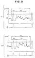
- Fig. 5 is a waveform chart showing signals obtained from the light-receiving section in the first embodiment;
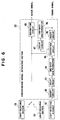
- Fig. 6 is a block diagram of an electric system;
- Fig. 7is a time chart illustrating the operations of the blocks shown in Fig. 6;
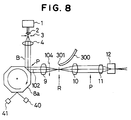
- Fig. 8 is a diagrammatic illustration of an optical system incorporated in a second embodiment of the present invention;
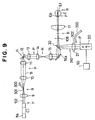
- Fig. 9 is a side elevational view of the optical system shown in Fig. 8; and
- Fig. 10 is a front elevational view of a diffusion reflective plate incorporated in the third embodiment.
- Embodiments of the present invention will be described with reference to the accompanying drawings.
- A first embodiment of the present invention is a scanning optical device of a so-called confocal type in which a light-receiving system makes use of a pair of movable mirrors commonly with an illumination system so that the light-receiving section receives the light reflected only by the illuminated portion of an eyeground as an examination object illuminated by the scanning light.
- More specifically, as shown in Figs. 1 and 2, the first embodiment of the scanning optical device of the present invention has a
laser oscillator 1 as a light source, a scanningoptical system 100,a light-receiving system which is partially common to thescanning illumination system 100, and a light-receivingsection 19. In these Figures, P represents a position which is conjugate with the pupil EP of the eye E as an examination object, while R represents a position which is conjugate with the eyeground Ef. - The
scanning illumination system 100 has alaser collimator 2 disposed in front of thelaser oscillator 1, a pin-hole 3 disposed at the front focal point of thelaser collimator 2, acollimator lens 4 the rear focal point of which is positioned on the pin-hole 3, and apolarization beam splitter 6 disposed in a collimated laser beam B formed by thecollimator lens 4. The terms "front" and "rear" are used in this specification to mean, respectively, the side of thelaser oscillator 1 adjacent to the eye E and the side of the same adjacent to the light-receivingsection 19. - The
scanning illumination system 100 further has apolygon mirror 8a disposed on the front side of thepolarization beam splitter 6 and capable of oscillating the beam for the scanning purpose, amagnification lens 9 arranged on the reflectionoptical axis 102 of the polygon mirror, a diffusionreflective plate 31 disposed at the front focal point of themagnification lens 9 and outside theoptical axis 102, and amagnification lens 10 which has the rear focus at the point where the extension plane of the scatteringreflective plate 31 crosses theoptical axis 102. A light-emittingelement 40 and a light-receivingelement 41 are disposed at one side of thepolygon mirror 8a so as to optically oppose each other through a reflective surface of thepolygon mirror 8a thereby to detect that all the reflective surfaces of the polygon mirror are directed in predetermined directions. The laser beam B flies in the direction of thearrow 104 when thepolygon mirror 8a rotates clockwise. - As shown in Fig. 2, the scanning illumination system further has a
relay lens 11 disposed in the path of a collimated laser beam B formed by themagnification lens 10, areflective mirror 12 obliquely arranged at the front focal point of therelay lens 11, afocus lens 13 having the rear focal point located on thereflective mirror 12, afocus lens 14 disposed in the collimated laser beam B formed by thefocus lens 14, arelay lens 15 for receiving the laser beam converged by saidfocus lens 14 and then diverged, so as to converge again the received diverged light, and a galvano-mirror 16 capable of rotating counter-clockwise thereby to enable the beam to scan an object. - The
scanning illumination system 100 further has anobjective lens 17 the rear focus of which is located at the point where the beam converged through therelay lens 15 is focused. Theobjective lens 17 is arranged to oppose the eye E as the examination object. Ep and Ef respectively represent the pupil and the eyeground of the eye E. - The diffusion
reflective plate 31 has adiffusion surface 31A andanti-reflection surfaces diffusing surface 31A, as will be seen from Fig. 3 which is an enlarged view around thereflective plate 31 and Fig. 4 which is a front elevational view of the same. The diffusingreflective plate 31 is fixed to thelens barrel 33 of themagnification lenses optical axis 102. As will be seen from Fig. 4, the diffusionreflective plate 31 is located on theline 32 of scan by the optical axis of the light from thepolygon mirror 8a. As will be seen from Fig. 4, the size of the diffusionreflective plate 31 is so determined as to correspond to a period L˝ which is within the period L of the scanning by the laser beam and which is before entering the effective period L′ of scan by the laser beam. Theanti-reflection surfaces reflective plate 31 may be a disk having a circular or an elliptical hole centered at the optical axis. - In operation of the
scanning illumination system 100, the laser beam from alaser oscillator 1 is collimated through thelaser collimator lens 2, the pin-hole 3 and thecollimator lens 3 and is reflected by the polygon mirror so as to scan in the direction of thearrow 104. The laser beam B is then relayed through therelay lenses lenses arrow 106 at each scan so that it scans the eyeground Ef. On the other hand, a part of the scanning laser beam passing through themagnification lens 9 is reflected by the diffusionreflective plate 31 so as to form a synchronizing signal,and traces the scanning illumination system backward. - The light-receiving
system 200 has a portion which is not common to thescanning illumination system 100. As shown in Fig. 1, this portion of the light-receivingsystem 200 includes ananalyzer 21 disposed on the reflectionoptical axis 202 of thedeflection beam splitter 6, acondenser lens 22 disposed at the front side of theanalyzer 21, a pin-hole 23 disposed at the front focal point of theanalyzer 21, and a light-receivingsection 19 disposed in front of the pin-hole 23. - In operation of the light-receiving
system 200, the laser beam containing an image signal reflected from the eyeground Ef and a synchronizing signal reflected by a diffusionreflective plate 31 is reflected by thepolygon mirror 8a and thepolarization beam splitter 6 and is introduced into theanalyzer 21 which delivers to the light-receivingsection 19 only the laser beam component of a specific deflection without no noise component. - A description will be given of the synchronization detection method for picking up a synchronizing signal from the signal derived from the light-receiving section. As shown in section (1) of Fig. 5, the signal derived from the light-receiving
section 19 contains a synchronizing signal produced by the diffusionreflective plate 31 and an image signal obtained from the eyeground EF. It is necessary to pick-up only the synchronizing from the signal obtained from the light-receivingsection 19. The periods TT, TT′, and TT˝ in this Figure correspond to the periods L,L′ and L˝ in Fig. 4. - It will be understood that the synchronizing signal TT˝ has a level higher than the image signal TT′; from the eyeground because it is received by the light-receiving
system 200 as a synchronizing light signal which is obtained directly from the laser beam B through diffusion and reflection performed by the diffusionreflective plate 31. It is therefore possible to pick-up the synchronizingsignal ②, by binarizing the signal at a level A which is higher than the level of theimage signal ① as shown in section (1) of Fig. 5. This method, however, is not practically recommended because, when a signal of a level higher than than A is contained in thesignal ① due to, for example, noise, it is difficult to discriminate the synchronizingsignal ② in the signal (2) obtained after the binarization. - According to the invention, therefore,
anti-reflection surfaces diffusion surface 31A so as to provide a distinction between the region of the synchronizing signal and the image signal, and the synchronizing signal is separated by means of a window signal. - A method of separation of the synchronizing signal and the image signal from each other will be described with reference to Fig. 6 which is a block diagram of a synchronizing
signal separating section 50 and Fig. 7 which is a timing chart illustrating timings of various signals. - The signal derived from the light-receiving
section 19 is shown in ① of Fig. 7. From this Figure, it will be understood that the region of the synchronizing signal and the region of the image signal are distinctively determined by virtue of the provision of theantireflection surfaces diffusion surface 31A. The signal for each reflection surface obtained from the light-receivingelement 41 is indicated by ② in Fig. 7. The separation of the synchronizing signal and the image signal from each other is conducted by using these two signals. - As will be seen from the block diagram in Fig. 6, the
signal ② of Fig. 7 derived from the light-receivingelement 41 is binarized by abinary circuit 42 so that a signal of a waveform indicated by ③ in Fig. 7 is obtained. This signal is then delayed by a time t₁ through adelay circuit 43, so that a delayedsignal ④ is obtained as shown in Fig. 7. - On the other hand, a synchronizing window signal, indicated at ⑤ in Fig. 7, is generated throughout a period t₂ by means of a one-
shot multivibrator 44. This window signal is input to theseparation circuit 45 together with thesignal ① of Fig. 7 derived from the light-receiving section, so that the synchronizing signal component is separated from thesignal ① as indicated at ⑥ in Fig. 7. This signal is then binarized by abinary circuit 46 so that the synchronizingsignal ⑦ is obtained as shown in Fig. 7. - On the other hand, the synchronizing signal is delayed by a time t₃ through a
delay circuit 47 so that asignal ⑧ is obtained as shown in Fig. 7, and animage window signal ⑨ is produced for a period t₄ by a one-shot multivibrator 48. This signal is input to aseparation circuit 49 together with thesignal ① from the light-receiving section,whereby an image signal component (10) is obtained. - Description will be given of second and third embodiments of the invention. These embodiments are scanning optical devices of so-called non-confocal type in which the light-receiving system does not make use of two mirrors of the illumination system so that the light-receiving system always receives the light reflected from the whole area of the eyeground Ef of the examined eye.
- The second embodiments are shown in Figs. 8 and 9, in which the components common to the first embodiment are denoted by the same reference numerals and detailed description of such components is omitted. This embodiment employs a
light guide 300 disposed at the front focal position of themagnification lens 9 at an offset from theoptical axis 104, i.e.,at the position corresponding to that of the diffusionreflective plate 31 of the first embodiment, with theincident end surface 301 of the light guide facing themagnification lens 9. - The light-receiving
system 310 includes ahalf mirror 30 obliquely arranged at a position between the galvano-mirror 16a and therelay lens 15,analyzer 21, and a light-receivingsection 20. The light emergingend surface 302 of thelight guide 300 faces the light-receivingsection 20. - The third embodiment employs a half mirror disposed at the front focal position of the
release lens 15 as shown in Fig. 9. A light-receiving section of the same construction as the light-receivingsection 310 of the second embodiment is disposed on the axis of the light reflected by the half mirror. In this case,the diffusionreflective plate 320 is disposed at a position R which is conjugate with the eyeground Ef of the examined eye. As shown in Fig. 10, the diffusionreflective plate 320 has a diffusionreflective surface 322A which is sized to cover the period N of scanning in the direction of an arrow 105 in the period L˝ before the effective scanning, in thearea 330 of the effective scanning, andanti-reflection surfaces diffusion reflection surface 322A. - Processing of signals in the second and third embodiments is conducted in the same manner as the first embodiment.
- According to the present invention, the image signal and the synchronizing signal are produced by a common illuminating light and are derived from the same light-receiving section, so that a synchronizing signal exactly synchronous with the image signal can be obtained by means of a simple arrangement.
Claims (6)
- A scanning optical device having a light source (1), a scanning illumination system (100) for scanning and illuminating an examination object (E) with the scanning light from said light source, and a light receiving system (200) having light receiving means (19) for receiving the light reflected from said examination object (E),
characterized by
a synchronous signal generating optical system (31; 300) adapted to guide scanning light from said scanning illumination system (100) to said light receiving means (19) without the intermediary of said examination object (E), and to generate a synchronizing signal; and a synchronizing signal extraction means (50) for picking up a synchronizing signal exactly synchronous with the image signal out of the signal derived from said light receiving means (19), which signal incorporates both the synchronizing signal generated at the light receiving means (19) via the synchronous signal generating optical system (300; 31) and the image signal generated at the light receiving means (19) from the light reflected from said examination object (E). - A scanning optical system according to Claim 1, wherein said synchronizing signal generating optical system (31; 300) has at least one optical member (31; 300) disposed at a position (R) conjugate with said examination object (E) on a line of scanning of said scanning light defined by said scanning illumination system (100) so that a portion of the light from said scanning illumination system (100) is guided to said light receiving means (19) without the intermediary of said examination object (E) when the scanning light is directed to said optical member (19).
- A scanning optical system according to Claim 2, wherein the light is guided to said light receiving means (19) through an optical fiber (300) having one end (301) positioned on said line of scanning.
- A scanning optical system according to Claim 2, wherein a reflective member (31) is disposed on said line of scanning so as to guide a portion of the scanning light to said light receiving means (19).
- A scanning optical system according to Claim 4, wherein said reflective member (31) is disposed on a light path common to said scanning illumination system (100) and said light receiving system (200), so that the scanning light is regularly reflected to return the light path so as to impinge upon the light receiving means (19).
- A scanning optical system according to Claim 5, wherein said reflective member (31) is disposed within a range between said examination object (E) and said scanning illumination system (100) and in which said scanning illumination system (100) and said light receiving system (200) are common.
Applications Claiming Priority (2)
| Application Number | Priority Date | Filing Date | Title |
|---|---|---|---|
| JP327472/88 | 1988-12-24 | ||
| JP63327472A JP2691359B2 (en) | 1988-12-24 | 1988-12-24 | Scanning optical device |
Publications (3)
| Publication Number | Publication Date |
|---|---|
| EP0376194A2 EP0376194A2 (en) | 1990-07-04 |
| EP0376194A3 EP0376194A3 (en) | 1991-03-20 |
| EP0376194B1 true EP0376194B1 (en) | 1995-03-08 |
Family
ID=18199540
Family Applications (1)
| Application Number | Title | Priority Date | Filing Date |
|---|---|---|---|
| EP89123771A Expired - Lifetime EP0376194B1 (en) | 1988-12-24 | 1989-12-22 | Scanning optical device |
Country Status (4)
| Country | Link |
|---|---|
| US (1) | US5107106A (en) |
| EP (1) | EP0376194B1 (en) |
| JP (1) | JP2691359B2 (en) |
| DE (1) | DE68921588T2 (en) |
Families Citing this family (2)
| Publication number | Priority date | Publication date | Assignee | Title |
|---|---|---|---|---|
| JPH10148893A (en) * | 1996-11-19 | 1998-06-02 | Brother Ind Ltd | Copier |
| JP6740999B2 (en) * | 2015-03-20 | 2020-08-19 | 株式会社ニコン | Pattern drawing device |
Family Cites Families (6)
| Publication number | Priority date | Publication date | Assignee | Title |
|---|---|---|---|---|
| US3465352A (en) * | 1966-05-11 | 1969-09-02 | Ncr Co | Information processing systems using lasers |
| JPS533833A (en) * | 1976-07-01 | 1978-01-13 | Fuji Photo Film Co Ltd | Synchronous signal generation in light beam scan |
| JPS6024624B2 (en) * | 1977-04-07 | 1985-06-13 | 富士写真フイルム株式会社 | Light beam scanning method |
| US4447723A (en) * | 1981-09-03 | 1984-05-08 | Excellon Industries | Scanning beam reference employing a retroreflective code means |
| US4616132A (en) * | 1984-05-29 | 1986-10-07 | Eastman Kodak Company | Synchronization apparatus for scanner |
| JPS6244712A (en) * | 1985-08-23 | 1987-02-26 | Fuji Photo Film Co Ltd | Synchronizing signal generating method |
-
1988
- 1988-12-24 JP JP63327472A patent/JP2691359B2/en not_active Expired - Fee Related
-
1989
- 1989-12-21 US US07/454,196 patent/US5107106A/en not_active Expired - Lifetime
- 1989-12-22 EP EP89123771A patent/EP0376194B1/en not_active Expired - Lifetime
- 1989-12-22 DE DE68921588T patent/DE68921588T2/en not_active Expired - Fee Related
Also Published As
| Publication number | Publication date |
|---|---|
| EP0376194A3 (en) | 1991-03-20 |
| EP0376194A2 (en) | 1990-07-04 |
| US5107106A (en) | 1992-04-21 |
| JPH02171714A (en) | 1990-07-03 |
| DE68921588T2 (en) | 1995-12-07 |
| DE68921588D1 (en) | 1995-04-13 |
| JP2691359B2 (en) | 1997-12-17 |
Similar Documents
| Publication | Publication Date | Title |
|---|---|---|
| US7348528B2 (en) | Distance measuring system | |
| US4930896A (en) | Surface structure measuring apparatus | |
| KR880006659A (en) | Optical pickup | |
| JPS63155114A (en) | Scan type microscope | |
| EP1892499A3 (en) | Atomic force microscope for generating a small incident beam spot | |
| EP0326354A2 (en) | Apparatus for reading information out of an optical recording medium | |
| FR2646245B1 (en) | OPTICAL READING DEVICE FOR OPTICAL RECORDING MEDIUM | |
| US5251011A (en) | Displacement detection system | |
| US4851913A (en) | Picture recording apparatus | |
| US5107106A (en) | Scanning and detecting optical device | |
| US5130533A (en) | Device for measuring backscattered radiation using a frequency selective element | |
| JP2571859B2 (en) | Scanning optical microscope | |
| JPH05224127A (en) | Confocal scanning type differential interfere microscope | |
| EP0718656B1 (en) | Transmission type confocal laser microscope | |
| EP0837415A1 (en) | Scanning system with radially directed, multiple-reading scanning units | |
| JPH1195114A (en) | Scanning optical microscope device | |
| KR100455835B1 (en) | Pick-Up Optical System | |
| JP2613130B2 (en) | Confocal scanning phase contrast microscope | |
| JPH07182666A (en) | Optical pickup system | |
| JP3180019B2 (en) | Document edge detection device | |
| JPS61175611A (en) | Synchronous photodetector | |
| JP3325096B2 (en) | Scanning optical microscope | |
| JPH07105547A (en) | Automatic focusing mechanism | |
| JPH10133117A (en) | Microscope with focus detection device | |
| JPH03131811A (en) | Confocal scanning type transmission microscope |
Legal Events
| Date | Code | Title | Description |
|---|---|---|---|
| PUAI | Public reference made under article 153(3) epc to a published international application that has entered the european phase |
Free format text: ORIGINAL CODE: 0009012 |
|
| AK | Designated contracting states |
Kind code of ref document: A2 Designated state(s): DE FR GB |
|
| PUAL | Search report despatched |
Free format text: ORIGINAL CODE: 0009013 |
|
| AK | Designated contracting states |
Kind code of ref document: A3 Designated state(s): DE FR GB |
|
| 17P | Request for examination filed |
Effective date: 19910906 |
|
| 17Q | First examination report despatched |
Effective date: 19930813 |
|
| GRAA | (expected) grant |
Free format text: ORIGINAL CODE: 0009210 |
|
| AK | Designated contracting states |
Kind code of ref document: B1 Designated state(s): DE FR GB |
|
| REF | Corresponds to: |
Ref document number: 68921588 Country of ref document: DE Date of ref document: 19950413 |
|
| ET | Fr: translation filed | ||
| PLBE | No opposition filed within time limit |
Free format text: ORIGINAL CODE: 0009261 |
|
| STAA | Information on the status of an ep patent application or granted ep patent |
Free format text: STATUS: NO OPPOSITION FILED WITHIN TIME LIMIT |
|
| 26N | No opposition filed | ||
| REG | Reference to a national code |
Ref country code: GB Ref legal event code: IF02 |
|
| PGFP | Annual fee paid to national office [announced via postgrant information from national office to epo] |
Ref country code: GB Payment date: 20051208 Year of fee payment: 17 |
|
| PGFP | Annual fee paid to national office [announced via postgrant information from national office to epo] |
Ref country code: FR Payment date: 20051222 Year of fee payment: 17 |
|
| PGFP | Annual fee paid to national office [announced via postgrant information from national office to epo] |
Ref country code: DE Payment date: 20051228 Year of fee payment: 17 |
|
| PG25 | Lapsed in a contracting state [announced via postgrant information from national office to epo] |
Ref country code: DE Free format text: LAPSE BECAUSE OF NON-PAYMENT OF DUE FEES Effective date: 20070703 |
|
| GBPC | Gb: european patent ceased through non-payment of renewal fee |
Effective date: 20061222 |
|
| REG | Reference to a national code |
Ref country code: FR Ref legal event code: ST Effective date: 20070831 |
|
| PG25 | Lapsed in a contracting state [announced via postgrant information from national office to epo] |
Ref country code: GB Free format text: LAPSE BECAUSE OF NON-PAYMENT OF DUE FEES Effective date: 20061222 |
|
| PG25 | Lapsed in a contracting state [announced via postgrant information from national office to epo] |
Ref country code: FR Free format text: LAPSE BECAUSE OF NON-PAYMENT OF DUE FEES Effective date: 20070102 |