EP0375705B1 - A lifting truck with a telescopic lifting arm - Google Patents
A lifting truck with a telescopic lifting arm Download PDFInfo
- Publication number
- EP0375705B1 EP0375705B1 EP88907051A EP88907051A EP0375705B1 EP 0375705 B1 EP0375705 B1 EP 0375705B1 EP 88907051 A EP88907051 A EP 88907051A EP 88907051 A EP88907051 A EP 88907051A EP 0375705 B1 EP0375705 B1 EP 0375705B1
- Authority
- EP
- European Patent Office
- Prior art keywords
- truck
- cab
- lifting
- arm
- lifting arm
- Prior art date
- Legal status (The legal status is an assumption and is not a legal conclusion. Google has not performed a legal analysis and makes no representation as to the accuracy of the status listed.)
- Revoked
Links
Images

Classifications
-
- B—PERFORMING OPERATIONS; TRANSPORTING
- B66—HOISTING; LIFTING; HAULING
- B66F—HOISTING, LIFTING, HAULING OR PUSHING, NOT OTHERWISE PROVIDED FOR, e.g. DEVICES WHICH APPLY A LIFTING OR PUSHING FORCE DIRECTLY TO THE SURFACE OF A LOAD
- B66F9/00—Devices for lifting or lowering bulky or heavy goods for loading or unloading purposes
- B66F9/06—Devices for lifting or lowering bulky or heavy goods for loading or unloading purposes movable, with their loads, on wheels or the like, e.g. fork-lift trucks
- B66F9/065—Devices for lifting or lowering bulky or heavy goods for loading or unloading purposes movable, with their loads, on wheels or the like, e.g. fork-lift trucks non-masted
- B66F9/0655—Devices for lifting or lowering bulky or heavy goods for loading or unloading purposes movable, with their loads, on wheels or the like, e.g. fork-lift trucks non-masted with a telescopic boom
Definitions
- the present invention relates to a lifting truck according to the preamble of the single claim.
- a lifting truck of the above specified type is known from DE-A-2.739.537.
- the engine necessarily extends transversely towards the driver's cab for such an extent that the lifting arm lies upon the engine housing, whereby:
- a lifting truck in which the engine is longitudinally placed is known from US-E-30021.
- the engine is longitudinally placed in the middle portion of the truck under a well which is arranged to receive the lifting arm in its lower position. Therefore, also in this truck the lifting arm lies upon the engine housing, which implies the same drawbacks listed above.
- the object of the present invention is to provide a lifting truck of the type specified above in which a lower center of gravity and a greater lateral and rearwardly angle of sight is achieved.
- the present invention provides a lifting truck of the type specified above which is characterised by the feature defined in the characterizing part of the single claim.
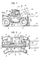
- a lifting truck generally indicated 2 includes a support platform structure 4 provided with front and rear wheels 6 and 8 respectively, and with a telescopic lifting arm 22, articulated to the rear end of an upright 18 carried by the structure 4.
- the platform 4 supports a driving cab 10 situated on one side of the platform 4 and to one side of the longitudinal axis A-A of the truck.
- the platform On the opposite side of the axis A-A to the driving cab, the platform supports a housing 12 in which a longitudinally-extending internal combustion engine 16, provided with a vertically-directed exhaust pipe 20, is housed.
- the housing 12 is positioned at a distance from the cab 10 so as to define with the cab a space 14 which is at least as wide as the lifting arm 22.
- the lifting arm 22 is articulated about a horizontal pin 22a transverse the axis A-A and situated at a level such that the arm is partly accomodated in the space 14 in its completely lowered position.
- the telescopic arm 22 is illustrated in its completely retracted position, being shown in broken outline in a partially raised position, and in continuous outline in its completely lowered position in which it extends longitudinally adjacent the cab 10 in the space 14 and does not interfere with the view of the operator working in the driving cab.
- the top of the engine housing 12, the axis of the articulation pin 22a of the lifting arm, and the top of the lifting arm 22 in its completely lowered position are all situated at a lower level than the line of sight of the operator working in the cab.
- the lifting arm 22 is pivoted about the pin 22a by means of a hydraulic jack 24 the lower part of which is articulated at 24a to the central part of the platform 4.
- a hydraulic jack 24 the lower part of which is articulated at 24a to the central part of the platform 4.
- the inner slidable end element 26 of the telescopic arm 22 carries a head 28 to which an implement 32, which is pivoted by means of a jack 24, is articulated about a pin 30.
- the implement 32 is constituted by a forked platform; this platform may, however, be replaced by other types of implement, for example, by a bucket.
- the variant illustrated in Figures 4 and 5 differs from the embodiment described above in that the jack 24 which causes the pivoting of the lifting arm 22 is articulated at the rear to the chassis of the truck about a pin 24 at the base of the upright 18, and is inclined forwardly and upwardly when the arm 22 is in the lowered position. Moreover, the exhaust pipe 20 is directed towards the rear part of the vehicle with a slight upward inclination, instead of being vertical.
Abstract
Description
- The present invention relates to a lifting truck according to the preamble of the single claim. A lifting truck of the above specified type is known from DE-A-2.739.537.
- In the lifting truck according to DE-A-2.739.537 the internal combustion engine is transversely placed, that is with its shaft perpendicular to the longitudinal axis of the vehicle.
- Due to its overall dimensions, the engine necessarily extends transversely towards the driver's cab for such an extent that the lifting arm lies upon the engine housing, whereby:
- a) the center of gravity of the lifting arm is located, in the lowered position of the arm, at a substantial height from the ground, thereby impairing the stability of the truck,
- b) the lateral angle of sight beneath the horizontal plane passing through the center of sight of the operator working in the cab is very small when the lifting arm is in its lowered position. Moreover, said angle is still reduced when the lifting arm is slightly raised to maintain a load carried by the arm raised from the ground for allowing its displacement, that is in a condition in which the greatest visibility is required,
- c) the pivot pin for the lifting arm must be supported by the truck structure at a substantial height from the ground, which limits the rear sight angle beneath the horizontal plane passing through the center of sight of the operator.
- A lifting truck in which the engine is longitudinally placed is known from US-E-30021. However, in said lifting truck the engine is longitudinally placed in the middle portion of the truck under a well which is arranged to receive the lifting arm in its lower position. Therefore, also in this truck the lifting arm lies upon the engine housing, which implies the same drawbacks listed above.
- The object of the present invention is to provide a lifting truck of the type specified above in which a lower center of gravity and a greater lateral and rearwardly angle of sight is achieved. In order to achieve this object the present invention provides a lifting truck of the type specified above which is characterised by the feature defined in the characterizing part of the single claim.
- Further characteristics and advantages of the truck according to the invention will become clear in the course of the detailed description which follows with reference to the appended drawings, provided by way of non-limiting example, in which:
- Figure 1 is a side elevational view of a fork-lift truck;
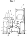
- Figure 2 is a front elevational view of the truck of Figure 1,
- Figure 3 is a view of the truck of Figure 1 from above,
- Figure 4 is a view similar to Figure 1 of a variant, and
- Figure 5 is a perspective view of the vehicle shown in Figure 4.
- With reference to Figures 1 to 3, a lifting truck, generally indicated 2, includes a
support platform structure 4 provided with front andrear wheels telescopic lifting arm 22, articulated to the rear end of an upright 18 carried by thestructure 4. Theplatform 4 supports adriving cab 10 situated on one side of theplatform 4 and to one side of the longitudinal axis A-A of the truck. - On the opposite side of the axis A-A to the driving cab, the platform supports a
housing 12 in which a longitudinally-extendinginternal combustion engine 16, provided with a vertically-directedexhaust pipe 20, is housed. Thehousing 12 is positioned at a distance from thecab 10 so as to define with the cab aspace 14 which is at least as wide as thelifting arm 22. - The
lifting arm 22 is articulated about a horizontal pin 22a transverse the axis A-A and situated at a level such that the arm is partly accomodated in thespace 14 in its completely lowered position. In Figure 1, thetelescopic arm 22 is illustrated in its completely retracted position, being shown in broken outline in a partially raised position, and in continuous outline in its completely lowered position in which it extends longitudinally adjacent thecab 10 in thespace 14 and does not interfere with the view of the operator working in the driving cab. In particular, the top of the engine housing 12, the axis of the articulation pin 22a of the lifting arm, and the top of thelifting arm 22 in its completely lowered position are all situated at a lower level than the line of sight of the operator working in the cab. - The
lifting arm 22 is pivoted about the pin 22a by means of ahydraulic jack 24 the lower part of which is articulated at 24a to the central part of theplatform 4. When thearm 22 is in the lowered position, thejack 24 is inclined forwardly and downwardly. - The inner
slidable end element 26 of thetelescopic arm 22 carries ahead 28 to which animplement 32, which is pivoted by means of ajack 24, is articulated about apin 30. - In the embodiment illustrated, the
implement 32 is constituted by a forked platform; this platform may, however, be replaced by other types of implement, for example, by a bucket. - The variant illustrated in Figures 4 and 5 differs from the embodiment described above in that the
jack 24 which causes the pivoting of thelifting arm 22 is articulated at the rear to the chassis of the truck about apin 24 at the base of the upright 18, and is inclined forwardly and upwardly when thearm 22 is in the lowered position. Moreover, theexhaust pipe 20 is directed towards the rear part of the vehicle with a slight upward inclination, instead of being vertical. - By virtue of the characteristics of the truck according to the invention, not only the operator's view to the side and to the rear but also the characteristics of stability, manoeuvrability, accessibility, thrust force and habitability of the truck are improved. In fact, by virtue of the above-described positioning of the engine and the lifting arm, there is also a substantial lowering of the centre of gravity of the truck with obvious advantages in terms of its aforementioned characteristics and of its safety in use.
Claims (1)
- A lifting truck of the type comprising a wheeled structure carrying a lifting arm (22) articulated to the rear of the structure about a horizontal axis perpendicular to the longitudinal axis (A-A) of the truck, an internal combustion engine (16) supported by the structure for propulsion of the truck and for the operation of the arm (22), and an operating and driving cab (10) situated on one side of the structure to one side of the longitudinal axis (A-A), the internal combustion engine (16) being disposed in a housing (12) which is situated on the opposite side of the longitudinal axis (A-A) to the cab (10), characterized in that the housing (12) is spaced from the cab so as to define with the cab a space (14) having a width at least equal to the width of the lifting arm (22), the lifting arm being articulated to the structure of the truck in such a position that, in its completely lowered position, it is partly accommodated in the space (14) so as not to interfere with the view of the operator working in the driving cab, and in that the internal combustion engine (16) is longitudinally placed in said housing (12), that is with its shaft parallel to the longitudinal axis (A-A) of the truck.
Priority Applications (1)
| Application Number | Priority Date | Filing Date | Title |
|---|---|---|---|
| AT88907051T ATE82007T1 (en) | 1987-07-27 | 1988-07-19 | LIFTING TROLLEY WITH A TELESCOPIC LIFTING ARM. |
Applications Claiming Priority (2)
| Application Number | Priority Date | Filing Date | Title |
|---|---|---|---|
| IT8753559U IT212207Z2 (en) | 1987-07-27 | 1987-07-27 | TELESCOPIC ARM FORKLIFT |
| IT5355987 | 1987-07-27 |
Publications (2)
| Publication Number | Publication Date |
|---|---|
| EP0375705A1 EP0375705A1 (en) | 1990-07-04 |
| EP0375705B1 true EP0375705B1 (en) | 1992-11-04 |
Family
ID=11283681
Family Applications (1)
| Application Number | Title | Priority Date | Filing Date |
|---|---|---|---|
| EP88907051A Revoked EP0375705B1 (en) | 1987-07-27 | 1988-07-19 | A lifting truck with a telescopic lifting arm |
Country Status (7)
| Country | Link |
|---|---|
| US (1) | US5199861A (en) |
| EP (1) | EP0375705B1 (en) |
| JP (1) | JP2559831B2 (en) |
| ES (1) | ES1013890Y (en) |
| IT (1) | IT212207Z2 (en) |
| RU (1) | RU1831453C (en) |
| WO (1) | WO1989000972A1 (en) |
Cited By (1)
| Publication number | Priority date | Publication date | Assignee | Title |
|---|---|---|---|---|
| US5836733A (en) * | 1994-07-15 | 1998-11-17 | J.C. Bamford Excavators Limited | Material-handling vehicle |
Families Citing this family (39)
| Publication number | Priority date | Publication date | Assignee | Title |
|---|---|---|---|---|
| IT1236419B (en) * | 1989-12-15 | 1993-03-01 | Manitou Costr Ind Srl | SELF-PROPELLED ELEVATOR WITH BACKHOE. |
| CA2009968C (en) * | 1990-02-13 | 1996-06-25 | Giovanni Bentivoglio | Boom operated fork truck |
| GB2292932B (en) * | 1992-06-30 | 1996-10-02 | Caterpillar Inc | Material handling machine |
| IT228665Y1 (en) * | 1992-07-29 | 1998-05-07 | Dieci Flli | TELESCOPIC ARM FORKLIFT |
| GB2291384A (en) * | 1994-07-15 | 1996-01-24 | Bamford Excavators Ltd | Material-handling vehicle with a loader arm and transverse engine |
| CA2158232C (en) † | 1994-09-14 | 2001-08-07 | Marcel-Claude Braud | Motor trolley with telescoping arm |
| AU2971197A (en) * | 1996-06-05 | 1998-01-05 | New Holland Uk Limited | Telescopic handler |
| US5931255A (en) * | 1997-05-09 | 1999-08-03 | Caterpillar Inc. | Power transfer arrangement for a machine |
| US6439827B1 (en) * | 1997-07-08 | 2002-08-27 | J C Bamford Excavators Limited | Load handling vehicle |
| US6024232A (en) * | 1997-07-24 | 2000-02-15 | Kalmar Industries Sverige Ab | Boom truck |
| US5944130A (en) * | 1997-11-04 | 1999-08-31 | Caterpillar Inc. | Trunnion mounted drive train arrangement |
| ITTO980271A1 (en) * | 1998-03-27 | 1999-09-27 | Merlo Ind Metalmecc | VEHICLE WITH LIFTING ARM, USED AS AGRICULTURAL MACHINE |
| ITTO980268A1 (en) | 1998-03-27 | 1999-09-27 | Merlo Ind Metalmecc | VEHICLE WITH LIFTING ARM, EQUIPPED WITH A POWER TAKE OPERATED BY A MECHANICAL TRANSMISSION |
| ITTO980270A1 (en) | 1998-03-27 | 1999-09-27 | Merlo Ind Metalmecc | VEHICLE WITH LIFTING ARM WITH INCLINED MOTOR COMPARED TO THE LONGITUDINAL AXIS OF THE VEHICLE |
| GB2336255B (en) | 1998-04-08 | 2002-03-13 | Gen Domestic Appliances Ltd | Cooking appliance energy regulator |
| GB9807532D0 (en) | 1998-04-09 | 1998-06-10 | Bamford Excavators Ltd | Material-handling vehicle |
| GB9807538D0 (en) * | 1998-04-09 | 1998-06-10 | Bamford Excavators Ltd | Material-handling vehicle |
| GB9807528D0 (en) | 1998-04-09 | 1998-06-10 | Bamford Excavators Ltd | Material-handling vehicle |
| GB9807530D0 (en) | 1998-04-09 | 1998-06-10 | Bamford Excavators Ltd | Material-handling vehicle |
| IT1304978B1 (en) * | 1998-09-10 | 2001-04-05 | Merlo Ind Metalmecc | VEHICLE USABLE AS LIFT AND AGRICULTURAL TRACTOR. |
| FR2788759B1 (en) | 1999-01-27 | 2001-03-23 | Sambron | DEVICE FOR CONTROLLING THE MOVEMENT OF A CARRIER STRUCTURE OF A ROLLING MACHINE AND A ROLLING MACHINE INCORPORATING THE SAME |
| FR2797625B1 (en) | 1999-08-18 | 2001-11-02 | Sambron | DEVICE FOR CORRECTING A TILT FOR A TWO-AXLE PLATFORM |
| GB9921800D0 (en) | 1999-09-16 | 1999-11-17 | Bamford Excavators Ltd | Material -handling vehicle |
| IT1311436B1 (en) * | 1999-12-17 | 2002-03-12 | New Holland Italia Spa | EARTH MOVING MACHINE. |
| WO2003080497A1 (en) * | 2002-03-22 | 2003-10-02 | Hitachi Construction Machinery Co., Ltd. | Self-propelled working machine |
| DE60315019T2 (en) * | 2002-05-03 | 2008-04-10 | Clark Equipment Co. | REMOVABLE HYDRAULIC TERMINAL |
| DE60209877T2 (en) | 2002-05-15 | 2006-11-02 | Komatsu Utility Europe S.P.A., Noventa Vicentina | Lifting vehicle with telescopic lifting arm |
| US7383906B2 (en) * | 2002-08-29 | 2008-06-10 | Jlg Industries, Inc. | Rotatable and telescopic work machine |
| JP2004203553A (en) | 2002-12-25 | 2004-07-22 | Hitachi Constr Mach Co Ltd | Mobile type working machine |
| WO2004083099A1 (en) * | 2003-03-18 | 2004-09-30 | Hitachi Construction Machinery Co., Ltd. | Self-propelled working machine |
| DE102004018667B4 (en) * | 2004-04-17 | 2007-07-12 | Noell Mobile Systems & Cranes Gmbh | Stacking and transport vehicle for container handling sites and warehouses |
| GB2447229B (en) | 2007-03-07 | 2011-11-02 | Niftylift Ltd | Mobile work platform with multiple mode drive system |
| US8047759B2 (en) * | 2009-03-06 | 2011-11-01 | Wazee Group, Inc. | Manual forklift apparatus and methods |
| CA2791616C (en) * | 2010-03-05 | 2016-04-19 | Paul Seales | Truck-mounted crane |
| USD668271S1 (en) * | 2011-10-31 | 2012-10-02 | J.C. Bamford Excavators Limited | Telehandler |
| USD758039S1 (en) * | 2014-09-04 | 2016-05-31 | Liebherr-Werk Nenzing Gmbh | Reachstacker |
| USD756057S1 (en) * | 2014-09-04 | 2016-05-10 | Liebherr-Werk Nenzing Gmbh | Reachstacker |
| USD903222S1 (en) * | 2019-03-26 | 2020-11-24 | J.C. Bamford Excavators Limited | Machine for earth-moving, material handling, lifting, and/or construction |
| USD1011382S1 (en) * | 2021-06-01 | 2024-01-16 | Jiangsu Xcmg Construction Machinery Research Institute Ltd. | Aerial work platform vehicle |
Family Cites Families (10)
| Publication number | Priority date | Publication date | Assignee | Title |
|---|---|---|---|---|
| US2591584A (en) * | 1947-06-13 | 1952-04-01 | Jeffrey Mfg Co | Wheel suspension and steering assembly |
| DE2301777C3 (en) * | 1973-01-15 | 1982-01-21 | Gewerkschaft Eisenhütte Westfalia, 4670 Lünen | Self-propelled loading machine |
| US3836025A (en) * | 1973-05-21 | 1974-09-17 | Loed Corp | Material-handling machine |
| DE2545427B2 (en) * | 1974-10-12 | 1979-05-03 | Liner Concrete Machinery Co. Ltd., Gateshead, Durham (Grossbritannien) | Vehicle for moving loads |
| US3967744A (en) * | 1975-02-18 | 1976-07-06 | Clark Equipment Company | Extensible reach load lifting mechanism |
| DE2739537A1 (en) * | 1976-09-03 | 1978-03-09 | Loed Corp | Pivoted lifting fork on telescopic jib - has drive rotating fork sideways about two separate pivoting axes |
| US4210219A (en) * | 1977-09-22 | 1980-07-01 | Standard Manufacturing Co., Inc. | Undercarriage for adverse terrain vehicle |
| US4345873A (en) * | 1980-06-02 | 1982-08-24 | Wymore Roger S | Material handling vehicle |
| US4382743A (en) * | 1981-02-23 | 1983-05-10 | Newell Lawrence H | Loading apparatus with a tiltable and extendable fork carriage mounted thereon |
| FR2545468A1 (en) * | 1983-05-03 | 1984-11-09 | Koehring Co | Device for mounting a fork on a forklift truck and unloading method using a forklift truck comprising such a device |
-
1987
- 1987-07-27 IT IT8753559U patent/IT212207Z2/en active
-
1988
- 1988-07-19 WO PCT/EP1988/000647 patent/WO1989000972A1/en not_active Application Discontinuation
- 1988-07-19 JP JP63506191A patent/JP2559831B2/en not_active Expired - Lifetime
- 1988-07-19 US US07/458,686 patent/US5199861A/en not_active Expired - Fee Related
- 1988-07-19 EP EP88907051A patent/EP0375705B1/en not_active Revoked
- 1988-07-26 ES ES19889001099U patent/ES1013890Y/en not_active Expired - Lifetime
-
1990
- 1990-01-26 RU SU904743028A patent/RU1831453C/en active
Cited By (1)
| Publication number | Priority date | Publication date | Assignee | Title |
|---|---|---|---|---|
| US5836733A (en) * | 1994-07-15 | 1998-11-17 | J.C. Bamford Excavators Limited | Material-handling vehicle |
Also Published As
| Publication number | Publication date |
|---|---|
| IT212207Z2 (en) | 1989-07-04 |
| RU1831453C (en) | 1993-07-30 |
| US5199861A (en) | 1993-04-06 |
| WO1989000972A1 (en) | 1989-02-09 |
| JP2559831B2 (en) | 1996-12-04 |
| ES1013890U (en) | 1991-02-01 |
| EP0375705A1 (en) | 1990-07-04 |
| IT8753559V0 (en) | 1987-07-27 |
| JPH03501115A (en) | 1991-03-14 |
| ES1013890Y (en) | 1991-07-16 |
Similar Documents
| Publication | Publication Date | Title |
|---|---|---|
| EP0375705B1 (en) | A lifting truck with a telescopic lifting arm | |
| US4718814A (en) | Forklift variable reach mechanism | |
| EP1538888B1 (en) | Upper hitch link | |
| JPH11236192A (en) | Industrial vehicle provided with battery block | |
| US4790711A (en) | Self-loading and unloading truck trailer assembly | |
| WO1998032928A1 (en) | Improvements to tractor shovels | |
| CA2328938A1 (en) | Transportable lift truck with telescopic lifting arm | |
| US4640662A (en) | Fork lift attachment for tractor | |
| GB2161784A (en) | Handling or working vehicle | |
| US4345873A (en) | Material handling vehicle | |
| US6116843A (en) | Fork lift truck, adapted to be loaded on the rear of a carrying vehicle | |
| CA1282038C (en) | Device for removably attaching front loader to vehicle | |
| ES2217528T3 (en) | VEHICLE PROVIDED WITH A LIFTING FEATHER, WHICH CAN BE USED AS AN AGRICULTURAL MACHINE. | |
| KR19990086995A (en) | Reinforcement frame of working car | |
| US6916148B2 (en) | Load handling vehicle | |
| US4437696A (en) | Movable truck bumper | |
| US6957705B2 (en) | Loader linkage | |
| AU2001269260A1 (en) | Load handling vehicle | |
| US6910544B2 (en) | Work machine arrangement | |
| US4101040A (en) | Vehicle for transporting palletized loads | |
| US6079938A (en) | Combination step/stop arrangement for a skid steer loader | |
| US6098719A (en) | Parallelogram boom devices for mounting agricultural implements to short wheel base tractors and adjusting implement position relative to ground | |
| US6439827B1 (en) | Load handling vehicle | |
| EP0543791A1 (en) | A lifting vehicle for stacking loads | |
| EP0286301A1 (en) | Vehicle-mountable access lift |
Legal Events
| Date | Code | Title | Description |
|---|---|---|---|
| PUAI | Public reference made under article 153(3) epc to a published international application that has entered the european phase |
Free format text: ORIGINAL CODE: 0009012 |
|
| 17P | Request for examination filed |
Effective date: 19900202 |
|
| AK | Designated contracting states |
Kind code of ref document: A1 Designated state(s): AT BE CH DE FR GB IT LI NL SE |
|
| 17Q | First examination report despatched |
Effective date: 19910404 |
|
| GRAA | (expected) grant |
Free format text: ORIGINAL CODE: 0009210 |
|
| AK | Designated contracting states |
Kind code of ref document: B1 Designated state(s): AT BE CH DE FR GB IT LI NL SE |
|
| REF | Corresponds to: |
Ref document number: 82007 Country of ref document: AT Date of ref document: 19921115 Kind code of ref document: T |
|
| ITF | It: translation for a ep patent filed |
Owner name: JACOBACCI & PERANI S.P.A. |
|
| REF | Corresponds to: |
Ref document number: 3875739 Country of ref document: DE Date of ref document: 19921210 |
|
| ET | Fr: translation filed | ||
| PLBI | Opposition filed |
Free format text: ORIGINAL CODE: 0009260 |
|
| 26 | Opposition filed |
Opponent name: MANITOU BF, SOCIETE ANONYME Effective date: 19930527 |
|
| PLBI | Opposition filed |
Free format text: ORIGINAL CODE: 0009260 |
|
| NLR1 | Nl: opposition has been filed with the epo |
Opponent name: MANITOU BF, S.A. |
|
| 26 | Opposition filed |
Opponent name: FDI-SAMBRON Effective date: 19930803 Opponent name: ATRIX LIMITED Effective date: 19930802 Opponent name: MANITOU BF, SOCIETE ANONYME Effective date: 19930527 |
|
| NLR1 | Nl: opposition has been filed with the epo |
Opponent name: FDI-SAMBRON Opponent name: ATRIX LIMITED |
|
| EAL | Se: european patent in force in sweden |
Ref document number: 88907051.2 |
|
| RDAH | Patent revoked |
Free format text: ORIGINAL CODE: EPIDOS REVO |
|
| APAC | Appeal dossier modified |
Free format text: ORIGINAL CODE: EPIDOS NOAPO |
|
| APAE | Appeal reference modified |
Free format text: ORIGINAL CODE: EPIDOS REFNO |
|
| APAC | Appeal dossier modified |
Free format text: ORIGINAL CODE: EPIDOS NOAPO |
|
| PGFP | Annual fee paid to national office [announced via postgrant information from national office to epo] |
Ref country code: SE Payment date: 20010629 Year of fee payment: 14 |
|
| PGFP | Annual fee paid to national office [announced via postgrant information from national office to epo] |
Ref country code: AT Payment date: 20010706 Year of fee payment: 14 |
|
| PGFP | Annual fee paid to national office [announced via postgrant information from national office to epo] |
Ref country code: GB Payment date: 20010713 Year of fee payment: 14 Ref country code: CH Payment date: 20010713 Year of fee payment: 14 |
|
| PGFP | Annual fee paid to national office [announced via postgrant information from national office to epo] |
Ref country code: DE Payment date: 20010718 Year of fee payment: 14 |
|
| PGFP | Annual fee paid to national office [announced via postgrant information from national office to epo] |
Ref country code: NL Payment date: 20010719 Year of fee payment: 14 |
|
| PGFP | Annual fee paid to national office [announced via postgrant information from national office to epo] |
Ref country code: FR Payment date: 20010731 Year of fee payment: 14 |
|
| PGFP | Annual fee paid to national office [announced via postgrant information from national office to epo] |
Ref country code: BE Payment date: 20010809 Year of fee payment: 14 |
|
| APAC | Appeal dossier modified |
Free format text: ORIGINAL CODE: EPIDOS NOAPO |
|
| RDAG | Patent revoked |
Free format text: ORIGINAL CODE: 0009271 |
|
| STAA | Information on the status of an ep patent application or granted ep patent |
Free format text: STATUS: PATENT REVOKED |
|
| REG | Reference to a national code |
Ref country code: CH Ref legal event code: PL |
|
| 27W | Patent revoked |
Effective date: 20011120 |
|
| GBPR | Gb: patent revoked under art. 102 of the ep convention designating the uk as contracting state |
Free format text: 20011120 |
|
| NLR2 | Nl: decision of opposition | ||
| NLR2 | Nl: decision of opposition |
Effective date: 20011120 |
|
| APAH | Appeal reference modified |
Free format text: ORIGINAL CODE: EPIDOSCREFNO |