EP0375687B1 - Thyristor on-load change-over switch - Google Patents
Thyristor on-load change-over switch Download PDFInfo
- Publication number
- EP0375687B1 EP0375687B1 EP88905150A EP88905150A EP0375687B1 EP 0375687 B1 EP0375687 B1 EP 0375687B1 EP 88905150 A EP88905150 A EP 88905150A EP 88905150 A EP88905150 A EP 88905150A EP 0375687 B1 EP0375687 B1 EP 0375687B1
- Authority
- EP
- European Patent Office
- Prior art keywords
- load
- change
- contact
- switch
- over
- Prior art date
- Legal status (The legal status is an assumption and is not a legal conclusion. Google has not performed a legal analysis and makes no representation as to the accuracy of the status listed.)
- Expired - Lifetime
Links
- 238000004804 winding Methods 0.000 claims abstract description 34
- 230000007704 transition Effects 0.000 claims abstract description 6
- 229920000136 polysorbate Polymers 0.000 claims 1
- 230000001105 regulatory effect Effects 0.000 abstract description 4
- 230000015556 catabolic process Effects 0.000 abstract 1
- 238000010276 construction Methods 0.000 abstract 1
- 238000011109 contamination Methods 0.000 abstract 1
- 238000000034 method Methods 0.000 description 8
- 238000010079 rubber tapping Methods 0.000 description 8
- 239000004065 semiconductor Substances 0.000 description 7
- 238000009795 derivation Methods 0.000 description 6
- 230000001360 synchronised effect Effects 0.000 description 4
- 230000003628 erosive effect Effects 0.000 description 2
- 230000007257 malfunction Effects 0.000 description 2
- 230000000903 blocking effect Effects 0.000 description 1
- 238000001514 detection method Methods 0.000 description 1
Images


Classifications
-
- H—ELECTRICITY
- H01—ELECTRIC ELEMENTS
- H01H—ELECTRIC SWITCHES; RELAYS; SELECTORS; EMERGENCY PROTECTIVE DEVICES
- H01H9/00—Details of switching devices, not covered by groups H01H1/00 - H01H7/00
- H01H9/0005—Tap change devices
-
- H—ELECTRICITY
- H01—ELECTRIC ELEMENTS
- H01F—MAGNETS; INDUCTANCES; TRANSFORMERS; SELECTION OF MATERIALS FOR THEIR MAGNETIC PROPERTIES
- H01F29/00—Variable transformers or inductances not covered by group H01F21/00
- H01F29/02—Variable transformers or inductances not covered by group H01F21/00 with tappings on coil or winding; with provision for rearrangement or interconnection of windings
- H01F29/04—Variable transformers or inductances not covered by group H01F21/00 with tappings on coil or winding; with provision for rearrangement or interconnection of windings having provision for tap-changing without interrupting the load current
-
- H—ELECTRICITY
- H01—ELECTRIC ELEMENTS
- H01H—ELECTRIC SWITCHES; RELAYS; SELECTORS; EMERGENCY PROTECTIVE DEVICES
- H01H9/00—Details of switching devices, not covered by groups H01H1/00 - H01H7/00
- H01H9/54—Circuit arrangements not adapted to a particular application of the switching device and for which no provision exists elsewhere
- H01H9/548—Electromechanical and static switch connected in series
Definitions
- the invention relates to an arrangement in a load changeover switch of a tap changer for uninterrupted switching of the control winding of a transformer, the load current via a low or higher winding tap of a control stage of a control winding and via a connection of at least two selector contacts and two permanent contacts with a common one Derivation is feasible, and the changeover from the lower to the higher winding tapping or vice versa takes place via a first changeover switch in such a way that the load current is briefly transferred to a relief circuit which is arranged between the root connection of this first changeover switch and the common discharge line, and whereby one of the two contacts of the first changeover switch is connected to the connection of a selector contact with a permanent contact.
- the uninterrupted load switching is usually carried out under voltage using mechanical switching elements.
- the control winding to be switched has taps, which are connected to a selector, which can be connected to the common derivative via the diverter switch.
- Switching always takes place between adjacent taps, i.e. one level at a time.
- the desired tap with the voter is preselected.
- the diverter switch then switches the current from the selected to the preselected tap, with intermittent switching resistors. In the two end positions, the switching resistances are not loaded because they are bridged by the main contacts of the diverter switch.
- the selector and diverter switch are usually housed in the transformer tank, the diverter switch being in its own vat, the oil filling of which is separated from that of the transformer by seals.
- the arrangement described in GB-A-1 399 528 consists of at least two selector contacts and two permanent contacts, a circuit breaker and a relief circuit with two anti-parallel thyristors, two ignition diodes and a thyristor control contact.
- the selector consists of two single-pole changeover switches that are not moved at the same time, the changeover contacts of one changeover switch being connected to the changeover contacts of the other changeover switch and being connected to a control stage of a control winding.
- One conductive connection leads directly from the root connections of the two selectors, the other to the root connection of the two permanent contacts via the switching resistor.
- the permanent contacts short the thyristor circuit.
- Both the permanent contacts and the thyristor control contact are rigidly connected to a drive shaft.
- the thyristor group When switching on, the thyristor group first takes over the load current. Then this is switched off and the load current is forced onto the current path of the transition resistor. The next control stage is preselected by moving one of the two selector contacts to the desired tap. Now the thyristor circuit switches the load current to this preselected tap. While the load current flows through one selector contact, the second selector contact carries the equalizing current.
- the thyristor group is loaded with the sum of the load current and the compensation current.
- both voters are tapped; therefore, with the same number of contacts, only half of the taps can be accommodated on the electorate.
- the selector contacts are integrated into the switching process so that their slow movement results in an increase in the time load of the thyristors by at least one order of magnitude.
- the load current is fed to the control stage of a control winding via winding taps and to a common derivation via selector and permanent contacts.
- a thyristor circuit with anti-parallel thyristors is arranged here.
- the two thyristor circuits are connected to the common lead via a separate contact.
- the switching sequence is controlled by a logic circuit.
- the sequence is such that the load current is always switched by the thyristors and, depending on the switching process to be carried out, is either subsequently commutated to the permanent contact or has previously been commutated from the permanent contact to the thyristors.
- Another disadvantage is the influence of the high voltage on the electronic part. There is also the risk that the magnetic fields of the transformer windings will trigger misfires of the thyristors.
- Each tap of the transformer control winding has a fixed conductive connection to a pair of antiparallel connected thyristors, the outgoers of which are connected to the common derivative.
- the thyristors are switched via a control circuit of the transformer. Switching from one stage to another is carried out by switching the selected thyristor pair from the conductive to the non-conductive, and the preselected from the non-conductive to the conductive switching state.
- a disadvantage of this arrangement is the high technical complexity and the susceptibility to malfunction of the electronic components required for control.
- DE-AS 23 27 610 describes an embodiment which consists of two load branches, each of which connects a tap of the control winding with a common derivative.
- a selector and an isolating contact as well as a parallel connection, consisting of a thyristor and a permanent contact, are in series in each load branch.
- the thyristors are polarized in opposite directions.
- a current branch is arranged between the two load branches, which can be connected in parallel to one of the two load branches via a changeover switch.
- This current branch consists of two antiparallel connected diodes, the input of a voltage detection and ignition device is in parallel.
- the isolating contact and the permanent contact assigned to the first tap or the first load branch are closed.
- the additional current branch is connected in parallel to this load branch via the synchronous switch.
- the load current is commutated to the additional current branch.
- the first thyristor is ignited and the changeover pulse for the synchronous changeover switch is released at the same time.
- the synchronous changeover switch lifts from the first changeover contact, the current commutates to the first thyristor.
- the current changes from the first to the second tap and thus via the second selector contact to the second thyristor.
- This embodiment has the disadvantage that the switchover cannot be guaranteed for all operating cases and switching times, since it is to take place at zero current, which can only be measured by complicated and fault-prone electronic devices.
- a load switchover is also described in US Pat. No. 3,662,253, two vacuum switches being arranged between a common lead and two selector contacts. Furthermore, a relief circuit is provided, which lies between the common derivation and - by using a changeover switch - one selector contact each and is designed so that it can be connected in parallel to one of the two vacuum switches.
- the relief circuit contains a series connection of a current limiting resistor with a semiconductor switch.
- a bypass circuit with high impedance is provided for this semiconductor switch in order to limit occurring current increases.
- the circuit of the bypass circuit is coupled to the primary winding of a current transformer, the secondary winding of which is fed to a grid control device.
- the grid control unit contains control elements which use the secondary current rise of the current transformer integrated in the bypass circuit.
- the taps are switched under load, with the relief circuit interposed, during the interdependent switch-on and switch-off movements of the vacuum switches.
- This US-A-3 662 253 also proposes a more complex system for switching the taps of regulating transformers, in which in turn two vacuum switches are located between the common discharge line and the selector contacts. There is also an outlet here circuit between the common discharge line and a changeover switch arranged in such a way that the relief circuit can be placed parallel to one of the two vacuum switches.
- the relief circuit consists of a series connection of a semiconductor switch with an ohmic resistor; this series circuit is connected in parallel to a semiconductor switch. To prevent a voltage rise during the switching processes, a voltage limiting circuit is provided in parallel to the semiconductor switch of the series circuit.
- the connecting lines between the two vacuum switches and the common derivative, as well as the connecting line between the voltage limiting circuit and the common derivative, are each coupled to the primary winding of an associated one of three current transformers.
- the secondary windings of these current transformers are each connected to an assigned one of three grid control units, which are responsible for the timely ignition of the semiconductor switches of the relief circuit.
- a corresponding ignition setting ensures that the load current flows through the semiconductor switches during the opening and closing of the vacuum switches, so that an arc is prevented.
- the object of the invention is therefore to provide an arrangement in a load changeover switch of a tap changer for the uninterrupted switching of the control winding of a transformer of the type mentioned at the outset, which avoids the disadvantages of the known arrangements and the voltage and current loading of the thyristors during the switching process on one Minimum holds.
- the relief circuit consists of a second changeover switch and a thyristor circuit in series with antiparallel connected thyristors, and that a tripping resistor is connected to the common derivative via a bypass switch, and that the one changeover contact of the second changeover switch is direct and the other changeover contact of this second changeover switch is connected to the root connection of the first changeover switch via the transition resistor.
- the mechanical switching elements used in the known diverter switch and the switchover resistances can be used.
- the two permanent contacts are a further changeover contact.
- FIG. 1 represents the diverter switch according to the invention
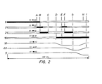
- FIGS. 2 and 3 are the associated flowcharts.
- FIG. 1 shows a control stage 13 of a control winding, the load current of which can be fed to a common derivative 16 via a lower or higher winding tapping 11, 12 and at least two selector contacts 14, 15 and two permanent contacts 9, 10.
- the changeover from the lower to the higher winding tapping or vice versa takes place via a changeover switch 5, the load current passing briefly to a relief circuit 17 which is arranged between the root connection 6 of the changeover switch 5 and the common derivative 16.
- One of each of the two contacts 7, 8 of the changeover switch 5 is connected to the connection of the selector contact 14, 15 to the permanent contact 9, 10.
- the relief circuit 17 consists of a changeover switch 18 and a series thyristor circuit 2 with antiparallel connected thyristors 2a, 2b.
- a switching resistor 4 is connected to the common derivative 16 via a bypass switch 23.
- One changeover contact 20 of the changeover switch 18 is directly connected, the other changeover contact 21 is connected to the root connection 6 of the changeover switch 5 via the switching resistor 4.
- the switching times for the ignition of the thyristors 2a, 2b are offset asymmetrically.
- step tap 11 a switchover from step tap 11 to step tap 12 of control stage 13 of a control winding is described in steps.
- the links - The designations on the side in FIG. 2 correspond to the switches or thyristors and contacts in FIG. 1.
- 11 _ 12 means the switching direction from tap 11 to 12.
- the first of the two fields which relate to the thyristor circuit 2 shows Field the duration of the ignition pulses, the second field the duration of the current flow through the thyristors.
Abstract
Description
Die Erfindung betrifft eine Anordnung bei ei - nem Lastumschalter eines Stufenschalters zum unterbrechungslosen Umschalten der Regelwicklung eines Transformators, wobei-der Laststrom über eine niedere oder höhere Wicklungsanzapfung einer Regelstufe einer Regelwicklung und über eine Verbindung von mindestens zwei Wäh - lerkontakten und zwei Dauerkontakten mit einer gemeinsamen Ableitung führbar ist, und wobei die Umschaltung von der niederen auf die höhere Wicklungsanzapfung oder umgekehrt über einen ersten Umschalter derart erfolgt, daß der Laststrom kurzzeitig auf einen Entlastungskreis übergeht, der zwischen dem Wurzelanschluß dieses ersten Um - schalters und der gemeinsamen Ableitung angeordnet ist, und wobei jeweils einer der beiden Kontakte des ersten Umschalters an die Verbin - dung eines Wählerkontaktes mit einem Dauerkon - takt gelegt ist.The invention relates to an arrangement in a load changeover switch of a tap changer for uninterrupted switching of the control winding of a transformer, the load current via a low or higher winding tap of a control stage of a control winding and via a connection of at least two selector contacts and two permanent contacts with a common one Derivation is feasible, and the changeover from the lower to the higher winding tapping or vice versa takes place via a first changeover switch in such a way that the load current is briefly transferred to a relief circuit which is arranged between the root connection of this first changeover switch and the common discharge line, and whereby one of the two contacts of the first changeover switch is connected to the connection of a selector contact with a permanent contact.
Üblicherweise wird bei Stufentransformatoren die unterbrechungslose Lastumschaltung unter Spannung mit mechanischen Schaltelementen durchgeführt. Die zu schaltende Regelwicklung besitzt Anzapfungen, die mit einem Wähler verbunden sind, welcher sie wahlweise über den Lastumschalter an die gemeinsame Ableitung legt.In the case of step transformers, the uninterrupted load switching is usually carried out under voltage using mechanical switching elements. The control winding to be switched has taps, which are connected to a selector, which can be connected to the common derivative via the diverter switch.
Die Umschaltung erfolgt immer zwischen benachbarten Anzapfungen, also um jeweils eine Stufe. Zu diesem Zweck wird zuerst die gewünschte Anzapfung mit dem Wähler vorgewählt. Danach führt der Lastumschalter, unter zeitweiliger Zwischenschaltung von Überschaltwiderständen, die Umschaltung des Stromes von der gewählten auf die vorgewählte Anzapfung durch. In den bei - den Endstellungen sind die Überschaltwiderstände, da sie durch die Hauptkontakte des Lastumschal - ters überbrückt sind, nicht belastet.Switching always takes place between adjacent taps, i.e. one level at a time. For this purpose, the desired tap with the voter is preselected. The diverter switch then switches the current from the selected to the preselected tap, with intermittent switching resistors. In the two end positions, the switching resistances are not loaded because they are bridged by the main contacts of the diverter switch.
Wähler und Lastumschalter sind üblicherweise im Trafokessel untergebracht, wobei sich der Lastumschalter in einem eigenen Bottich befindet, dessen Ölfüllung von der des Trafos durch Dich - tungen getrennt ist.The selector and diverter switch are usually housed in the transformer tank, the diverter switch being in its own vat, the oil filling of which is separated from that of the transformer by seals.
Von Nachteil ist dabei der beim Umschalten auftretende Abbrand der Kontakte und die Verruß - ung des Öles durch die beim Schalten auftretenden Lichtbögen. Es müssen daher zur Gewährleistung eines einwandfreien Betriebes Kontakte und Öl nach einer bestimmten Schaltzahl gewechselt werden, so daß es durch die damit bedingte Abschaltung des Trafos zu Betriebsunterbrechungen kommt.Disadvantages here are the erosion of the contacts that occurs when switching and the sooting of the oil due to the arcing that occurs during switching. To ensure proper operation, contacts and oil must therefore be changed after a certain number of operations, so that the switch-off of the transformer caused by this leads to interruptions in operation.
Weiters sind Ausführungen bekannt, bei denen die Lastumschaltung mit einer Kombination von mechanischen Schaltelementen und Thyristoren durchgeführt wird. Aus der GB-A-1 1 399 528 ist eine solche Kombination ersichtlich.Furthermore, designs are known in which the load switching is carried out using a combination of mechanical switching elements and thyristors. Such a combination can be seen from GB-A-1 1 399 528.
Die in der GB-A-1 399 528 beschriebene Anordnung besteht aus mindestens zwei Wähler-und zwei Dauerkontakten, einem Überschaltwiderstand sowie einem Entlastungskreis mit zwei anti - parallelgeschalteten Thyristoren, zwei Zünddioden und einem Thyristor-Ansteuerungskontakt.The arrangement described in GB-A-1 399 528 consists of at least two selector contacts and two permanent contacts, a circuit breaker and a relief circuit with two anti-parallel thyristors, two ignition diodes and a thyristor control contact.
Der Wähler besteht aus zwei nicht gleichzeitig bewegten einpoligen Umschaltern, wobei die Um - schaltkontakte des einen Umschalters mit den Umschaltkontakten des anderen Umschalters ver - bunden und an jeweils eine Anzapfung einer Regelstufe einer Regelwicklung gelegt sind.The selector consists of two single-pole changeover switches that are not moved at the same time, the changeover contacts of one changeover switch being connected to the changeover contacts of the other changeover switch and being connected to a control stage of a control winding.
Von den Wurzelanschlüssen der beiden Wäh - ler führt eine leitende Verbindung direkt, die andere über den Überschaltwiderstand zu je einem Wurzelanschluß der beiden Dauerkontakte.One conductive connection leads directly from the root connections of the two selectors, the other to the root connection of the two permanent contacts via the switching resistor.
Über die Wähler- und Dauerkontakte erfolgt, je nach Schaltstellung direkt oder über den Thyri - storkreis, eine Verbindung zu einer gemeinsamen Ableitung.Via the selector and permanent contacts, depending on the switching position, there is a connection to a common derivation, or via the thyristor circuit.
In der Mittelstellung schließen die Dauerkon - takte den Thyristorkreis kurz. Sowohl die Dauerkontakte als auch der Thyristor-Ansteuerungskontakt sind starr mit einer Antriebswelle verbun - den.In the middle position, the permanent contacts short the thyristor circuit. Both the permanent contacts and the thyristor control contact are rigidly connected to a drive shaft.
Beim Einschaltvorgang übernimmt zuerst die Thyristorgruppe den Laststrom. Dann wird diese abgeschaltet und dadurch der Laststrom auf den Strompfad des Überschaltwiderstandes gezwungen. Die Vorwahl der nächsten Regelstufe erfolgt dadurch, daß einer der beiden Wählerkontakte zur gewünschten Anzapfung bewegt wird. Nun schaltet der Thyristorkreis den Laststrom auf diese vorgewählte Anzapfung. Während über einen Wählerkontakt der Laststrom fließt, führt der zweite Wäh - lerkontakt den Ausgleichsstrom.When switching on, the thyristor group first takes over the load current. Then this is switched off and the load current is forced onto the current path of the transition resistor. The next control stage is preselected by moving one of the two selector contacts to the desired tap. Now the thyristor circuit switches the load current to this preselected tap. While the load current flows through one selector contact, the second selector contact carries the equalizing current.
Aus dieser Anordnung ergeben sich mehrere Nachteile. Beim Umschaltvorgang wird die Thyri - storgruppe mit der Summe aus Laststrom und Ausgleichsstrom belastet. In der Endstellung liegen beide Wähler auf einer Anzapfung; daher kann man, bei gleicher Kontaktzahl, nur die Hälfte der Anzapfungen am Wählerumfang unterbringen. Zu - dem sind die Wählerkontakte in den Umschaltvorgang so integriert, daß aus ihrer langsamen Bewegung eine Erhöhung der zeitlichen Belastung der Thyristoren um mindestens eine Größenord - nung resultiert.There are several disadvantages to this arrangement. During the switchover process, the thyristor group is loaded with the sum of the load current and the compensation current. In the end position, both voters are tapped; therefore, with the same number of contacts, only half of the taps can be accommodated on the electorate. In addition, the selector contacts are integrated into the switching process so that their slow movement results in an increase in the time load of the thyristors by at least one order of magnitude.
Eine andere Anordnung zur Lastumschaltung mit mechanischen Schaltelementen und Thyristoren zeigt die DE - PS 2 104 076.Another arrangement for load switching with mechanical switching elements and thyristors is shown in DE -
Auch hier wird der Laststrom über Wicklungsanzapfungen der Regelstufe einer Regelwicklung und über Wähler - und Dauerkontakte einer gemeinsamen Ableitung zugeführt. Statt der üblichen zwei Überschaltwiderstände ist hier jeweils ein Thyristorkreis mit antiparallelgeschalteten Thyri - storen angeordnet. Die beiden Thyristorkreise sind über jeweils einen Trennkontakt mit der gemein - samen Ableitung verbunden.Here, too, the load current is fed to the control stage of a control winding via winding taps and to a common derivation via selector and permanent contacts. Instead of the usual two contact resistors, a thyristor circuit with anti-parallel thyristors is arranged here. The two thyristor circuits are connected to the common lead via a separate contact.
Der Schaltablauf wird durch eine Logikschal - tung gesteuert. Der Ablauf erfolgt derart, daß der Laststrom stets von den Thyristoren geschaltet und, abhängig vom jeweils durchzuführenden Schaltvorgang, entweder anschließend auf den Dauerkontakt kommutiert wird, oder vorher vom Dauerkontakt auf die Thyristoren kommutiert wor - den ist.The switching sequence is controlled by a logic circuit. The sequence is such that the load current is always switched by the thyristors and, depending on the switching process to be carried out, is either subsequently commutated to the permanent contact or has previously been commutated from the permanent contact to the thyristors.
Nachteilig dabei ist der große Aufwand an den zur Steuerung benötigten elektronischen Bauteilen und deren Störanfälligkeit.The disadvantage here is the great expense of the electronic components required for control and their susceptibility to malfunction.
Ein weiterer Nachteil ist die Beeinflussung des Elektronikteils durch die Hochspannung. Zudem besteht die Gefahr, daß die magnetischen Felder der Trafowicklungen Fehlzündungen der Thyristoren auslösen.Another disadvantage is the influence of the high voltage on the electronic part. There is also the risk that the magnetic fields of the transformer windings will trigger misfires of the thyristors.
In der GB - PS 1 007 496 ist eine weitere Anordnung zur Lastumschaltung beschrieben. Hierbei besteht von jeder Anzapfung der Transformator-Regelwicklung eine feste leitende Verbindung zu jeweils einem Paar antiparallelgeschalteter Thyristoren, deren Abgänge mit der gemeinsamen Ableitung verbunden sind.Another arrangement for load switching is described in GB-PS 1 007 496. Each tap of the transformer control winding has a fixed conductive connection to a pair of antiparallel connected thyristors, the outgoers of which are connected to the common derivative.
Über einen Steuerstromkreis des Transformators werden die Thyristoren geschaltet. Die Um - schaltung von einer Stufe auf eine andere wird durchgeführt, indem das gewählte Thyristorpaar vom leitenden in den nichtleitenden, und das vorgewählte vom nichtleitenden in den leitenden Schaltzustand gesetzt wird.The thyristors are switched via a control circuit of the transformer. Switching from one stage to another is carried out by switching the selected thyristor pair from the conductive to the non-conductive, and the preselected from the non-conductive to the conductive switching state.
Nachteilig bei dieser Anordnung ist der hohe technische Aufwand und die Störanfälligkeit der zur Steuerung nötigen elektronischen Bauteile.A disadvantage of this arrangement is the high technical complexity and the susceptibility to malfunction of the electronic components required for control.
In der DE-AS 23 27 610 ist eine Ausführung beschrieben, die aus zwei Lastzweigen besteht, welche jeweils eine Anzapfung der Regelwicklung mit einer gemeinsamen Ableitung verbinden. In jedem Lastzweig liegen ein Wähler- und ein Trennkontakt sowie eine Parallelschaltung, bestehend aus einem Thyristor und einem Dauerkontakt, in Serie. Die Thyristoren sind entgegengesetzt gepolt.DE-AS 23 27 610 describes an embodiment which consists of two load branches, each of which connects a tap of the control winding with a common derivative. A selector and an isolating contact as well as a parallel connection, consisting of a thyristor and a permanent contact, are in series in each load branch. The thyristors are polarized in opposite directions.
Zwischen den beiden Lastzweigen ist ein Stromzweig angeordnet, der über einen Umschalter jeweils einem der beiden Lastzweige parallelge - schaltet werden kann. Dieser Stromzweig besteht aus zwei antiparallelgeschalteten Dioden, denen der Eingang eines Spannungserfassungs- und Zündgerätes parallel liegt.A current branch is arranged between the two load branches, which can be connected in parallel to one of the two load branches via a changeover switch. This current branch consists of two antiparallel connected diodes, the input of a voltage detection and ignition device is in parallel.
Bei dieser Ausführung sind zu Beginn der Umschaltung von einer ersten auf eine zweite An - zapfung der der ersten Anzapfung bzw. dem ersten Lastzweig zugeordnete Trennkontakt und Dauerkontakt geschlossen. Der zusätzliche Stromzweig ist über den Synchron - Umschalter diesem Last - zweig parallelgeschaltet.In this embodiment, at the start of the switchover from a first to a second tap, the isolating contact and the permanent contact assigned to the first tap or the first load branch are closed. The additional current branch is connected in parallel to this load branch via the synchronous switch.
Durch Öffnen des Dauerkontaktes im ersten Lastzweig wird der Laststrom auf den zusätzlichen Stromzweig kommutiert. Nach dem Schließen des Trennkontaktes im zweiten Lastzweig wird der er - ste Thyristor gezündet und gleichzeitig der Umschaltimpuls für den Synchron - Umschalter abge - setzt. Der Synchron - Umschalter hebt vom ersten Umschaltkontakt ab, der Strom kommutiert auf den ersten Thyristor. Durch Sperrung des ersten und Zündung des zweiten Thyristors im zweiten Lastzweig wechselt der Strom von der ersten auf die zweite Anzapfung und somit über den zweiten Wählerkontakt auf den zweiten Thyristor.By opening the permanent contact in the first load branch, the load current is commutated to the additional current branch. After the isolating contact in the second load branch is closed, the first thyristor is ignited and the changeover pulse for the synchronous changeover switch is released at the same time. The synchronous changeover switch lifts from the first changeover contact, the current commutates to the first thyristor. By blocking the first and igniting the second thyristor in the second load branch, the current changes from the first to the second tap and thus via the second selector contact to the second thyristor.
Inzwischen ist der Synchron - Umschalter am zweiten Umschaltkontakt angelangt, der Laststrom wird vom zusätzlichen Stromzweig übernommen. Mit dem Öffnen des Trennkontaktes im ersten und dem Schließen des Dauerkontaktes im zweiten Lastzweig ist der Umschaltvorgang beendet.In the meantime the synchronous changeover switch has reached the second changeover contact, the load current is taken over by the additional current branch. The switching process ends when the isolating contact in the first and the permanent contact in the second load branch is closed.
Diese Ausführung hat den Nachteil, daß die Umschaltung nicht für alle Betriebsfälle und Schaltzeitpunkte gewährleistet werden kann, da sie im Stromnulldurchgang erfolgen soll, welcher erst durch komplizierte und störanfällige elektronische Geräte zu messen ist.This embodiment has the disadvantage that the switchover cannot be guaranteed for all operating cases and switching times, since it is to take place at zero current, which can only be measured by complicated and fault-prone electronic devices.
Auch in der US-A-3 3 662 253 ist eine Lastumschaltung beschrieben, wobei zwischen einer gemeinsamen Ableitung und zwei Wählerkontakten zwei Vakuumschalter angeordnet sind. Weiters ist ein Entlastungskreis vorgesehen, welcher zwischen der gemeinsamen Ableitung sowie - durch Verwendung eines Umschalters - jeweils einem Wählerkontakt liegt und so ausgeführt ist, daß er zu jeweils einem der beiden Vakuumschaltern paral - lelgeschaltet werden kann.A load switchover is also described in US Pat. No. 3,662,253, two vacuum switches being arranged between a common lead and two selector contacts. Furthermore, a relief circuit is provided, which lies between the common derivation and - by using a changeover switch - one selector contact each and is designed so that it can be connected in parallel to one of the two vacuum switches.
Der Entlastungskreis enthält eine Serienschal - tung eines strombegrenzenden Widerstandes mit einem Halbleiterschalter. Für diesen Halbleiterschalter ist ein Bypasskreis mit großer Impedanz vorgesehen, um auftretende Stromanstiege zu begrenzen. Der Kreis des Bypasskreises ist mit der Primärwicklung eines Stromwandlers gekoppelt, dessen Sekundärwicklung einem Gittersteuergerät zugeführt ist. Das Gittersteuergerät beinhaltet Steuerglieder, welche den sekundären Stromanstieg des im Kreis des Bypasskreises eingebrach - ten Stromwandlers ausnützen.The relief circuit contains a series connection of a current limiting resistor with a semiconductor switch. A bypass circuit with high impedance is provided for this semiconductor switch in order to limit occurring current increases. The circuit of the bypass circuit is coupled to the primary winding of a current transformer, the secondary winding of which is fed to a grid control device. The grid control unit contains control elements which use the secondary current rise of the current transformer integrated in the bypass circuit.
Das Umschalten der Anzapfungen unter Last erfolgt, unter Zwischenschaltung des Entlastungs - kreises, während der voneinander abhängigen Einschalt - bzw. Ausschaltbewegungen der Vaku - umschalter.The taps are switched under load, with the relief circuit interposed, during the interdependent switch-on and switch-off movements of the vacuum switches.
In dieser US-A-3 662 253 wird auch ein aufwendigeres System zum Umschalten der An - zapfungen von Regeltransformatoren vorgeschlagen, bei welchem wiederum zwei Vakuumschalter zwischen der gemeinsamen Ableitung und den Wählerkontakten liegen. Auch hier ist ein Entlastungskreis zwischen der gemeinsamen Ableitung und einem Umschalter derart angeordnet, daß der Entlastungskreis parallel zu jeweils einem der bei - den Vakuumschalter gelegt werden kann.This US-A-3 662 253 also proposes a more complex system for switching the taps of regulating transformers, in which in turn two vacuum switches are located between the common discharge line and the selector contacts. There is also an outlet here circuit between the common discharge line and a changeover switch arranged in such a way that the relief circuit can be placed parallel to one of the two vacuum switches.
Der Entlastungskreis besteht aus einer Serienschaltung eines Halbleiterschalters mit einem ohmschen Widerstand; diese Serienschaltung ist einem Halbleiterschalter parallelgeschaltet. Zur Verhinderung eines Spannungsanstieges während der Umschaltvorgänge ist, parallel zum Halbleiterschalter der Serienschaltung, ein Spannungsbegrenzungskreis vorgesehen.The relief circuit consists of a series connection of a semiconductor switch with an ohmic resistor; this series circuit is connected in parallel to a semiconductor switch. To prevent a voltage rise during the switching processes, a voltage limiting circuit is provided in parallel to the semiconductor switch of the series circuit.
Die Verbindungsleitungen zwischen den beiden Vakuumschaltern und der gemeinsamen Ableitung, sowie die Verbindungsleitung zwischen dem Spannungsbegrenzungskreis und der gemeinsamen Ableitung sind jeweils mit der Primärwicklung eines zugeordneten von drei Stromwandlern gekoppelt. Die Sekundärwicklungen dieser Strom - wandler sind mit jeweils einem zugeordneten von drei Gittersteuergeräten verbunden, denen die zeitgerechte Zündung der Halbleiterschalter des Entlastungskreises obliegt. Durch entsprechende Zündeinstellung wird erreicht, daß während des Öffnens und Schließens der Vakuumschalter der Laststrom über die Halbleiterschalter fließt, so daß ein Lichtbogen verhindert wird.The connecting lines between the two vacuum switches and the common derivative, as well as the connecting line between the voltage limiting circuit and the common derivative, are each coupled to the primary winding of an associated one of three current transformers. The secondary windings of these current transformers are each connected to an assigned one of three grid control units, which are responsible for the timely ignition of the semiconductor switches of the relief circuit. A corresponding ignition setting ensures that the load current flows through the semiconductor switches during the opening and closing of the vacuum switches, so that an arc is prevented.
Der Nachteil der in der US-A-3 662 253 vorgeschlagenen Schaltungsanordnungen liegt im umfangreichen und störungsanfälligen technischen Aufwand.The disadvantage of the circuit arrangements proposed in US Pat. No. 3,662,253 lies in the extensive and fault-prone technical outlay.
Die Aufgabe der Erfindung besteht daher darin, eine Anordnung bei einem Lastumschalter eines Stufenschalters zum unterbrechungslosen Um - schalten der Regelwicklung eines Transformators der eingangs genannten Art zu schaffen, welche die Nachteile der bekannten Anordnungen vermeidet und die Spannungs - und Strombelastung der Thyristoren beim Umschaltvorgang auf einem Minimum hält.The object of the invention is therefore to provide an arrangement in a load changeover switch of a tap changer for the uninterrupted switching of the control winding of a transformer of the type mentioned at the outset, which avoids the disadvantages of the known arrangements and the voltage and current loading of the thyristors during the switching process on one Minimum holds.
Die Aufgabe wird durch die Erfindung gelöst. Diese ist dadurch gekennzeichnet, daß der Entlastungskreis aus einem zweiten Umschalter und ei - nem dazu in Serie liegenden Thyristorkreis mit antiparallelgeschalteten Thyristoren besteht, und daß ein Überschaltwiderstand über einen Überbrückungsschalter mit der gemeinsamen Ableitung verbunden ist, und daß der eine Umschaltkontakt des zweiten Umschalters direkt und der andere Umschaltkontakt dieses zweiten Umschalters über den Überschaltwiderstand mit dem Wurzelanschluß des ersten Umschalters verbunden ist.The object is achieved by the invention. This is characterized in that the relief circuit consists of a second changeover switch and a thyristor circuit in series with antiparallel connected thyristors, and that a tripping resistor is connected to the common derivative via a bypass switch, and that the one changeover contact of the second changeover switch is direct and the other changeover contact of this second changeover switch is connected to the root connection of the first changeover switch via the transition resistor.
Durch diese Anordnung wird der Bauteilauf - wand, um ein lichtbogenfreies Schalten von einer Regelstufe zur anderen zu erreichen, relativ gering gehalten. Selbstverständlich wird damit auch ein Kontaktabbrand an den Dauerkontakten verhindert. In den Endstellungen erfolgt keine Belastung der Thyristoren, da sie durch den jeweiligen parallel angeordneten Dauerkontakt überbrückt sind. Eine Belastung der Thyristoren durch Kurzschlußströme ist ebenfalls vermieden.With this arrangement, the component expenditure in order to achieve an arc-free switching from one control stage to another is kept relatively low. Of course, this also prevents contact erosion on the permanent contacts. In the end positions, there is no load on the thyristors, since they are bridged by the respective permanent contact arranged in parallel. A load on the thyristors by short-circuit currents is also avoided.
Unter Zugrundelegung einer Überschaltzeit von 120 ms können die beim bekannten Lastumschalter verwendeten mechanischen Schaltelemente sowie die Überschaltwiderstände verwendet werden.On the basis of a switchover time of 120 ms, the mechanical switching elements used in the known diverter switch and the switchover resistances can be used.
Weiters ist vorteilhaft, daß nur eine Zündvorrichtung erforderlich ist, die im Laufe eines Umschaltvorganges zwei Mal betätigt wird.It is also advantageous that only one ignition device is required, which is actuated twice in the course of a switching process.
Nach einer Weiterbildung sind die beiden Dauerkontakte als ein weiterer Umschaltkontakt sind.According to a further development, the two permanent contacts are a further changeover contact.
Dadurch werden Schaltkontakte eingespart, und außerdem wird auf einfache Art die Ausführung als Lastwähler erreicht.This saves switching contacts, and in addition, the design as a load selector is achieved in a simple manner.
Die nähere Erläuterung der Erfindung erfolgt unter Zuhilfenahme von Zeichnungen, wobei Fig. 1 den erfindungsgemäßen Lastumschalter darstellt, und Fig. 2 und 3 die zugehörigen Ablaufdiagram - me sind.The invention is explained in more detail with the aid of drawings, in which FIG. 1 represents the diverter switch according to the invention, and FIGS. 2 and 3 are the associated flowcharts.
Fig. 1 zeigt eine Regelstufe 13 einer Regel - wicklung, deren Laststrom über eine niedere oder höhere Wicklungsanzapfung 11, 12 und über mindestens zwei Wählerkontakte 14, 15 und zwei Dauerkontakte 9, 10 einer gemeinsamen Ableitung 16 zuführbar ist. Die Umschaltung von der niederen auf die höhere Wicklungsanzapfung oder umgekehrt erfolgt über einen Umschalter 5, wobei der Laststrom kurzzeitig auf einen Entlastungskreis 17 übergeht, der zwischen dem Wurzelanschluß 6 des Umschalters 5 und der gemeinsamen Ableitung 16 angeordnet ist. Von den beiden Kontakten 7, 8 des Umschalters 5 ist jeweils einer an die Verbindung des Wählerkontakts 14, 15 mit dem Dauerkontakt 9, 10 gelegt.1 shows a
Der Entlastungskreis 17 besteht aus einem Umschalter 18 und einem dazu in Serie liegenden Thyristorkreis 2 mit antiparallelgeschalteten Thyri - storen 2a, 2b. Ein Überschaltwiderstand 4 ist über einen Überbrückungsschalter 23 mit der gemeinsamen Ableitung 16 verbunden. Der eine Umschaltkontakt 20 des Umschalters 18 ist direkt, der andere Umschaltkontakt 21 über den Überschaltwiderstand 4 mit dem Wurzelanschluß 6 des Um - schalters 5 verbunden.The
Wie aus den Ablaufdiagrammen Fig. 2 und 3 ersichtlich, sind die Schaltzeiten für die Zündung der Thyristoren 2a, 2b asymmetrisch versetzt.2 and 3, the switching times for the ignition of the
Diese Asymmetrie in beiden Schaltrichtungen, sowie die Endkontakt - Umschaltung des Umschalters 5 ist mechanisch herzustellen.This asymmetry in both switching directions, as well as the end contact changeover of the
Im folgenden wird an Hand der Fig. 1 und 2 eine Umschaltung von der Stufenanzapfung 11 auf die Stufenanzapfung 12 der Regelstufe 13 einer Regelwicklung in Schritten beschrieben. Die links - seitigen Bezeichnungen in Fig. 2 entsprechen den Schaltern bzw. Thyristoren und Kontakten in Fig. 1. Außerdem bedeutet 11 _ 12 die Schaltrichtung von Anzapfung 11 auf 12. Von den zwei Feldern, wel - che sich auf den Thyristorkreis 2 beziehen, zeigt das erste Feld die Dauer der Zündimpulse, das zweite Feld die Dauer des Stromflusses durch die Thyristoren.1 and 2, a switchover from
-
A Wählerkontakte 14, 15 und Dauerkontakt 9 geschlossen; Umschalter 5 verbindet Kontakt 7 über Wurzelanschluß 6 mit Entlastungskreis 17; Entlastungskreis 17 befindet sich im nichtleitenden Schaltzustand; Umschalter 18 verbindet Kontakt 20 mit Wurzelanschluß 19; Thyristorkreis 2 im nichtleitenden Schaltzustand; Überbrükkungsschalter 23 geschlossen; Laststrom fließt über Wicklungsanzapfung 11 der Regelstufe 13 der Regelwicklung, sowie über Wähler- 14 und Dauerkontakt 9 zur gemeinsamen Ableitung 16. Thyristorkreis 2 wird gezündet.A
Selector contacts permanent contact 9 closed;Switch 5 connects contact 7 via root connection 6 withrelief circuit 17;Relief circuit 17 is in the non-conductive switching state;Changeover switch 18 connectscontact 20 withroot connection 19;Thyristor circuit 2 in the non-conductive switching state; Bridgingswitch 23 closed; Load current flows via winding tapping 11 ofcontrol stage 13 of the control winding, as well as viaselector 14 andpermanent contact 9 forcommon derivation 16.Thyristor circuit 2 is ignited. -
B Dauerkontakt 9 öffnet, Thyristorkreis 2 übernimmt Laststrom.
B Permanent contact 9 opens,thyristor circuit 2 takes over load current. -
C Thyristorkreis 2 wird nicht mehr gezündet und führt Strom nur mehr bis zum näch - sten Nulldurchgang; danach fließt Laststrom über Überschaltwiderstand 4 und Überbrückungsschalter 23.
C Thyristor circuit 2 is no longer ignited and only carries current until the next zero crossing; after that, load current flows through contact resistance 4 andbypass switch 23. -
D Umschalter 18 öffnet, Dauerkontakt 10 schließt; Laststrom, vermindert um den Ausgleichsstrom, fließt über Wicklungsanzapfung 12, Wählerkontakt 15 und Dauerkontakt 10 zur gemeinsamen Ablei - tung 16; Ausgleichsstrom fließt über Überschaltwiderstand 4 und Kontakt 23.
D switch 18 opens,permanent contact 10 closes; Load current, reduced by the compensating current, flows via winding tapping 12,selector contact 15 andpermanent contact 10 to thecommon lead 16; Compensating current flows through contact resistance 4 andcontact 23. -
E Umschalter 18 verbindet Wurzelanschluß 19 mit Kontakt 21, Thyristorkreis 2 wird gezündet.
E changeover switch 18 connectsroot connection 19 withcontact 21,thyristor circuit 2 is ignited. -
F Überbrückungsschalter 23 öffnet; Ausgleichsstrom fließt über Thyristorkreis 2.
F bypass switch 23 opens; Compensating current flows throughthyristor circuit 2. -
G Thyristorkreis 2 wird nicht mehr gezündet und führt den Ausgleichsstrom nur mehr bis zum nächsten Nulldurchgang; danach fließt Laststrom über Wicklungsanzapfung 12, Wählerkontakt 15 und Dauerkontakt 10 zur gemeinsamen Ableitung 16.
G Thyristor circuit 2 is no longer ignited and only leads the compensating current until the next zero crossing; then load current flows via winding tapping 12,selector contact 15 andpermanent contact 10 to thecommon derivation 16. -
H Umschalter 5 schaltet Wurzelanschluß 6 von Kontakt 7 auf Kontakt 8.
I Umschalter 18 schaltet von Kontakt 21 auf Kontakt 20; Überbrückungsschalter 23 schließt; damit ist der Entlastungskreis für die nächste Stufenumschaltung bereit.H Switch 5 switches root connection 6 from contact 7 to contact 8.
I switch 18 switches fromcontact 21 to contact 20;Bypass switch 23 closes; the relief circuit is now ready for the next level changeover.
Für den Entlastungskreis nach Fig. 1 gelten nachfolgende Zusammenhänge. Strom - Belastungsdauer des Thyristorkreises 2: tL ... 15 + 20 ms
- Spannungsbelastung des Thyristorkreises 2: UTH = IL x Rü
Belastung des Thyristorkreises 2 durch Ausgleichsstrom:
- Ausgleichsstrom - Belastungsdauer: tA ... 5 + 15 ms
- Voltage load of the thyristor circuit 2: U TH = I L x Rü
- Load of
thyristor circuit 2 by compensating current: - Balance current - load duration: t A ... 5 + 15 ms
Hierbei sind:
- tL Strom - Belastungsdauer
- IL Laststrom
- IA Ausgleichsstrom
- UTH Spannung am Thyristor
- EST Stufenspannung
- Rü Überschaltwiderstand
- tA Ausgleichsstrom - Belastungsdauer
- t L current - load duration
- I L load current
- I A equalizing current
- U TH voltage at the thyristor
- E ST step voltage
- Rü overvoltage resistance
- t A equalizing current - load duration
An Hand der Fig. 1 und 3 wird eine andere Vari - ante der Umschaltung von der Stufenanzapfung 11 auf die Stufenanzapfung 12 der Regelstufe 13 der Regelwicklung beschrieben.Another variant of the changeover from the tap tapping 11 to the
Die Schritte A bis C sind äquivalent mit der vorigen Beschreibung des Umschaltvorganges. Die weiteren Schritte sind nachfolgend angeführt.
D Umschalter 18schaltet Wurzelanschluß 19von Kontakt 20auf Kontakt 21. Thyristor -kreis 2 wird gezündet.E Überbrückungsschalter 23 öffnet;Thyristorkreis 2 übernimmt den Laststrom.F Dauerkontakt 10 schließt; Laststrom, vermindert um den Ausgleichsstrom, fließt über Stufenanzapfung 12,Wählerkontakt 15 und Dauerkontakt 10 zur gemeinsamen Ableitung 16;Thyristorkreis 2 führt den Ausgleichsstrom.G Thyristorkreis 2 wird nicht mehr gezündet und führt den Ausgleichsstrom nur mehr bis zum nächsten Nulldurchgang.H Umschalter 5 schaltet Wurzelanschluß 6 von Kontakt 7auf Kontakt 8. I Umschalter 18schaltet von Kontakt 21auf Kontakt 20;Überbrückungsschalter 23 schließt; damit ist der Entlastungskreis für die nächste Stufenumschaltung bereit.
-
D Changeover switch 18switches root connection 19 fromcontact 20 to contact 21.Thyristor circuit 2 is ignited. -
E bypass switch 23 opens;Thyristor circuit 2 takes over the load current. - F
permanent contact 10 closes; Load current, reduced by the compensating current, flows via tap tapping 12,selector contact 15 andpermanent contact 10 to thecommon derivative 16;Thyristor circuit 2 carries the equalizing current. -
G Thyristor circuit 2 is no longer ignited and only leads the compensating current to the next zero crossing. -
H switch 5 switches root connection 6 from contact 7 to contact 8. I switch 18 switches fromcontact 21 to contact 20;Bypass switch 23 closes; the relief circuit is now ready for the next level changeover.
Claims (2)
Applications Claiming Priority (3)
| Application Number | Priority Date | Filing Date | Title |
|---|---|---|---|
| AT0160187A AT400496B (en) | 1987-06-25 | 1987-06-25 | THYRISTOR LOAD SWITCH |
| AT1601/87 | 1987-06-25 | ||
| PCT/AT1988/000045 WO1988010502A1 (en) | 1987-06-25 | 1988-06-14 | Thyristor on-load change-over switch |
Publications (3)
| Publication Number | Publication Date |
|---|---|
| EP0375687A1 EP0375687A1 (en) | 1990-07-04 |
| EP0375687B1 true EP0375687B1 (en) | 1993-05-12 |
| EP0375687B2 EP0375687B2 (en) | 1997-04-02 |
Family
ID=3516943
Family Applications (1)
| Application Number | Title | Priority Date | Filing Date |
|---|---|---|---|
| EP88905150A Expired - Lifetime EP0375687B2 (en) | 1987-06-25 | 1988-06-14 | Thyristor on-load change-over switch |
Country Status (9)
| Country | Link |
|---|---|
| US (1) | US5006784A (en) |
| EP (1) | EP0375687B2 (en) |
| JP (1) | JP2662434B2 (en) |
| AT (2) | AT400496B (en) |
| BG (1) | BG50510A3 (en) |
| DE (1) | DE3881052D1 (en) |
| HU (1) | HU203425B (en) |
| SU (1) | SU1739862A3 (en) |
| WO (1) | WO1988010502A1 (en) |
Cited By (1)
| Publication number | Priority date | Publication date | Assignee | Title |
|---|---|---|---|---|
| DE10028295C1 (en) * | 2000-06-07 | 2001-08-16 | Reinhausen Maschf Scheubeck | Tap changer |
Families Citing this family (32)
| Publication number | Priority date | Publication date | Assignee | Title |
|---|---|---|---|---|
| DE3935866A1 (en) * | 1989-10-27 | 1991-05-02 | Reinhausen Maschf Scheubeck | ARRANGEMENT AND METHOD FOR LOAD SWITCHING FOR LOAD SWITCHES OF TAPE SWITCHES |
| US5227713A (en) * | 1991-08-08 | 1993-07-13 | Electric Power Research Institute | Vernier control system for subsynchronous resonance mitigation |
| US5408171A (en) * | 1991-10-21 | 1995-04-18 | Electric Power Research Institute, Inc. | Combined solid-state and mechanically-switched transformer tap-changer |
| US5461300A (en) * | 1993-03-30 | 1995-10-24 | Electric Power Research Institute, Inc. | Phase angle regulating transformer with a single core per phase |
| DE19518272C1 (en) * | 1995-05-18 | 1996-10-24 | Reinhausen Maschf Scheubeck | Tap-switch for transformers |
| US5786684A (en) * | 1996-09-16 | 1998-07-28 | Abb Power T&D Company, Inc. | Apparatus and methods for minimizing over voltage in a voltage regulator |
| AT3152U3 (en) * | 1999-02-16 | 2000-12-27 | Elin Oltc Gmbh Stufenschalter | CIRCUIT ARRANGEMENT FOR A LOAD SWITCH |
| DE10102310C1 (en) * | 2001-01-18 | 2002-06-20 | Reinhausen Maschf Scheubeck | Thyristor stepping switch for stepping transformer has hybrid construction with mechanical stepping switch and thyristor load switching device in separate housing |
| US6559562B1 (en) | 2001-12-14 | 2003-05-06 | Ssi Power, Llc | Voltage sag and over-voltage compensation device with pulse width modulated autotransformer |
| US8207716B2 (en) * | 2004-10-14 | 2012-06-26 | Utility Systems Technologies, Inc. | Useful improvements in the art of 3-phase electronic tap changer commutation device |
| US7737667B2 (en) * | 2004-10-14 | 2010-06-15 | Utility Systems Technologies, Inc. | 3-phase electronic tap changer commutation and device |
| US7595614B2 (en) * | 2007-12-07 | 2009-09-29 | Pennsylvania Transformer Technology, Inc. | Load tap changer |
| DE102008064485A1 (en) * | 2008-12-22 | 2010-06-24 | Siemens Aktiengesellschaft | Tap changer for medium-low voltage transformers |
| DE102009017197A1 (en) | 2009-04-09 | 2010-10-14 | Maschinenfabrik Reinhausen Gmbh | Tap-changer with semiconductor switching elements |
| DE102010008973B4 (en) * | 2010-02-24 | 2015-11-05 | Maschinenfabrik Reinhausen Gmbh | Step switch of the hybrid type with semiconductor switching elements |
| UA112302C2 (en) * | 2010-12-17 | 2016-08-25 | Машіненфабрік Райнхаузен Гмбх | STEP SWITCH |
| DE102012107436A1 (en) * | 2012-08-02 | 2014-02-06 | Maschinenfabrik Reinhausen Gmbh | step switch |
| CN103166161A (en) * | 2013-04-15 | 2013-06-19 | 都匀供电局 | Method and device for adjusting output impedance of ice melting reactor |
| RU2539399C1 (en) * | 2013-07-23 | 2015-01-20 | Федеральное государственное бюджетное образовательное учреждение высшего профессионального образования "Нижегородский государственный технический университет им. Р.Е. Алексеева", НГТУ | Transformer winding taps switching unit |
| US9400512B2 (en) * | 2013-12-17 | 2016-07-26 | General Electric Company | System and method for operating an on load tap changer for regulating voltage on an electric power system |
| US9570252B2 (en) | 2014-01-27 | 2017-02-14 | General Electric Company | System and method for operating an on-load tap changer |
| US9557754B2 (en) | 2014-04-22 | 2017-01-31 | General Electric Company | Load tap changer |
| US10147562B2 (en) * | 2014-11-25 | 2018-12-04 | Hai Wang | On-load voltage regulation tap switch for transformer and switch control method |
| DE102015102727A1 (en) * | 2015-02-25 | 2016-08-25 | Maschinenfabrik Reinhausen Gmbh | Method for changing the active number of turns of a control winding in an electrical system and electrical system with a control winding |
| DE102015106178A1 (en) * | 2015-04-22 | 2016-10-27 | Maschinenfabrik Reinhausen Gmbh | OLTC |
| RU2613679C2 (en) * | 2015-08-19 | 2017-03-21 | Борис Алексеевич Аржанников | Device for regulating voltage and method for its control |
| US10048709B2 (en) | 2016-09-19 | 2018-08-14 | General Electric Company | System and method for regulation of voltage on an electric power system |
| CN113066685B (en) * | 2021-02-08 | 2022-05-20 | 广东电网有限责任公司广州供电局 | Passive triggering contact device of power electronic tap switch |
| DE102020123455A1 (en) | 2020-09-09 | 2022-03-10 | Maschinenfabrik Reinhausen Gmbh | LOAD CONTROLLER AND METHOD OF OPERATING A LOAD CONTROLLER |
| CN112447383B (en) * | 2020-10-22 | 2022-11-25 | 中国电力科学研究院有限公司 | Transition circuit for switching non-multiplexing power electronic on-load tap-changer |
| CN113035603B (en) * | 2021-02-08 | 2022-06-14 | 南方电网科学研究院有限责任公司 | Special-shaped contact device of passive triggering power electronic tap switch |
| RU2754350C1 (en) * | 2021-03-12 | 2021-09-01 | федеральное государственное бюджетное образовательное учреждение высшего образования "Национальный исследовательский университет "МЭИ" (ФГБОУ ВО "НИУ "МЭИ") | Power transformer protection device |
Family Cites Families (21)
| Publication number | Priority date | Publication date | Assignee | Title |
|---|---|---|---|---|
| GB1007496A (en) * | 1962-11-21 | 1965-10-13 | Electric Construction Co | Improvements relating to transformer tap-changing |
| DD40772A1 (en) † | 1964-03-18 | 1965-08-25 | Diverter switch for transformers and reactors | |
| DE1810273B2 (en) * | 1966-04-16 | 1972-04-20 | Maschinenfabnk Reinhausen Gebruder Scheubeck KG, 8400 Regensburg | ARRANGEMENT FOR CHANGING THE LOAD IN STEPPED TRANSFORMERS WITH ANTI-PARALLELLY SWITCHED THYRISTORS |
| DE1638555B2 (en) † | 1967-03-03 | 1972-01-05 | Siemens AG, 1000 Berlin u. 8000 München | ARRANGEMENT AND PROCEDURE FOR LOAD SWITCHING IN STEP TRANSFORMERS |
| AT303208B (en) * | 1968-07-25 | 1972-11-10 | Elin Union Ag | Circuit arrangement for power switching or load switching or load switching with at least one controllable valve |
| DD72826A1 (en) † | 1969-02-12 | 1970-05-05 | Diverter switch for transformers and reactors | |
| FR2044094A5 (en) * | 1969-05-08 | 1971-02-19 | Comp Generale Electricite | |
| JPS507727B1 (en) * | 1969-11-04 | 1975-03-28 | ||
| DE2125471A1 (en) * | 1971-05-22 | 1972-12-07 | Transformatoren Union Ag | Arrangement and procedure for uninterrupted load switching in step transformers |
| DE2207367C2 (en) * | 1972-02-17 | 1974-02-28 | Reinhausen Maschf Scheubeck | Arrangement to prevent step short circuits in diverter switches of step transformers with anti-parallel connected thyristors |
| DE2210049A1 (en) † | 1972-03-02 | 1973-09-06 | Transformatoren Union Ag | ARRANGEMENT AND PROCEDURE FOR UNINTERRUPTED LOAD SWITCHING IN STEPPED TRANSFORMERS |
| GB1399528A (en) * | 1972-06-20 | 1975-07-02 | Krasov A I | Electrical onload tap changing systems |
| DE2327610C3 (en) * | 1973-05-30 | 1979-01-11 | Maschinenfabrik Reinhausen Gebrueder Scheubeck Gmbh & Co Kg, 8400 Regensburg | Diverter switch for step switches of regulating transformers |
| US4081741A (en) * | 1975-10-29 | 1978-03-28 | Asea Aktiebolag | On-load tap changer |
| US4301489A (en) * | 1979-12-19 | 1981-11-17 | Siemens-Allis, Inc. | Arcless tap changer utilizing static switching |
| US4363060A (en) * | 1979-12-19 | 1982-12-07 | Siemens-Allis, Inc. | Arcless tap changer for voltage regulator |
| DE3223892A1 (en) * | 1982-06-26 | 1983-12-29 | Maschinenfabrik Reinhausen Gebrüder Scheubeck GmbH & Co KG, 8400 Regensburg | ARRANGEMENT FOR LOAD SWITCHING OF STEPPING TRANSFORMERS WITH ANTIPARALLY SWITCHED THYRISTORS |
| JPS59125418A (en) * | 1983-01-07 | 1984-07-19 | Mitsubishi Electric Corp | On-load tap changer |
| DE3304851A1 (en) * | 1983-02-12 | 1984-08-16 | Reinhausen Maschf Scheubeck | SWITCHING ARRANGEMENT FOR LOAD SWITCHES FROM TAPE SWITCHES FOR TAPE TRANSFORMERS |
| SE436529B (en) * | 1983-05-10 | 1984-12-17 | Asea Ab | Tap changers |
| US4622513A (en) * | 1984-09-28 | 1986-11-11 | Siemens Energy & Automation, Inc. | Gating of the thyristors in an arcless tap changing regulator |
-
1987
- 1987-06-25 AT AT0160187A patent/AT400496B/en not_active IP Right Cessation
-
1988
- 1988-06-14 US US07/458,735 patent/US5006784A/en not_active Expired - Fee Related
- 1988-06-14 HU HU883753A patent/HU203425B/en not_active IP Right Cessation
- 1988-06-14 AT AT88905150T patent/ATE89433T1/en not_active IP Right Cessation
- 1988-06-14 EP EP88905150A patent/EP0375687B2/en not_active Expired - Lifetime
- 1988-06-14 DE DE8888905150T patent/DE3881052D1/en not_active Expired - Fee Related
- 1988-06-14 JP JP63504985A patent/JP2662434B2/en not_active Expired - Lifetime
- 1988-06-14 WO PCT/AT1988/000045 patent/WO1988010502A1/en active IP Right Grant
-
1989
- 1989-12-11 BG BG90623A patent/BG50510A3/en unknown
- 1989-12-22 SU SU894742765A patent/SU1739862A3/en active
Cited By (1)
| Publication number | Priority date | Publication date | Assignee | Title |
|---|---|---|---|---|
| DE10028295C1 (en) * | 2000-06-07 | 2001-08-16 | Reinhausen Maschf Scheubeck | Tap changer |
Also Published As
| Publication number | Publication date |
|---|---|
| ATE89433T1 (en) | 1993-05-15 |
| WO1988010502A1 (en) | 1988-12-29 |
| EP0375687A1 (en) | 1990-07-04 |
| DE3881052D1 (en) | 1993-06-17 |
| BG50510A3 (en) | 1992-08-14 |
| AT400496B (en) | 1996-01-25 |
| HU203425B (en) | 1991-07-29 |
| JP2662434B2 (en) | 1997-10-15 |
| ATA160187A (en) | 1991-12-15 |
| JPH03500224A (en) | 1991-01-17 |
| SU1739862A3 (en) | 1992-06-07 |
| HUT52270A (en) | 1990-06-28 |
| EP0375687B2 (en) | 1997-04-02 |
| US5006784A (en) | 1991-04-09 |
Similar Documents
| Publication | Publication Date | Title |
|---|---|---|
| EP0375687B1 (en) | Thyristor on-load change-over switch | |
| DE102010008973B4 (en) | Step switch of the hybrid type with semiconductor switching elements | |
| DE102010007535B4 (en) | Tap-changer with freewheeling element | |
| EP3286774B1 (en) | On-load tap changer, a method of operating an on-load tap changer and electric system with an on-load tap changer | |
| DE102010019949A1 (en) | OLTC | |
| EP3050067B1 (en) | Tap changer | |
| WO2012062408A1 (en) | On-load tap changer | |
| WO2020030445A1 (en) | On-load tap changer for switching without any interruption between winding taps of a tap-changing transformer and tap-changing transformer | |
| EP0124904B1 (en) | Tap changing switch | |
| AT406988B (en) | CIRCUIT ARRANGEMENT FOR A LOAD SWITCH | |
| DE19518272C1 (en) | Tap-switch for transformers | |
| DE2321369A1 (en) | LOAD SELECTOR FOR TAP-SWITCHES OF TRANSFORMERS AND REACTORS | |
| DE102014106997A1 (en) | Switching arrangement for a tapped transformer and method for operating such a switching arrangement | |
| DE2757425C2 (en) | Diverter switch for transformers | |
| DE467560C (en) | Switching device for switching the taps of a step transformer during normal, uninterrupted operation by step switch, switching resistor and power switch | |
| DE102010024612B4 (en) | step switch | |
| DE2125471A1 (en) | Arrangement and procedure for uninterrupted load switching in step transformers | |
| EP0424632B1 (en) | Device and method for switching on-load tap changers | |
| DE870454C (en) | Step regulating device for transformers or chokes that works synchronously depending on the voltage under load | |
| DE102022117592A1 (en) | On-load tap changer and method for operating an on-load tap changer | |
| DE2804320C3 (en) | Diverter switch for transformers | |
| DE1243267B (en) | Load step switch for transformers | |
| DE4341158A1 (en) | Tapped transformer load selector circuit arrangement | |
| DE1918606C (en) | Step switch for regulating transformers | |
| DE2736521C3 (en) | Diverter switch for transformers |
Legal Events
| Date | Code | Title | Description |
|---|---|---|---|
| PUAI | Public reference made under article 153(3) epc to a published international application that has entered the european phase |
Free format text: ORIGINAL CODE: 0009012 |
|
| 17P | Request for examination filed |
Effective date: 19891128 |
|
| AK | Designated contracting states |
Kind code of ref document: A1 Designated state(s): AT BE CH DE FR GB IT LI LU NL SE |
|
| 17Q | First examination report despatched |
Effective date: 19920709 |
|
| GRAA | (expected) grant |
Free format text: ORIGINAL CODE: 0009210 |
|
| AK | Designated contracting states |
Kind code of ref document: B1 Designated state(s): AT BE CH DE FR GB IT LI LU NL SE |
|
| PG25 | Lapsed in a contracting state [announced via postgrant information from national office to epo] |
Ref country code: NL Effective date: 19930512 Ref country code: GB Effective date: 19930512 Ref country code: FR Effective date: 19930512 Ref country code: BE Effective date: 19930512 |
|
| REF | Corresponds to: |
Ref document number: 89433 Country of ref document: AT Date of ref document: 19930515 Kind code of ref document: T |
|
| REF | Corresponds to: |
Ref document number: 3881052 Country of ref document: DE Date of ref document: 19930617 |
|
| PG25 | Lapsed in a contracting state [announced via postgrant information from national office to epo] |
Ref country code: LU Free format text: LAPSE BECAUSE OF NON-PAYMENT OF DUE FEES Effective date: 19930630 |
|
| ITF | It: translation for a ep patent filed |
Owner name: DE DOMINICIS & MAYER S.R.L. |
|
| EN | Fr: translation not filed | ||
| NLV1 | Nl: lapsed or annulled due to failure to fulfill the requirements of art. 29p and 29m of the patents act | ||
| GBV | Gb: ep patent (uk) treated as always having been void in accordance with gb section 77(7)/1977 [no translation filed] |
Effective date: 19930512 |
|
| PLBI | Opposition filed |
Free format text: ORIGINAL CODE: 0009260 |
|
| PLAB | Opposition data, opponent's data or that of the opponent's representative modified |
Free format text: ORIGINAL CODE: 0009299OPPO |
|
| 26 | Opposition filed |
Opponent name: MASCHINENFABRIK REINHAUSEN GEBRUEDER SCHEUBECK GMB Effective date: 19940210 |
|
| R26 | Opposition filed (corrected) |
Opponent name: MASCHINENFABRIK REINHAUSEN GMBH Effective date: 19940210 |
|
| EAL | Se: european patent in force in sweden |
Ref document number: 88905150.4 |
|
| REG | Reference to a national code |
Ref country code: CH Ref legal event code: PUE Owner name: ELIN OLTC GMBH |
|
| ITPR | It: changes in ownership of a european patent |
Owner name: CESSIONE;ELIN OLTC GMBH STUFENSCHALTER FUR TRANSFO |
|
| PLAW | Interlocutory decision in opposition |
Free format text: ORIGINAL CODE: EPIDOS IDOP |
|
| PLAW | Interlocutory decision in opposition |
Free format text: ORIGINAL CODE: EPIDOS IDOP |
|
| PUAH | Patent maintained in amended form |
Free format text: ORIGINAL CODE: 0009272 |
|
| STAA | Information on the status of an ep patent application or granted ep patent |
Free format text: STATUS: PATENT MAINTAINED AS AMENDED |
|
| 27A | Patent maintained in amended form |
Effective date: 19970402 |
|
| AK | Designated contracting states |
Kind code of ref document: B2 Designated state(s): AT BE CH DE FR GB IT LI LU NL SE |
|
| REG | Reference to a national code |
Ref country code: CH Ref legal event code: AEN Free format text: AUFRECHTERHALTUNG DES PATENTES IN GEAENDERTER FORM |
|
| ITF | It: translation for a ep patent filed |
Owner name: DE DOMINICIS & MAYER S.R.L. |
|
| EN | Fr: translation not filed | ||
| PGFP | Annual fee paid to national office [announced via postgrant information from national office to epo] |
Ref country code: CH Payment date: 19980526 Year of fee payment: 11 |
|
| PG25 | Lapsed in a contracting state [announced via postgrant information from national office to epo] |
Ref country code: LI Free format text: LAPSE BECAUSE OF NON-PAYMENT OF DUE FEES Effective date: 19990630 Ref country code: CH Free format text: LAPSE BECAUSE OF NON-PAYMENT OF DUE FEES Effective date: 19990630 |
|
| REG | Reference to a national code |
Ref country code: CH Ref legal event code: PL |
|
| EUG | Se: european patent has lapsed | ||
| PG25 | Lapsed in a contracting state [announced via postgrant information from national office to epo] |
Ref country code: IT Free format text: LAPSE BECAUSE OF NON-PAYMENT OF DUE FEES Effective date: 20050614 |
|
| PGFP | Annual fee paid to national office [announced via postgrant information from national office to epo] |
Ref country code: DE Payment date: 20060504 Year of fee payment: 19 |
|
| PGFP | Annual fee paid to national office [announced via postgrant information from national office to epo] |
Ref country code: SE Payment date: 20060615 Year of fee payment: 19 |
|
| PGFP | Annual fee paid to national office [announced via postgrant information from national office to epo] |
Ref country code: AT Payment date: 20060621 Year of fee payment: 19 |
|
| EUG | Se: european patent has lapsed | ||
| PG25 | Lapsed in a contracting state [announced via postgrant information from national office to epo] |
Ref country code: AT Free format text: LAPSE BECAUSE OF NON-PAYMENT OF DUE FEES Effective date: 20070614 |
|
| PG25 | Lapsed in a contracting state [announced via postgrant information from national office to epo] |
Ref country code: DE Free format text: LAPSE BECAUSE OF NON-PAYMENT OF DUE FEES Effective date: 20080101 |
|
| PG25 | Lapsed in a contracting state [announced via postgrant information from national office to epo] |
Ref country code: SE Free format text: LAPSE BECAUSE OF NON-PAYMENT OF DUE FEES Effective date: 20070615 |