EP0375656B1 - Cryogenic vessel for a superconducting apparatus - Google Patents
Cryogenic vessel for a superconducting apparatus Download PDFInfo
- Publication number
- EP0375656B1 EP0375656B1 EP19900101082 EP90101082A EP0375656B1 EP 0375656 B1 EP0375656 B1 EP 0375656B1 EP 19900101082 EP19900101082 EP 19900101082 EP 90101082 A EP90101082 A EP 90101082A EP 0375656 B1 EP0375656 B1 EP 0375656B1
- Authority
- EP
- European Patent Office
- Prior art keywords
- vessel
- pipe
- wiring support
- cryogenic
- vacuum insulating
- Prior art date
- Legal status (The legal status is an assumption and is not a legal conclusion. Google has not performed a legal analysis and makes no representation as to the accuracy of the status listed.)
- Expired - Lifetime
Links
Images

Classifications
-
- H—ELECTRICITY
- H01—ELECTRIC ELEMENTS
- H01F—MAGNETS; INDUCTANCES; TRANSFORMERS; SELECTION OF MATERIALS FOR THEIR MAGNETIC PROPERTIES
- H01F6/00—Superconducting magnets; Superconducting coils
- H01F6/06—Coils, e.g. winding, insulating, terminating or casing arrangements therefor
- H01F6/065—Feed-through bushings, terminals and joints
-
- G—PHYSICS
- G01—MEASURING; TESTING
- G01R—MEASURING ELECTRIC VARIABLES; MEASURING MAGNETIC VARIABLES
- G01R33/00—Arrangements or instruments for measuring magnetic variables
- G01R33/20—Arrangements or instruments for measuring magnetic variables involving magnetic resonance
- G01R33/28—Details of apparatus provided for in groups G01R33/44 - G01R33/64
- G01R33/38—Systems for generation, homogenisation or stabilisation of the main or gradient magnetic field
- G01R33/381—Systems for generation, homogenisation or stabilisation of the main or gradient magnetic field using electromagnets
- G01R33/3815—Systems for generation, homogenisation or stabilisation of the main or gradient magnetic field using electromagnets with superconducting coils, e.g. power supply therefor
-
- Y—GENERAL TAGGING OF NEW TECHNOLOGICAL DEVELOPMENTS; GENERAL TAGGING OF CROSS-SECTIONAL TECHNOLOGIES SPANNING OVER SEVERAL SECTIONS OF THE IPC; TECHNICAL SUBJECTS COVERED BY FORMER USPC CROSS-REFERENCE ART COLLECTIONS [XRACs] AND DIGESTS
- Y10—TECHNICAL SUBJECTS COVERED BY FORMER USPC
- Y10S—TECHNICAL SUBJECTS COVERED BY FORMER USPC CROSS-REFERENCE ART COLLECTIONS [XRACs] AND DIGESTS
- Y10S505/00—Superconductor technology: apparatus, material, process
- Y10S505/825—Apparatus per se, device per se, or process of making or operating same
- Y10S505/888—Refrigeration
- Y10S505/892—Magnetic device cooling
Definitions
- This invention relates to a cryogenic vessel for a superconducting apparatus, and more particularly but not exclusively, it relates to a cryogenic vessel for cooling the superconducting magnet of a superconducting apparatus such as a nuclear magnetic resonance diagnosis apparatus.
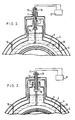
- FIG. 1 illustrates a portion of a conventional cryogenic vessel as disclosed in Japanese Patent Publication No. 54-43359.
- a superconducting magnet 1 is electrically connected to a power supply 12 by power supply leads 11 which extend from the outside of a vacuum insulating vessel 4 to the inside of an inner vessel 3 with a freezing mixture 2 such as liquid helium.
- the power supply leads 11 are supported by a wiring support pipe 13 whose outer end is secured to the vacuum insulating vessel 4 and whose inner end is secured to the inner vessel 3.
- the wiring support pipe 13 is divided into an upper and lower portion which are connected with one another by a flexible tube 14.
- the flexible tube 14 enables the upper and lower portion to move with respect to one another when thermal shrinkage occurs due to the cooling of the various parts of the vessel, thereby preventing thermal stresses from developing in the wiring support pipe 13.
- the upper ends of the power supply leads 11 are secured to the wiring support pipe 13 by a flange 15 mounted on its upper end, and the lower ends of the leads 11 are secured to the wiring support pipe 13 by a connector 16 which is mounted on the inner end thereof and which electrically connects the power supply leads 11 to the superconducting magnet 1.
- the inner vessel 3 is supported by the vacuum insulating vessel 4 through support members 10.
- the flexible tube 14 is effective to prevent thermal stresses from developing in the wiring support tube 13, it results in thrmal stresses arising in the power supply leads 11, since the change in dimensions of the power supply leads 11 due to thermal shringkage is much less than that of the wiring support pipe 13 and the flexible tube 14. For this reason, it is very difficult to reliably connect the power supply leads 11 to the connector 16.
- a cryogenic vessel for a superconducting apparatus comprising an inner vessel for containing a superconducting winding of a superconducting device and a cryogenic medium, a vacuum insulating vessel which surrounds the inner vessel so as to thermally insulate it, a connecting pipe which extends into the inner vessel whose inner end opens onto the inside of the inner vessel and whose outer end opens onto the outside of the vacuum insulating vessel, and a dividing pipe having its outer end secured to the outer surface of the inner vessel and its inner end extending into the inner vessel, the connecting pipe extending along the inside of the dividing pipe with a radial clearance between the outer surface of the connecting pipe and the inner surface of the dividing pipe, and the inner end of the connecting pipe being connected to the inner end of the dividing pipe, characterised in that a rupture-type safety valve is disposed at one of the ends of the connecting pipe, and the cryogenic vessel comprises either one of:
- a wiring support pipe for the power supply leads of a cryogenic vessel in an embodiment of the present invention is a single, rigid pipe which has one of its ends connected to an inner vessel or a vacuum insulating vessel by a flexible tube which absorbs thermal shrinkage. Since the wiring support pipe is a single, rigid pipe, it undergoes thermal shrinkage by about the same amount as the power supply leads which it supports, and thermal stresses do not develop in the power supply leads.
- Embodiments of the present invention may be applied to various types of cooling means for cryogenic vessels as described in copending European Patent Application No. 86300320.8 (published under no. 0 188 389). BRIEF DESCRIPTION OF DRAWINGS
- FIG. 2 illustrates the essential features of a first embodiment of a cryogenic vessel according to the present invention. Those portions of the vessel not shown in this figure can be same as those of any one of the first four embodiments described and illustrated in the copending European Patent Application No 86300320.8 (published under no. 0 188 389).
- This figure shows the portion of cryogenic vessel which is penetrated by power supply leads 11.
- the power supply leads 11 are housed inside a wiring support pipe 70 having a flange 15 formed at its upper end to which the upper ends of the power supply leads 11 are secured, and having a connector 16 installed at its bottom end by means of which the power supply leads 11 are electrically connected to a superconducting magnet 1 housed within an inner vessel 3.
- the inner vessel 3 is supported by a vacuum insulating vessel 4 through supporting members 10.
- the wiring support pipe comprises separate upper and lower portions connected by a flexible tube 14, in the present embodiment, the wiring support pipe 70 is a single, rigid pipe.
- the wiring support pipe 70 is rigidly secured near its upper end to the outer surface of the vacuum insulating vessel 4. Its midportion is connected to the outer surface of the inner vessel 3 by a flexible tube 71 which projects outwards from the inner vessel 3.
- the inner vessel 3 is able to freely move with respect to the wiring support tube 70 so that when the supporting members 10 or the inner vessel 3 undergoes thermal shrinkage, the change in dimensions of the inner vessel 3 has no effect on the wiring support pipe 70 or the power supply leads 11.
- the wiring support pipe 70 and the power supply leads 11 also undergo thermal shrinkage, but as they have approximately the same coefficient of thermal expansion, they undergo approximately the same amount of shrinkage, and no signifcant thermal stresses are induced therein. Accordingly, the present embodiment overcomes the problem of the conventional cryogenic vessel of Figure 1 in which thermal stresses develop in the power supply leads 11, making it difficult to achieve a good connection between the power supply leads 11 and the connector 16.
- Figure 3 illustrates a second embodiment of the present invention which differs from the previous embodiment only in that the flexible tube 71 is disposed inside the inner vessel 3, extending inwards from the outer surface of the inner vessel 3 and connecting to the wiring support pipe 70 near its inner end.
- the effects provided by this embodiment are the same as those of the previous embodiment.
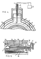
- FIG. 4 illustrates a third embodiment of the present invention in which the manner of connection is reversed. Namely, the inner end of a wiring support pipe 70 is rigidly connected to an inner vessel 3, and the outer end of the wiring support pipe is connected to a vacuum insulating vessel 4 through a flexible tube 71 which projects outwards from the vacuum insulating vessel 4. The effects are identical to those of the previous two embodiments.
- FIG. 5 shows a fourth embodiment of the present invention in which a flexible tube 80 is provided between the outer end of the dividing pipe 21 and the surface of the inner vessel 3.
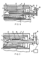
- Figure 6 shows a fifth embodiment of the present invention in which an outward-projecting flexible tube 80 is connected between the outer end of the connecting pipe 7 and the outer surface of the vacuum insulating vessel 4.
- an outward-projecting flexible tube 80 is connected between the outer end of the connecting pipe 7 and the outer surface of the vacuum insulating vessel 4.
- FIG. 7 shows a sixth embodiment of a cryogenic vessel according to the present invention in which a connecting pipe 7 serves not only as a means for discharging gas into the atmosphere but also as a support for the power supply leads 11 for a superconducting magnet 1.
- Power supply leads 11 extend from the outer end of the connecting pipe 7, where they are electrically connected to a power supply 12, to the inner end of the connecting pipe 7, where they are connected to a connector 16 which is electrically connected to the superconducting magnet 1.
- a dividing pipe 21 is connected to the surface of an inner vessel 3 by a flexible tube 80 which compensates for any thermal shrinkage.
- the flexible tube 80 can be used to connect the outer surface of the vacuum insulating vessel 4 to the outer end of the connecting pipe 7, in a manner similar to that shown in Figure 6.
- the structure is otherwise identical to that of the embodiment of Figure 4 of the aforementioned application.
- the cryogenic vessel houses a superconducting magnet 1, but the present invention is not limited to use with a magnet, and it can also be used to house the windings of other types of superconducting devices.
Landscapes
- Physics & Mathematics (AREA)
- Engineering & Computer Science (AREA)
- Power Engineering (AREA)
- Electromagnetism (AREA)
- Condensed Matter Physics & Semiconductors (AREA)
- General Physics & Mathematics (AREA)
- Containers, Films, And Cooling For Superconductive Devices (AREA)
Description
- This invention relates to a cryogenic vessel for a superconducting apparatus, and more particularly but not exclusively, it relates to a cryogenic vessel for cooling the superconducting magnet of a superconducting apparatus such as a nuclear magnetic resonance diagnosis apparatus.
- Figure 1 illustrates a portion of a conventional cryogenic vessel as disclosed in Japanese Patent Publication No. 54-43359. As shown in this figure, a superconducting magnet 1 is electrically connected to a
power supply 12 by power supply leads 11 which extend from the outside of a vacuum insulating vessel 4 to the inside of aninner vessel 3 with a freezingmixture 2 such as liquid helium. Thepower supply leads 11 are supported by awiring support pipe 13 whose outer end is secured to the vacuum insulating vessel 4 and whose inner end is secured to theinner vessel 3. Thewiring support pipe 13 is divided into an upper and lower portion which are connected with one another by a flexible tube 14. The flexible tube 14 enables the upper and lower portion to move with respect to one another when thermal shrinkage occurs due to the cooling of the various parts of the vessel, thereby preventing thermal stresses from developing in thewiring support pipe 13. The upper ends of thepower supply leads 11 are secured to thewiring support pipe 13 by aflange 15 mounted on its upper end, and the lower ends of theleads 11 are secured to thewiring support pipe 13 by aconnector 16 which is mounted on the inner end thereof and which electrically connects the power supply leads 11 to the superconducting magnet 1. Theinner vessel 3 is supported by the vacuum insulating vessel 4 throughsupport members 10. - While the flexible tube 14 is effective to prevent thermal stresses from developing in the
wiring support tube 13, it results in thrmal stresses arising in the power supply leads 11, since the change in dimensions of the power supply leads 11 due to thermal shringkage is much less than that of thewiring support pipe 13 and the flexible tube 14. For this reason, it is very difficult to reliably connect the power supply leads 11 to theconnector 16. - It is an object of the present invention to provide a cryogenic vessel for a superconducting apparatus which is more compact than a conventional cryogenic vessel having a connecting pipe of the same length.
- It is another object of the present invention to provide a cryogenic vessel for a superconducting apparatus in which thermal stresses do not develop in its power supply leads.
- According to the present invention, there is provided a cryogenic vessel for a superconducting apparatus comprising an inner vessel for containing a superconducting winding of a superconducting device and a cryogenic medium, a vacuum insulating vessel which surrounds the inner vessel so as to thermally insulate it, a connecting pipe which extends into the inner vessel whose inner end opens onto the inside of the inner vessel and whose outer end opens onto the outside of the vacuum insulating vessel, and a dividing pipe having its outer end secured to the outer surface of the inner vessel and its inner end extending into the inner vessel, the connecting pipe extending along the inside of the dividing pipe with a radial clearance between the outer surface of the connecting pipe and the inner surface of the dividing pipe, and the inner end of the connecting pipe being connected to the inner end of the dividing pipe, characterised in that a rupture-type safety valve is disposed at one of the ends of the connecting pipe, and the cryogenic vessel comprises either one of:
- a) a power supply lead for the superconducting winding, a rigid wiring support pipe which surrounds the power supply lead and which penetrates the inner vessel and the vacuum insulating vessel, and a flexible tube, the outer end of the wiring support pipe being connected to the vacuum insulating vessel by the flexible tube and the inner end of the wiring support pipe being rigidly connected to the inner vessel; or
- b) a power supply lead for the superconducting winding, a rigid wiring support pipe which surrounds and supports the power supply lead and which penetrates the inner vessel and the vacuum insulating vessel, and a flexible tube, the inner end of the wiring support pipe being connected to the inner vessel by the flexible tube and the outer end of the wiring support pipe being rigidly connected to the vacuum insulating vessel.
- A wiring support pipe for the power supply leads of a cryogenic vessel in an embodiment of the present invention is a single, rigid pipe which has one of its ends connected to an inner vessel or a vacuum insulating vessel by a flexible tube which absorbs thermal shrinkage. Since the wiring support pipe is a single, rigid pipe, it undergoes thermal shrinkage by about the same amount as the power supply leads which it supports, and thermal stresses do not develop in the power supply leads.
- Embodiments of the present invention may be applied to various types of cooling means for cryogenic vessels as described in copending European Patent Application No. 86300320.8 (published under no. 0 188 389). BRIEF DESCRIPTION OF DRAWINGS
- Figure 1 is a transverse cross-sectional view of a portion of a conventional cryogenic vessel.
- Figure 2 is a transverse cross-sectional view of a portion of a first embodiment of a cryogenic vessel.
- Figure 3 is a transverse cross-sectional view of a portion of a second embodiment of a cryogenic vessel.
- Figure 4 is a transverse cross-sectional view of a portion of a third embodiment of a cryogenic vessel.
- Figure 5 is a longitudinal cross-sectional view of a portion of a fourth embodiment of a cryogenic vessel.
- Figure 6 is a longitudinal cross-sectional view of a portion of a fifth embodiment of a cryogenic vessel.
- Figure 7 is a longitudinal cross-sectional view of a portion of an sixth embodiment of a cryogenic vessel.
- In all of the figures, the same reference numerals indicate the same or corresponding parts.
- A number of preferred embodiments of a cryogenic vessel in accordance with the present invention will now be described while referring to Figures 2 through 7 of the accompanying drawings.
- Figure 2 illustrates the essential features of a first embodiment of a cryogenic vessel according to the present invention. Those portions of the vessel not shown in this figure can be same as those of any one of the first four embodiments described and illustrated in the copending European Patent Application No 86300320.8 (published under no. 0 188 389). This figure shows the portion of cryogenic vessel which is penetrated by power supply leads 11. The power supply leads 11 are housed inside a
wiring support pipe 70 having aflange 15 formed at its upper end to which the upper ends of thepower supply leads 11 are secured, and having aconnector 16 installed at its bottom end by means of which the power supply leads 11 are electrically connected to a superconducting magnet 1 housed within aninner vessel 3. Theinner vessel 3 is supported by a vacuum insulating vessel 4 through supportingmembers 10. Whereas in the conventional apparatus of Figure 1 the wiring support pipe comprises separate upper and lower portions connected by a flexible tube 14, in the present embodiment, thewiring support pipe 70 is a single, rigid pipe. Thewiring support pipe 70 is rigidly secured near its upper end to the outer surface of the vacuum insulating vessel 4. Its midportion is connected to the outer surface of theinner vessel 3 by aflexible tube 71 which projects outwards from theinner vessel 3. - With this construction, the
inner vessel 3 is able to freely move with respect to thewiring support tube 70 so that when the supportingmembers 10 or theinner vessel 3 undergoes thermal shrinkage, the change in dimensions of theinner vessel 3 has no effect on thewiring support pipe 70 or the power supply leads 11. - When the inside of the cryogenic vessel is cooled, the
wiring support pipe 70 and the power supply leads 11 also undergo thermal shrinkage, but as they have approximately the same coefficient of thermal expansion, they undergo approximately the same amount of shrinkage, and no signifcant thermal stresses are induced therein. Accordingly, the present embodiment overcomes the problem of the conventional cryogenic vessel of Figure 1 in which thermal stresses develop in the power supply leads 11, making it difficult to achieve a good connection between the power supply leads 11 and theconnector 16. - Figure 3 illustrates a second embodiment of the present invention which differs from the previous embodiment only in that the
flexible tube 71 is disposed inside theinner vessel 3, extending inwards from the outer surface of theinner vessel 3 and connecting to thewiring support pipe 70 near its inner end. The effects provided by this embodiment are the same as those of the previous embodiment. - In the previous two embodiments, the outer end of a rigid
wiring support pipe 70 is rigidly secured to the outer surface of a vacuum insulating vessel 4 and the inner end of thewiring support pipe 70 is connected to aninner vessel 3 through aflexible tube 71. Figure 4 illustrates a third embodiment of the present invention in which the manner of connection is reversed. Namely, the inner end of awiring support pipe 70 is rigidly connected to aninner vessel 3, and the outer end of the wiring support pipe is connected to a vacuum insulating vessel 4 through aflexible tube 71 which projects outwards from the vacuum insulating vessel 4. The effects are identical to those of the previous two embodiments. - In each of the previous embodiments, the inner end of a connecting pipe 7 is rigidly secured to an
inner vessel 3 through a dividingpipe 21, and the outer end of the connecting pipe 7 is rigidly secured to a vacuum insulating vessel 4. However, as shown in Figures 5 and 6 it is possible to connect the connecting pipe 7 to theinner vessel 3 or the vacuum insulating vessel 4 in an elastic manner so that thermal shrinkage can be compensated for without producing thermal stresses in the connecting pipe 7. Figure 5 shows a fourth embodiment of the present invention in which aflexible tube 80 is provided between the outer end of the dividingpipe 21 and the surface of theinner vessel 3. Furthermore, Figure 6 shows a fifth embodiment of the present invention in which an outward-projectingflexible tube 80 is connected between the outer end of the connecting pipe 7 and the outer surface of the vacuum insulating vessel 4. These two embodiments are otherwise identical to the embodiment of figure 10 of the copending European Patent Application 86300320.8. The same effects as in that embodiment are achieved. In the same manner, aflexible tube 80 can be employed between the dividingpipe 21 and theinner vessel 3, or between the connecting pipe 7 and the vacuum insulating vessel 4 of a cryogenic vessel having the structure of any one of the other previously- described embodiments. - Figure 7 shows a sixth embodiment of a cryogenic vessel according to the present invention in which a connecting pipe 7 serves not only as a means for discharging gas into the atmosphere but also as a support for the power supply leads 11 for a superconducting magnet 1. Power supply leads 11 extend from the outer end of the connecting pipe 7, where they are electrically connected to a
power supply 12, to the inner end of the connecting pipe 7, where they are connected to aconnector 16 which is electrically connected to the superconducting magnet 1. In order to prevent thermal stresses from developing in the power supply leads 11, a dividingpipe 21 is connected to the surface of aninner vessel 3 by aflexible tube 80 which compensates for any thermal shrinkage. Alternatively, theflexible tube 80 can be used to connect the outer surface of the vacuum insulating vessel 4 to the outer end of the connecting pipe 7, in a manner similar to that shown in Figure 6. The structure is otherwise identical to that of the embodiment of Figure 4 of the aforementioned application. By installing the power supply leads 11 inside the connecting pipe 7, a separatewiring support pipe 70 as in Figure 2 is made unnecessary, and the vessel can be made more compact. - In each of the previous embodiments, the cryogenic vessel houses a superconducting magnet 1, but the present invention is not limited to use with a magnet, and it can also be used to house the windings of other types of superconducting devices.
Claims (3)
Applications Claiming Priority (10)
| Application Number | Priority Date | Filing Date | Title |
|---|---|---|---|
| JP60004888A JPS61164277A (en) | 1985-01-17 | 1985-01-17 | Cryogenic container |
| JP4888/85 | 1985-01-17 | ||
| JP76749/85 | 1985-04-12 | ||
| JP60076749A JPS61236175A (en) | 1985-04-12 | 1985-04-12 | Cryogenic container |
| JP100543/85 | 1985-05-14 | ||
| JP60100542A JPS61259581A (en) | 1985-05-14 | 1985-05-14 | Superconductive magnet unit |
| JP100542/85 | 1985-05-14 | ||
| JP60100543A JPS61259582A (en) | 1985-05-14 | 1985-05-14 | Superconductive magnet unit |
| JP205661/85 | 1985-09-17 | ||
| JP60205661A JPS6265389A (en) | 1985-09-17 | 1985-09-17 | Cryogenic container |
Related Parent Applications (2)
| Application Number | Title | Priority Date | Filing Date |
|---|---|---|---|
| EP86300320.8 Division | 1986-01-17 | ||
| EP86300320A Division-Into EP0188389B1 (en) | 1985-01-17 | 1986-01-17 | Cryogenic vessel for a superconducting apparatus |
Publications (3)
| Publication Number | Publication Date |
|---|---|
| EP0375656A2 EP0375656A2 (en) | 1990-06-27 |
| EP0375656A3 EP0375656A3 (en) | 1990-07-11 |
| EP0375656B1 true EP0375656B1 (en) | 1993-11-24 |
Family
ID=27518538
Family Applications (2)
| Application Number | Title | Priority Date | Filing Date |
|---|---|---|---|
| EP19900101082 Expired - Lifetime EP0375656B1 (en) | 1985-01-17 | 1986-01-17 | Cryogenic vessel for a superconducting apparatus |
| EP86300320A Expired - Lifetime EP0188389B1 (en) | 1985-01-17 | 1986-01-17 | Cryogenic vessel for a superconducting apparatus |
Family Applications After (1)
| Application Number | Title | Priority Date | Filing Date |
|---|---|---|---|
| EP86300320A Expired - Lifetime EP0188389B1 (en) | 1985-01-17 | 1986-01-17 | Cryogenic vessel for a superconducting apparatus |
Country Status (3)
| Country | Link |
|---|---|
| US (1) | US4655045A (en) |
| EP (2) | EP0375656B1 (en) |
| DE (2) | DE3689337T2 (en) |
Families Citing this family (22)
| Publication number | Priority date | Publication date | Assignee | Title |
|---|---|---|---|---|
| DE3724562C1 (en) * | 1987-07-24 | 1989-01-12 | Spectrospin Ag | Cryostat and assembly method |
| US4782671A (en) * | 1987-09-28 | 1988-11-08 | General Atomics | Cooling apparatus for MRI magnet system and method of use |
| US4841268A (en) * | 1987-09-28 | 1989-06-20 | General Atomics | MRI Magnet system with permanently installed power leads |
| US5012948A (en) * | 1989-06-21 | 1991-05-07 | General Dynamics Corporation, Convair Division | Support arrangement for a space based cryogenic vessel |
| GB2233750B (en) * | 1989-06-21 | 1993-02-03 | Hitachi Ltd | Cryostat with cryo-cooler |
| US4986078A (en) * | 1989-08-17 | 1991-01-22 | General Electric Company | Refrigerated MR magnet support system |
| GB8920345D0 (en) * | 1989-09-08 | 1989-10-25 | Oxford Advanced Tech | Magnetic field generating system |
| JP3102492B2 (en) * | 1990-07-20 | 2000-10-23 | 株式会社日立製作所 | Anti-vibration cryostat |
| GB2267570B (en) * | 1992-04-16 | 1996-03-06 | Jeremy Andrew Good | Improvements in and relating to super-conducting magnets |
| DE4227388C2 (en) * | 1992-08-19 | 1996-09-12 | Spectrospin Ag | Cryostat with mechanically flexible thermal contact |
| GB9707751D0 (en) * | 1997-04-17 | 1997-06-04 | Boc Group Plc | Transportation of liquid cryogens |
| JP3509092B2 (en) * | 1998-12-11 | 2004-03-22 | 住友電気工業株式会社 | Superconductor cooling device |
| US6011454A (en) * | 1998-12-30 | 2000-01-04 | Huang; Xianrui | Superconducting magnet suspension assembly |
| GB2460022B (en) * | 2008-05-12 | 2010-04-07 | Siemens Magnet Technology Ltd | Passive overpressure and underpressure protection for a cryogen vessel |
| DE102010007498B4 (en) * | 2010-02-09 | 2012-04-19 | Lurgi Gmbh | Nozzle arrangement for an internal component |
| JP5549552B2 (en) * | 2010-11-12 | 2014-07-16 | 東京エレクトロン株式会社 | Method for assembling vacuum processing apparatus and vacuum processing apparatus |
| GB2499815B (en) | 2012-02-29 | 2014-05-28 | Siemens Plc | Over-pressure limiting arrangement for a cryogen vessel |
| JP6134211B2 (en) | 2013-06-19 | 2017-05-24 | 川崎重工業株式会社 | Double shell tank and liquefied gas carrier |
| US10748690B2 (en) * | 2013-07-26 | 2020-08-18 | Koninklijke Philips N.V. | Method and device for controlling cooling loop for superconducting magnet system in response to magnetic field |
| US20190033404A1 (en) * | 2016-03-15 | 2019-01-31 | Koninklijke Philips N.V. | Articulated guide tube |
| CN111442184B (en) * | 2020-04-20 | 2024-12-20 | 辰一(上海)石油天然气工程技术有限公司 | A pipe connection structure for double-layer spherical tank and double-layer spherical tank |
| KR20240178960A (en) * | 2023-06-23 | 2024-12-31 | 하이리움산업(주) | Wire discharge system of cryogenic fluid storage tank |
Citations (1)
| Publication number | Priority date | Publication date | Assignee | Title |
|---|---|---|---|---|
| US4526015A (en) * | 1984-10-15 | 1985-07-02 | General Electric Company | Support for cryostat penetration tube |
Family Cites Families (17)
| Publication number | Priority date | Publication date | Assignee | Title |
|---|---|---|---|---|
| US3122004A (en) * | 1961-03-27 | 1964-02-25 | Union Carbide Corp | Apparatus for cryogenic refrigeration |
| US3309884A (en) * | 1965-10-11 | 1967-03-21 | Richard S Pauliukonis | Dewar design for storage and transportation of low temperature fluids |
| DE1501319B2 (en) * | 1966-03-22 | 1971-03-11 | Siemens AG. 1000 Berlin u 8000 München | CRYOSTAT WITH A LOW-BOILING LIQUID COOLANT IN PARTICULAR FOR THE COOLING OF SUPRAL LINE COILS |
| US3364688A (en) * | 1966-04-15 | 1968-01-23 | Ryan Ind Inc | Cryogenic container means |
| US3358463A (en) * | 1966-07-15 | 1967-12-19 | Lockheed Aircraft Corp | Integrated superconducting magnetcryostat system |
| US3433028A (en) * | 1966-09-02 | 1969-03-18 | Air Prod & Chem | Cryogenic fluid conveying system |
| US3446387A (en) * | 1967-05-17 | 1969-05-27 | Webb James E | Piping arrangement through a double wall chamber |
| US3483709A (en) * | 1967-07-21 | 1969-12-16 | Princeton Gamma Tech Inc | Low temperature system |
| US3481149A (en) * | 1968-05-09 | 1969-12-02 | Gen Pneumatics Corp | Gas generator |
| US3762175A (en) * | 1971-07-08 | 1973-10-02 | P Jones | Liquefied gas containers |
| JPS5031372B2 (en) * | 1972-06-22 | 1975-10-09 | ||
| GB2045413A (en) * | 1979-03-26 | 1980-10-29 | Boc Ltd | Vacuum-insulated containers |
| JPS5917550A (en) * | 1982-07-21 | 1984-01-28 | Mitsubishi Chem Ind Ltd | Photocrosslinkable photosensitive material |
| EP0122498B1 (en) * | 1983-04-15 | 1988-06-08 | Hitachi, Ltd. | Cryostat |
| US4535596A (en) * | 1984-03-30 | 1985-08-20 | General Electric Company | Plug for horizontal cryostat penetration |
| US4522034A (en) * | 1984-03-30 | 1985-06-11 | General Electric Company | Horizontal cryostat penetration insert and assembly |
| US4516404A (en) * | 1984-03-30 | 1985-05-14 | General Electric Company | Foam filled insert for horizontal cryostat penetrations |
-
1986
- 1986-01-17 EP EP19900101082 patent/EP0375656B1/en not_active Expired - Lifetime
- 1986-01-17 US US06/819,856 patent/US4655045A/en not_active Expired - Fee Related
- 1986-01-17 EP EP86300320A patent/EP0188389B1/en not_active Expired - Lifetime
- 1986-01-17 DE DE3689337T patent/DE3689337T2/en not_active Expired - Fee Related
- 1986-01-17 DE DE8686300320T patent/DE3679833D1/en not_active Expired - Lifetime
Patent Citations (1)
| Publication number | Priority date | Publication date | Assignee | Title |
|---|---|---|---|---|
| US4526015A (en) * | 1984-10-15 | 1985-07-02 | General Electric Company | Support for cryostat penetration tube |
Also Published As
| Publication number | Publication date |
|---|---|
| US4655045A (en) | 1987-04-07 |
| EP0375656A2 (en) | 1990-06-27 |
| DE3679833D1 (en) | 1991-07-25 |
| EP0188389B1 (en) | 1991-06-19 |
| DE3689337T2 (en) | 1994-06-23 |
| EP0188389A3 (en) | 1987-11-25 |
| EP0375656A3 (en) | 1990-07-11 |
| DE3689337D1 (en) | 1994-01-05 |
| EP0188389A2 (en) | 1986-07-23 |
Similar Documents
| Publication | Publication Date | Title |
|---|---|---|
| EP0375656A2 (en) | Cryogenic vessel for a superconducting apparatus | |
| US5691679A (en) | Ceramic superconducting lead resistant to moisture and breakage | |
| JPH0418189B2 (en) | ||
| CN100550452C (en) | Cryogenics for superconducting devices | |
| US4522034A (en) | Horizontal cryostat penetration insert and assembly | |
| EP0414443A1 (en) | Refrigerated MR magnet support system | |
| EP0781956B1 (en) | Convection cooling of bellows convolutions using sleeve penetration tube | |
| EP0450972B1 (en) | Superconductive magnet | |
| US5571606A (en) | Ceramic superconducting lead resistant to breakage | |
| US4295068A (en) | Cantilevered field winding support for a superconducting AC machine | |
| GB2102109A (en) | Cryostats | |
| US4667486A (en) | Refrigerated penetration insert for cryostat with axial thermal disconnect | |
| EP0450971B1 (en) | Superconductive magnet | |
| US5369387A (en) | Shim lead power coupling assembly for superconducting magnet | |
| US4633682A (en) | Horizontal cryostat insert with a vertical service stack | |
| US4745313A (en) | Stator having three-phase superconducting windings | |
| US5333464A (en) | Cold head sleeve and high-TC superconducting lead assemblies for a superconducting magnet which images human limbs | |
| CA2010145A1 (en) | Cryogenic precooler for superconductive magnets | |
| JPS6046603B2 (en) | Reactor wall penetration device for measurement cables | |
| US4675637A (en) | Superconducting static machine having a magnetic circuit | |
| JPS6119089B2 (en) | ||
| JPH0442511A (en) | Superconducting magnet | |
| EP0805546A1 (en) | Support structure for a superconducting coil | |
| CN119716688A (en) | Testing device for fast pulse superconducting magnet | |
| JPS603555Y2 (en) | superconducting coil |
Legal Events
| Date | Code | Title | Description |
|---|---|---|---|
| PUAI | Public reference made under article 153(3) epc to a published international application that has entered the european phase |
Free format text: ORIGINAL CODE: 0009012 |
|
| PUAL | Search report despatched |
Free format text: ORIGINAL CODE: 0009013 |
|
| 17P | Request for examination filed |
Effective date: 19900208 |
|
| AC | Divisional application: reference to earlier application |
Ref document number: 188389 Country of ref document: EP |
|
| AK | Designated contracting states |
Kind code of ref document: A2 Designated state(s): DE GB NL |
|
| AK | Designated contracting states |
Kind code of ref document: A3 Designated state(s): DE GB NL |
|
| 17Q | First examination report despatched |
Effective date: 19910628 |
|
| GRAA | (expected) grant |
Free format text: ORIGINAL CODE: 0009210 |
|
| AC | Divisional application: reference to earlier application |
Ref document number: 188389 Country of ref document: EP |
|
| AK | Designated contracting states |
Kind code of ref document: B1 Designated state(s): DE GB NL |
|
| REF | Corresponds to: |
Ref document number: 3689337 Country of ref document: DE Date of ref document: 19940105 |
|
| REG | Reference to a national code |
Ref country code: GB Ref legal event code: 727 |
|
| REG | Reference to a national code |
Ref country code: GB Ref legal event code: 727A |
|
| REG | Reference to a national code |
Ref country code: GB Ref legal event code: 727B |
|
| REG | Reference to a national code |
Ref country code: GB Ref legal event code: SP |
|
| PLBE | No opposition filed within time limit |
Free format text: ORIGINAL CODE: 0009261 |
|
| STAA | Information on the status of an ep patent application or granted ep patent |
Free format text: STATUS: NO OPPOSITION FILED WITHIN TIME LIMIT |
|
| 26N | No opposition filed | ||
| PGFP | Annual fee paid to national office [announced via postgrant information from national office to epo] |
Ref country code: NL Payment date: 19950131 Year of fee payment: 10 |
|
| REG | Reference to a national code |
Ref country code: GB Ref legal event code: 746 Effective date: 19951107 |
|
| PGFP | Annual fee paid to national office [announced via postgrant information from national office to epo] |
Ref country code: GB Payment date: 19960108 Year of fee payment: 11 |
|
| PGFP | Annual fee paid to national office [announced via postgrant information from national office to epo] |
Ref country code: DE Payment date: 19960126 Year of fee payment: 11 |
|
| PG25 | Lapsed in a contracting state [announced via postgrant information from national office to epo] |
Ref country code: NL Effective date: 19960801 |
|
| NLV4 | Nl: lapsed or anulled due to non-payment of the annual fee |
Effective date: 19960801 |
|
| PG25 | Lapsed in a contracting state [announced via postgrant information from national office to epo] |
Ref country code: GB Effective date: 19970117 |
|
| GBPC | Gb: european patent ceased through non-payment of renewal fee |
Effective date: 19970117 |
|
| PG25 | Lapsed in a contracting state [announced via postgrant information from national office to epo] |
Ref country code: DE Effective date: 19971001 |