EP0375585B1 - Method for manufacturing a BI-CMOS device - Google Patents
Method for manufacturing a BI-CMOS device Download PDFInfo
- Publication number
- EP0375585B1 EP0375585B1 EP89480174A EP89480174A EP0375585B1 EP 0375585 B1 EP0375585 B1 EP 0375585B1 EP 89480174 A EP89480174 A EP 89480174A EP 89480174 A EP89480174 A EP 89480174A EP 0375585 B1 EP0375585 B1 EP 0375585B1
- Authority
- EP
- European Patent Office
- Prior art keywords
- layer
- oxide
- polysilicon
- process according
- emitter
- Prior art date
- Legal status (The legal status is an assumption and is not a legal conclusion. Google has not performed a legal analysis and makes no representation as to the accuracy of the status listed.)
- Expired - Lifetime
Links
- 238000000034 method Methods 0.000 title claims description 34
- 238000004519 manufacturing process Methods 0.000 title claims description 16
- 239000007943 implant Substances 0.000 claims description 42
- 229910021420 polycrystalline silicon Inorganic materials 0.000 claims description 33
- 229920005591 polysilicon Polymers 0.000 claims description 33
- 230000008569 process Effects 0.000 claims description 26
- 238000002955 isolation Methods 0.000 claims description 17
- 239000000758 substrate Substances 0.000 claims description 15
- 150000004767 nitrides Chemical class 0.000 claims description 14
- 239000002019 doping agent Substances 0.000 claims description 13
- 238000000151 deposition Methods 0.000 claims description 10
- 230000000873 masking effect Effects 0.000 claims description 8
- 230000008021 deposition Effects 0.000 claims description 6
- NJPPVKZQTLUDBO-UHFFFAOYSA-N novaluron Chemical compound C1=C(Cl)C(OC(F)(F)C(OC(F)(F)F)F)=CC=C1NC(=O)NC(=O)C1=C(F)C=CC=C1F NJPPVKZQTLUDBO-UHFFFAOYSA-N 0.000 claims description 6
- 125000006850 spacer group Chemical group 0.000 claims description 6
- 150000002500 ions Chemical class 0.000 claims description 5
- 229910021332 silicide Inorganic materials 0.000 claims description 5
- FVBUAEGBCNSCDD-UHFFFAOYSA-N silicide(4-) Chemical compound [Si-4] FVBUAEGBCNSCDD-UHFFFAOYSA-N 0.000 claims description 5
- 238000005530 etching Methods 0.000 claims description 4
- 229920002120 photoresistant polymer Polymers 0.000 claims description 4
- 238000004518 low pressure chemical vapour deposition Methods 0.000 claims description 3
- 239000004065 semiconductor Substances 0.000 claims description 3
- QVGXLLKOCUKJST-UHFFFAOYSA-N atomic oxygen Chemical compound [O] QVGXLLKOCUKJST-UHFFFAOYSA-N 0.000 claims description 2
- 230000000295 complement effect Effects 0.000 claims description 2
- 229910052760 oxygen Inorganic materials 0.000 claims description 2
- 239000001301 oxygen Substances 0.000 claims description 2
- 238000001020 plasma etching Methods 0.000 claims 3
- KRHYYFGTRYWZRS-UHFFFAOYSA-N Fluorane Chemical compound F KRHYYFGTRYWZRS-UHFFFAOYSA-N 0.000 claims 2
- 238000000059 patterning Methods 0.000 claims 2
- 230000005669 field effect Effects 0.000 claims 1
- 230000001590 oxidative effect Effects 0.000 claims 1
- 229910021341 titanium silicide Inorganic materials 0.000 claims 1
- WQJQOUPTWCFRMM-UHFFFAOYSA-N tungsten disilicide Chemical group [Si]#[W]#[Si] WQJQOUPTWCFRMM-UHFFFAOYSA-N 0.000 claims 1
- 229910021342 tungsten silicide Inorganic materials 0.000 claims 1
- 238000012545 processing Methods 0.000 description 18
- 230000001965 increasing effect Effects 0.000 description 5
- ZOXJGFHDIHLPTG-UHFFFAOYSA-N Boron Chemical compound [B] ZOXJGFHDIHLPTG-UHFFFAOYSA-N 0.000 description 4
- 229910052796 boron Inorganic materials 0.000 description 4
- 230000009467 reduction Effects 0.000 description 4
- 229910052785 arsenic Inorganic materials 0.000 description 3
- RQNWIZPPADIBDY-UHFFFAOYSA-N arsenic atom Chemical compound [As] RQNWIZPPADIBDY-UHFFFAOYSA-N 0.000 description 3
- 230000015556 catabolic process Effects 0.000 description 3
- 238000013461 design Methods 0.000 description 3
- 238000009792 diffusion process Methods 0.000 description 3
- 238000005516 engineering process Methods 0.000 description 3
- 238000010348 incorporation Methods 0.000 description 3
- 230000010354 integration Effects 0.000 description 3
- 108010075750 P-Type Calcium Channels Proteins 0.000 description 2
- 230000008901 benefit Effects 0.000 description 2
- 230000015572 biosynthetic process Effects 0.000 description 2
- 229910021421 monocrystalline silicon Inorganic materials 0.000 description 2
- 230000003647 oxidation Effects 0.000 description 2
- 238000007254 oxidation reaction Methods 0.000 description 2
- 108091006146 Channels Proteins 0.000 description 1
- NBIIXXVUZAFLBC-UHFFFAOYSA-N Phosphoric acid Chemical compound OP(O)(O)=O NBIIXXVUZAFLBC-UHFFFAOYSA-N 0.000 description 1
- 229910008479 TiSi2 Inorganic materials 0.000 description 1
- 229910008814 WSi2 Inorganic materials 0.000 description 1
- 238000000137 annealing Methods 0.000 description 1
- 229910052787 antimony Inorganic materials 0.000 description 1
- WATWJIUSRGPENY-UHFFFAOYSA-N antimony atom Chemical compound [Sb] WATWJIUSRGPENY-UHFFFAOYSA-N 0.000 description 1
- DFJQEGUNXWZVAH-UHFFFAOYSA-N bis($l^{2}-silanylidene)titanium Chemical compound [Si]=[Ti]=[Si] DFJQEGUNXWZVAH-UHFFFAOYSA-N 0.000 description 1
- 238000005520 cutting process Methods 0.000 description 1
- 230000007547 defect Effects 0.000 description 1
- 238000011982 device technology Methods 0.000 description 1
- 238000007599 discharging Methods 0.000 description 1
- 230000002708 enhancing effect Effects 0.000 description 1
- BHEPBYXIRTUNPN-UHFFFAOYSA-N hydridophosphorus(.) (triplet) Chemical compound [PH] BHEPBYXIRTUNPN-UHFFFAOYSA-N 0.000 description 1
- 238000009413 insulation Methods 0.000 description 1
- 230000004048 modification Effects 0.000 description 1
- 238000012986 modification Methods 0.000 description 1
- 230000002093 peripheral effect Effects 0.000 description 1
- 235000011007 phosphoric acid Nutrition 0.000 description 1
- 238000000206 photolithography Methods 0.000 description 1
- 230000002265 prevention Effects 0.000 description 1
- 230000001681 protective effect Effects 0.000 description 1
- 230000001629 suppression Effects 0.000 description 1
- 230000007704 transition Effects 0.000 description 1
Images


Classifications
-
- H—ELECTRICITY
- H01—ELECTRIC ELEMENTS
- H01L—SEMICONDUCTOR DEVICES NOT COVERED BY CLASS H10
- H01L21/00—Processes or apparatus adapted for the manufacture or treatment of semiconductor or solid state devices or of parts thereof
- H01L21/70—Manufacture or treatment of devices consisting of a plurality of solid state components formed in or on a common substrate or of parts thereof; Manufacture of integrated circuit devices or of parts thereof
- H01L21/77—Manufacture or treatment of devices consisting of a plurality of solid state components or integrated circuits formed in, or on, a common substrate
- H01L21/78—Manufacture or treatment of devices consisting of a plurality of solid state components or integrated circuits formed in, or on, a common substrate with subsequent division of the substrate into plural individual devices
- H01L21/82—Manufacture or treatment of devices consisting of a plurality of solid state components or integrated circuits formed in, or on, a common substrate with subsequent division of the substrate into plural individual devices to produce devices, e.g. integrated circuits, each consisting of a plurality of components
- H01L21/822—Manufacture or treatment of devices consisting of a plurality of solid state components or integrated circuits formed in, or on, a common substrate with subsequent division of the substrate into plural individual devices to produce devices, e.g. integrated circuits, each consisting of a plurality of components the substrate being a semiconductor, using silicon technology
- H01L21/8248—Combination of bipolar and field-effect technology
- H01L21/8249—Bipolar and MOS technology
-
- H—ELECTRICITY
- H01—ELECTRIC ELEMENTS
- H01L—SEMICONDUCTOR DEVICES NOT COVERED BY CLASS H10
- H01L27/00—Devices consisting of a plurality of semiconductor or other solid-state components formed in or on a common substrate
- H01L27/02—Devices consisting of a plurality of semiconductor or other solid-state components formed in or on a common substrate including semiconductor components specially adapted for rectifying, oscillating, amplifying or switching and having potential barriers; including integrated passive circuit elements having potential barriers
- H01L27/04—Devices consisting of a plurality of semiconductor or other solid-state components formed in or on a common substrate including semiconductor components specially adapted for rectifying, oscillating, amplifying or switching and having potential barriers; including integrated passive circuit elements having potential barriers the substrate being a semiconductor body
- H01L27/06—Devices consisting of a plurality of semiconductor or other solid-state components formed in or on a common substrate including semiconductor components specially adapted for rectifying, oscillating, amplifying or switching and having potential barriers; including integrated passive circuit elements having potential barriers the substrate being a semiconductor body including a plurality of individual components in a non-repetitive configuration
- H01L27/0611—Devices consisting of a plurality of semiconductor or other solid-state components formed in or on a common substrate including semiconductor components specially adapted for rectifying, oscillating, amplifying or switching and having potential barriers; including integrated passive circuit elements having potential barriers the substrate being a semiconductor body including a plurality of individual components in a non-repetitive configuration integrated circuits having a two-dimensional layout of components without a common active region
- H01L27/0617—Devices consisting of a plurality of semiconductor or other solid-state components formed in or on a common substrate including semiconductor components specially adapted for rectifying, oscillating, amplifying or switching and having potential barriers; including integrated passive circuit elements having potential barriers the substrate being a semiconductor body including a plurality of individual components in a non-repetitive configuration integrated circuits having a two-dimensional layout of components without a common active region comprising components of the field-effect type
- H01L27/0623—Devices consisting of a plurality of semiconductor or other solid-state components formed in or on a common substrate including semiconductor components specially adapted for rectifying, oscillating, amplifying or switching and having potential barriers; including integrated passive circuit elements having potential barriers the substrate being a semiconductor body including a plurality of individual components in a non-repetitive configuration integrated circuits having a two-dimensional layout of components without a common active region comprising components of the field-effect type in combination with bipolar transistors
-
- H—ELECTRICITY
- H01—ELECTRIC ELEMENTS
- H01L—SEMICONDUCTOR DEVICES NOT COVERED BY CLASS H10
- H01L27/00—Devices consisting of a plurality of semiconductor or other solid-state components formed in or on a common substrate
- H01L27/02—Devices consisting of a plurality of semiconductor or other solid-state components formed in or on a common substrate including semiconductor components specially adapted for rectifying, oscillating, amplifying or switching and having potential barriers; including integrated passive circuit elements having potential barriers
- H01L27/04—Devices consisting of a plurality of semiconductor or other solid-state components formed in or on a common substrate including semiconductor components specially adapted for rectifying, oscillating, amplifying or switching and having potential barriers; including integrated passive circuit elements having potential barriers the substrate being a semiconductor body
- H01L27/06—Devices consisting of a plurality of semiconductor or other solid-state components formed in or on a common substrate including semiconductor components specially adapted for rectifying, oscillating, amplifying or switching and having potential barriers; including integrated passive circuit elements having potential barriers the substrate being a semiconductor body including a plurality of individual components in a non-repetitive configuration
- H01L27/07—Devices consisting of a plurality of semiconductor or other solid-state components formed in or on a common substrate including semiconductor components specially adapted for rectifying, oscillating, amplifying or switching and having potential barriers; including integrated passive circuit elements having potential barriers the substrate being a semiconductor body including a plurality of individual components in a non-repetitive configuration the components having an active region in common
- H01L27/0705—Devices consisting of a plurality of semiconductor or other solid-state components formed in or on a common substrate including semiconductor components specially adapted for rectifying, oscillating, amplifying or switching and having potential barriers; including integrated passive circuit elements having potential barriers the substrate being a semiconductor body including a plurality of individual components in a non-repetitive configuration the components having an active region in common comprising components of the field effect type
- H01L27/0711—Devices consisting of a plurality of semiconductor or other solid-state components formed in or on a common substrate including semiconductor components specially adapted for rectifying, oscillating, amplifying or switching and having potential barriers; including integrated passive circuit elements having potential barriers the substrate being a semiconductor body including a plurality of individual components in a non-repetitive configuration the components having an active region in common comprising components of the field effect type in combination with bipolar transistors and diodes, or capacitors, or resistors
Definitions
- This invention relates to a method for manufacturing a Bi-CMOS semiconductor device and more particularly to a fabrication technique for producing a BI-CMOS device with vertical bipolar NPN and PNP components.
- Bi-CMOS technology (bipolar and CMOS transistors on a single semiconductor substrate) has become an increasingly attractive device technology because it can provide high performance (better than CMOS alone) without high power consumption (much lower than bipolar alone).
- One of the recognized drawbacks in fabricating such Bi-CMOS devices is the increased processing required to produce such high performance CMOS and bipolar components on the same chip.
- the skill in the art has been to combine the separate processing steps as known for each technology into a combined processing sequence. This has resulted in overly complicated processing plans, which plans are undesirable as they contain excessive processing steps and are time-consuming and costly. Therefore, there has been an ever increasing need for a Bi-CMOS device which can be fabricated with a greater integration of the bipolar and CMOS process steps.
- the invention herein incorporates a structure which was specially developed to be compatible with the bipolar and the CMOS device. With this structure, processing steps can now be shared to simplify the Bi-CMOS fabrication.
- U.S.-A No. 4.484.388 discloses a method for forming a Bi-CMOS structure whereas a different Bi-CMOS device is produced by an unrelated process which includes steps to form an emitter self-aligned to the base and form the gate oxide over the emitter.
- a bipolar-CMOS IC device is formed in a p- substrate with an n-layer by: forming n+ buried region for a bipolar transistor and n+ buried region in both substrate and n-layer; forming p+ buried region around n+ region and p+ buried region outside region; forming p+ isolation region extending from the surface of n-layer to buried region; forming vertical npn transistor in layer surrounded by isolation region; forming p-well from the surface of n-layer to buried region; forming n-MOSFET in p-well; and, forming p-MOSFET in portion of n-layer on buried region.
- complementary bipolar-CMOS device is formed on a single substrate with complete prevention oif latch up.
- a method for fabricating a BI-CMOS device using fewer processing steps combined with the incorporation of a vertical PNP and NPN bipolar device is disclosed in claim 1.
- a bipolar structure for the device is configured which is closer to and more compatible with that of the FET.
- some of the generalized processing steps include: forming the reach-through N+ subcollector to the bipolar device without extra processing steps; combining into one mask the threshold adjust/well implants with self-aligned isolation leakage protection implants by using a self-aligned, removable oxide mask prior to field isolation; using a resist etch-back scheme to protect against emitter to base punch-through while self-aligning the pedestal and base; and also providing for the removal of the gate oxide at the emitter while maintaining it at the FET, without extra masks.
- the combination of the bipolar devices with the CMOS device can now be expanded.
- a vertical PNP can now be added to the device in addition to the CMOS component and vertical NPN. This permits additional flexibility in circuit design, as for example, where the vertical PNP's subcollector is tied to the substrate to create a particular circuit.
- the device structure is such that the bipolar and CMOS components can share similar structural features.
- the NPN and pFET share the same well and share a diffusion (the p+ extrinsic base is the same as the p+ source).
- the pnp and nFET share the same well and an n+ diffusion. This permits the merging of components which results in reduced component count and increased density.
- the circuit design is an emitter follower circuit, the subcollectors are tied to a constant voltage, which means that the collector capacitance is not critical since there is no charging and discharging.
- trench isolation (often used to reduce collector area by cutting it off and, therefore, collector capacitance) is not necessary. This makes the processing sequence simpler as recessed oxide isolation can be used.
- LDD lightly doped drain
- the vertical PNP is incorporated into the Bi-CMOS device without limitation to a particular circuit.
- trench isolation will be used to provide lateral isolation.
- the isolation to the substrate can then be accomplished either by using an oxygen implant to form a buried insulation layer or by starting with an n- (on p+) epi and ensuring that the p+ subcollector does not extend through the n- epi and touch the p+ substrate.
- Figures 1-11 are cross-sectional views in the fabrication sequence of the subject Bi-CMOS device.
- a P- epi layer 3 onto a P+ substrate 1 is deposited a P- epi layer 3.
- the starting wafer is a P- epi on a P+ substrate except if the PNP is to be isolated by N- epi on P+ substrate.
- the epi layer thickness is chosen so that, at the process end, the n+ subcollector junction depth is about 1 ⁇ m more shallow than the P-/P+ transition to avoid high capacitance/low voltage breakdown. This yields an epi layer thickness on the order of 3-6 ⁇ m.
- the subcollector areas 15 and 17 are driven-in and oxidized to thicknesses 19 and 21 of approximately 2000 Angström - 5000 Angström to lower the resistance and remove any implant or RIE damage.
- the areas covered by nitride mask 7 will not be oxidized and the resulting difference in height will provide a feature by which to align subsequent masks.
- the nitride layer 7 is now stripped using, for example, H3PO4.
- a boron implant (1013-1014cm ⁇ ), lighter than the N+ dose of the subcollector, is then blanket implanted into epi layer to form P layer 23. This P layer 23 helps block the lateral spread of the N+ subcollector during the subsequent epi growth (autodoping).
- a photolithographic mask 25 is now deposited, exposed and developed to open a mask for the P+ subcollector reach-through 27 implant.
- the P+ subcollector 27 is formed by implanting boron more heavily and deeply than the previous boron implant.
- the implant has a dose rate of approximately 1013-1015cm ⁇ at 300-700 KEV range.
- This subcollector 27 also links the surface to the P+ substrate through a lower resistance path than the P- epi layer 3.
- the p+ subcollector and n+ subcollectors are prevented from coming into contact to avoid defect generation.
- the P+ subcollector implant 27 also helps link the PNP collector to the substrate in the configuration wherein the subcollector is not isolated.
- the photoresist is stripped away and damage done by the ion implant is then removed by annealing on the order of 950_C for 30 minutes.
- the epi layer 29 can be doped to be either a P- or N- layer with approximately 1E1016 doping. With n- doping, the epi layer 29 will be as shown in Figure 4. As will be recognized by those skilled in the art, the implanted N+ and P+ profiles will diffuse into the new epi layer 29 as shown.
- a pad oxide 31 of 250 Angström is grown on the surface of the N- epi layer 29.
- a nitride layer 33 approximately 1000 Angström thick is deposited on the pad oxide 31 and a 5000 Angström layer 35 of oxide is deposited by CVD over the nitride. This stack is then patterned and selectively removed by photolithography to form the isolation pattern desired.
- an "n well" mask 37 (where NPN and PFET are located) is used to open those areas in the isolation stack where the PFET and NPN will be made.
- a guard ring implant (101 -1013 dose) is made, with the selection of implant energies so that only the edges of the device region 39 and 41 are doped. This guard ring 43 prevents leakage by enhancing the dopant concentration where the subsequent source/drain diffusions will butt the isolation oxide.
- the top CVD oxide 35 is removed (See Figure 5B) and the threshold adjust implant/punch-through protection implants are performed through the nitride 33 and pad oxide 31. In this process, a separate masking step to prevent the guard ring ion implant from influencing the threshold has been eliminated; in addition, the guard ring is self-aligned to the device area edge.
- the n-well resist 37 is then removed.
- Figure 6 shows the forming of the P well for the NFET and PNP.
- Resist 45 covers the n-well regions and a p type channel stop 47 is implanted into the field not doped by the n type guard ring but not into the nFET and PNP device regions.
- the purpose of the p type channel stop 47 is to prevent inversion of the surface due to a charge in the oxide or from the gate overlap of the thick oxide.
- the CVD oxide 35 on the p regions to be implanted is then selectively stripped away while leaving the P well resist mask 45 in place.
- the P well/V T adjust implants are performed and the n- epi is locally converted into P type 49A by these implants.
- the doping is such that during the field oxidation, the p well connects to the p type epi under the n-epi.
- the surface concentration is adjusted to attain the desired V T of the n FET.
- the field 51 is oxidized (5000 Angström - 6000 Angström ), the nitride 33 oxide 31 pad stack is removed and a gate oxide 53 (100 Angström - 150 Angström) is grown.
- the wafer is covered by a blanket deposition of a relatively thin (500 Angström - 600 Angström) layer 57 of LPCVD polysilicon. This layer acts to protect the gate oxide for the FET's while the oxide is removed for the formation of the bipolar transistors' emitters.
- a resist mask 59 is used for each type of bipolar device to define the area which will get the intrinsic base implant and the pedestal implant.
- the polysilicon 57 is etched selectively down to the gate oxide 53 (by RIE, e.g.).
- one type of pedestal 61 is implanted ( Figure 7A).
- the resist 59 is controllably etched-back; in this way the subsequent intrinsic base implant goes under the polysilicon layer 57 edge regions (and, therefore, past the emitter edge), to protect against punch-through as seen in Figure 7B.
- the etch back can either be done in a resist strip tool or a more directional RIE tool run at relatively high pressure.
- the process needs some degree of lateral etch so that the edge of the resist pulls back laterally, allowing the intrinsic base implant to go under the polysilicon. This yields a higher base dopant concentration at the emitter edge.
- the resist 59 is stripped, and the analogous process (not shown) occurs on the opposite type of bipolar, with a mask to define the intrinsic base and pedestal implants.
- the gate oxide acts as a screen oxide in both cases.
- the polysilicon emitter and FET gate electrodes can be formed. Since for the bipolar, the polysilicon must be in contact with single crystal silicon, the gate oxide 53 must be removed; but it must be kept for the FET's. As shown in Figure 8, this is resolved without a mask by using a dilute HF wet etch just prior to a second, thicker polysilicon deposition 65 (1500 Angström - 3000 Angström) to clean the surface. At the FET areas, however, the initial polysilicon 57 covers the gates and prevents the etchant from damaging them. The etch clears off the surface of the polysilicon of any native oxide, so the next layer makes good contact to the previous polysilicon. Alternate masking 75 is now used to dope the polysilicon as appropriate for emitter gates 67 and 71 of npn/nFET (n type) and gates 69 and 73 of pnp/pFET (p type).
- a silicide 77 (e.g., WSi2 or TiSi2) is formed on the polysilicon 65 and a CVD oxide or intrinsic polysilicon 79 is used to cap the silicide 77.
- the gate/emitter stacks 81, 83, 85, and 87 are then patterned by directional etching.
- the gate polysilicon is thicker than the emitter polysilicon (by the initial protective polysilicon 57) the single crystal silicon around the emitter will be etched. This will increase the distance between the emitter and the extrinsic base, so that the reverse breakdown voltage of the emitter-base junction will not be unacceptably low.
- oxidation and CVD oxide deposition (along with RIE) is used to form a spacer 91 approximately (300 Angström - 1000 Angström) at the edges of the emitter/gate.
- This oxide 91 acts as a spacer to offset the source/drain and extrinsic base implants from the edges of the gate/emitter. In the case of FET's, it prevents damage by the implants from impinging on the gate edge; for the bipolar, it moves the extrinsic base implant away from the emitter edge so the two high concentration regions do not touch and cause unacceptably low reverse breakdown.
- Two masks can now be used to selectively: 1) implant the p+ source/drain 93/95 and extrinsic base 97 of the pnp/pFET; and 2) implant the n+ source/drain 97/99 and extrinsic base 101 of the nFET/npn. If the spacing for the p+ to gate/emitter edge is to be different from the n+ to gate/emitter edge, one type implant can be done and then a second spacer formation process can be undertaken by CVD oxide deposition and RIE; this increases the source/drain (or extrinsic base) to gate/emitter edge spacing. Now the second source/drain implant can be done.
- the oxide and silicide on top of the gate/emitter polysilicon prevents the source/drain dopant from counter doping the polysilicon.
- a drive-in will finish the processing.
- the reach-through 103 to the N+ subcollector is made the same way as the npn extrinsic base 97 adjacent to the emitter in that the reach-through gets a N+ implant using the source/drain mask. This N+ implant (instead of a P+ implant) counterdopes the base implant.
- the reach-through to the P+ subcollector is made by using the non-emitter pnp base region doped with the p+ source/drain implant (not shown in Figure 11). No extra processing is needed to form the reach-through.
Landscapes
- Engineering & Computer Science (AREA)
- Power Engineering (AREA)
- Physics & Mathematics (AREA)
- Condensed Matter Physics & Semiconductors (AREA)
- General Physics & Mathematics (AREA)
- Computer Hardware Design (AREA)
- Microelectronics & Electronic Packaging (AREA)
- Manufacturing & Machinery (AREA)
- Metal-Oxide And Bipolar Metal-Oxide Semiconductor Integrated Circuits (AREA)
- Bipolar Transistors (AREA)
- Bipolar Integrated Circuits (AREA)
Description
- This invention relates to a method for manufacturing a Bi-CMOS semiconductor device and more particularly to a fabrication technique for producing a BI-CMOS device with vertical bipolar NPN and PNP components.
- Bi-CMOS technology (bipolar and CMOS transistors on a single semiconductor substrate) has become an increasingly attractive device technology because it can provide high performance (better than CMOS alone) without high power consumption (much lower than bipolar alone). One of the recognized drawbacks in fabricating such Bi-CMOS devices is the increased processing required to produce such high performance CMOS and bipolar components on the same chip. Heretofore, the skill in the art has been to combine the separate processing steps as known for each technology into a combined processing sequence. This has resulted in overly complicated processing plans, which plans are undesirable as they contain excessive processing steps and are time-consuming and costly. Therefore, there has been an ever increasing need for a Bi-CMOS device which can be fabricated with a greater integration of the bipolar and CMOS process steps.
- In order to reduce the processing complexity, the invention herein incorporates a structure which was specially developed to be compatible with the bipolar and the CMOS device. With this structure, processing steps can now be shared to simplify the Bi-CMOS fabrication.
- As an example, a significant reduction in the processing complexity can be achieved by incorporating the following fabrication steps:
- 1) forming the reach-through to the subcollector by using steps having other functions;
- 2) combining into one mask the threshold adjust/well implants with self-aligned isolation by using a self-aligned removable oxide mask prior to field isolation;
- 3) using a resist etch-back scheme to protect against emitter-base punch-through while self-aligning the pedestal and base; and
- 4) providing for the removal of the gate oxide at the emitter while maintaining it with the FET without the necessity of using extra mask steps.
- In this field some of these process steps have been performed on an individual basis. For example, in U.S.-A No. 4.721.686, a reduction in masking steps is taught by performing a boron implant on the surface of an epitaxial layer without masking, and arsenic implant in predetermined locations on the epitaxial layer surface by means of an appropriate mask. However, this reduction in masking steps is unrelated to the integrated reduction in masking steps of the present Bi-CMOS fabrication.
- In addition, there are other processing techniques which are known in this field for the production of BI-CMOS devices. U.S.-A No. 4.484.388 discloses a method for forming a Bi-CMOS structure whereas a different Bi-CMOS device is produced by an unrelated process which includes steps to form an emitter self-aligned to the base and form the gate oxide over the emitter.
- Another example of related teachings in the fabrication of Bi-CMOS devices is U.S.-A No. 4.737.472. This patent discloses a process for the fabrication of Bi-CMOS devices wherein the bipolar device is a self-aligned transistor using polysilicon contacts. This device requires a more complicated process for fabrication and also has a different structure.
- A still further teaching in the art of self-aligned polysilicon transistors is seen in the article "Increased Current Gain and Suppression of Peripheral Base Current is Silicided Self-Aligned Narrow Width Polysilicon-Emitter Transistors of an Advanced Bi-CMOS Technology," IEEE Electron Device Letters, Vol. 9, May 1988. Therein the current gain of Bi-CMOS devices is taught to be improved by the introduction of a lightly doped extrinsic base region (LDEB) below the oxide sidewall spacer. However, the incorporation of (LDEB) region is a single process modification without teaching integration of the fabrication of the Bi-CMOS device.
- It is, therefore, an object of the present invention to develop a process for fabricating a Bi-CMOS device which process includes common steps for integration of the fabrication of the bipolar and CMOS device.
- It is a further object of the present invention to develop a process which is simpler and more efficient in the use of the processing steps in the fabrication of the Bi-CMOS device.
- It is a still further object of the present invention to develop a process for fabricating a Bi-CMOS device which includes both a vertical NPN and vertical PNP components.
- According to US-A-4637125, a bipolar-CMOS IC device is formed in a p- substrate with an n-layer by: forming n+ buried region for a bipolar transistor and n+ buried region in both substrate and n-layer; forming p+ buried region around n+ region and p+ buried region outside region; forming p+ isolation region extending from the surface of n-layer to buried region; forming vertical npn transistor in layer surrounded by isolation region; forming p-well from the surface of n-layer to buried region; forming n-MOSFET in p-well; and, forming p-MOSFET in portion of n-layer on buried region. A a result, complementary bipolar-CMOS device is formed on a single substrate with complete prevention oif latch up.
- A method for fabricating a BI-CMOS device using fewer processing steps combined with the incorporation of a vertical PNP and NPN bipolar device is disclosed in
claim 1. A bipolar structure for the device is configured which is closer to and more compatible with that of the FET. - Briefly, some of the generalized processing steps include: forming the reach-through N+ subcollector to the bipolar device without extra processing steps; combining into one mask the threshold adjust/well implants with self-aligned isolation leakage protection implants by using a self-aligned, removable oxide mask prior to field isolation; using a resist etch-back scheme to protect against emitter to base punch-through while self-aligning the pedestal and base; and also providing for the removal of the gate oxide at the emitter while maintaining it at the FET, without extra masks.
- In addition to the reduced processing complexity available by the incorporation of the above steps, the combination of the bipolar devices with the CMOS device can now be expanded. As an option, a vertical PNP can now be added to the device in addition to the CMOS component and vertical NPN. This permits additional flexibility in circuit design, as for example, where the vertical PNP's subcollector is tied to the substrate to create a particular circuit. These special circuits and structures have the advantage of offering reduced device count for similar performance with less processing complexity.
- Moreover, with the subject invention the device structure is such that the bipolar and CMOS components can share similar structural features. For example, the NPN and pFET share the same well and share a diffusion (the p+ extrinsic base is the same as the p+ source). Also, the pnp and nFET share the same well and an n+ diffusion. This permits the merging of components which results in reduced component count and increased density. Also, if the circuit design is an emitter follower circuit, the subcollectors are tied to a constant voltage, which means that the collector capacitance is not critical since there is no charging and discharging. Thus, trench isolation (often used to reduce collector area by cutting it off and, therefore, collector capacitance) is not necessary. This makes the processing sequence simpler as recessed oxide isolation can be used.
- Moreover, the availability of these device types permits fabrication of circuits in which the voltage to which the FET's are exposed is reduced in the circuit, so the FET device structure can be simplified despite the submicron channel lengths. In addition, no lightly doped drain (LDD) region is required. A graded junction for the nFET can be provided by using phosphorous as well as arsenic in the N+ source/drain. The punch-through protection normally provided using a p type implant (DI-LDD) is derived from the well design, in which the dopant concentration is increased where punch-through may occur at the junction.
- In another embodiment, the vertical PNP is incorporated into the Bi-CMOS device without limitation to a particular circuit. In this case, trench isolation will be used to provide lateral isolation. The isolation to the substrate can then be accomplished either by using an oxygen implant to form a buried insulation layer or by starting with an n- (on p+) epi and ensuring that the p+ subcollector does not extend through the n- epi and touch the p+ substrate.
- The foregoing and other objects, features and advantages of the invention will be apparent from the following more particular description of the invention as illustrated in the accompanying drawings.
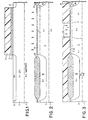
- Figures 1-11 are cross-sectional views in the fabrication sequence of the subject Bi-CMOS device.
- Referring now to Figure 1, onto a
P+ substrate 1 is deposited a P-epi layer 3. The starting wafer is a P- epi on a P+ substrate except if the PNP is to be isolated by N- epi on P+ substrate. The epi layer thickness is chosen so that, at the process end, the n+ subcollector junction depth is about 1 µm more shallow than the P-/P+ transition to avoid high capacitance/low voltage breakdown. This yields an epi layer thickness on the order of 3-6 µm. - Onto said
epi layer 3 is grown, approximately 250 Angström (10 Angström = 10Å = 1nm) ofoxide 5 followed by a deposition of approximately 1000 Angström of nitride 7. Aphotoresist mask layer 9 is then deposited over the nitride layer 7, wherein saidphotoresist layer 9 is exposed and developed in the selective areas 11 and 13. The nitride 7 andoxide 5 layers are now removed by RIE etching the unmasked areas.Subcollector areas - From Figure 2, it can be seen that the
subcollector areas thicknesses P layer 23. ThisP layer 23 helps block the lateral spread of the N+ subcollector during the subsequent epi growth (autodoping). - Referring now to Figure 3, a
photolithographic mask 25 is now deposited, exposed and developed to open a mask for the P+ subcollector reach-through 27 implant. TheP+ subcollector 27 is formed by implanting boron more heavily and deeply than the previous boron implant. The implant has a dose rate of approximately 10¹³-10¹⁵cm⁻ at 300-700 KEV range. Thissubcollector 27 also links the surface to the P+ substrate through a lower resistance path than the P-epi layer 3. The p+ subcollector and n+ subcollectors are prevented from coming into contact to avoid defect generation. TheP+ subcollector implant 27 also helps link the PNP collector to the substrate in the configuration wherein the subcollector is not isolated. The photoresist is stripped away and damage done by the ion implant is then removed by annealing on the order of 950_C for 30 minutes. - Both the thick and thin oxide layers 19, 21 and 5 are now removed from the surface of Figure 3 and an
epi layer 29 is grown approximately 0,9-1,5 µm thick. Theepi layer 29 can be doped to be either a P- or N- layer with approximately 1E10¹⁶ doping. With n- doping, theepi layer 29 will be as shown in Figure 4. As will be recognized by those skilled in the art, the implanted N+ and P+ profiles will diffuse into thenew epi layer 29 as shown. - Next, surface isolation is performed by using a type of a recessed-oxide isolation process. Referring now to Figure 5A, a
pad oxide 31 of 250 Angström is grown on the surface of the N-epi layer 29. Anitride layer 33 approximately 1000 Angström thick is deposited on thepad oxide 31 and a 5000Angström layer 35 of oxide is deposited by CVD over the nitride. This stack is then patterned and selectively removed by photolithography to form the isolation pattern desired. - Next, an "n well" mask 37 (where NPN and PFET are located) is used to open those areas in the isolation stack where the PFET and NPN will be made. A guard ring implant (10¹ -10¹³ dose) is made, with the selection of implant energies so that only the edges of the
device region guard ring 43 prevents leakage by enhancing the dopant concentration where the subsequent source/drain diffusions will butt the isolation oxide. With the "n well" resist 37 still in place, thetop CVD oxide 35 is removed (See Figure 5B) and the threshold adjust implant/punch-through protection implants are performed through thenitride 33 andpad oxide 31. In this process, a separate masking step to prevent the guard ring ion implant from influencing the threshold has been eliminated; in addition, the guard ring is self-aligned to the device area edge. The n-well resist 37 is then removed. - Figure 6 shows the forming of the P well for the NFET and PNP. Resist 45 covers the n-well regions and a p
type channel stop 47 is implanted into the field not doped by the n type guard ring but not into the nFET and PNP device regions. The purpose of the ptype channel stop 47 is to prevent inversion of the surface due to a charge in the oxide or from the gate overlap of the thick oxide. TheCVD oxide 35 on the p regions to be implanted is then selectively stripped away while leaving the P well resistmask 45 in place. Now, the P well/VT adjust implants are performed and the n- epi is locally converted intoP type 49A by these implants. The doping is such that during the field oxidation, the p well connects to the p type epi under the n-epi. The surface concentration is adjusted to attain the desired VT of the n FET. - Next, as seen in Figure 7A, the
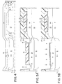
field 51 is oxidized (5000 Angström - 6000 Angström ), thenitride 33oxide 31 pad stack is removed and a gate oxide 53 (100 Angström - 150 Angström) is grown. The wafer is covered by a blanket deposition of a relatively thin (500 Angström - 600 Angström)layer 57 of LPCVD polysilicon. This layer acts to protect the gate oxide for the FET's while the oxide is removed for the formation of the bipolar transistors' emitters. - A resist
mask 59 is used for each type of bipolar device to define the area which will get the intrinsic base implant and the pedestal implant. First, thepolysilicon 57 is etched selectively down to the gate oxide 53 (by RIE, e.g.). Then, one type ofpedestal 61 is implanted (Figure 7A). Next, in order to avoid the emitter-base punch-through problem which might have arisen if the emitter edge were self-aligned to base edge, the resist 59 is controllably etched-back; in this way the subsequent intrinsic base implant goes under thepolysilicon layer 57 edge regions (and, therefore, past the emitter edge), to protect against punch-through as seen in Figure 7B. - The etch back can either be done in a resist strip tool or a more directional RIE tool run at relatively high pressure. The process needs some degree of lateral etch so that the edge of the resist pulls back laterally, allowing the intrinsic base implant to go under the polysilicon. This yields a higher base dopant concentration at the emitter edge. After the
intrinsic base implant 63, the resist 59 is stripped, and the analogous process (not shown) occurs on the opposite type of bipolar, with a mask to define the intrinsic base and pedestal implants. Again, the gate oxide acts as a screen oxide in both cases. - Now the polysilicon emitter and FET gate electrodes can be formed. Since for the bipolar, the polysilicon must be in contact with single crystal silicon, the
gate oxide 53 must be removed; but it must be kept for the FET's. As shown in Figure 8, this is resolved without a mask by using a dilute HF wet etch just prior to a second, thicker polysilicon deposition 65 (1500 Angström - 3000 Angström) to clean the surface. At the FET areas, however, theinitial polysilicon 57 covers the gates and prevents the etchant from damaging them. The etch clears off the surface of the polysilicon of any native oxide, so the next layer makes good contact to the previous polysilicon. Alternate masking 75 is now used to dope the polysilicon as appropriate foremitter gates gates - In Figure 9 to achieve a low resistivity, a silicide 77 (e.g., WSi₂ or TiSi₂) is formed on the
polysilicon 65 and a CVD oxide orintrinsic polysilicon 79 is used to cap thesilicide 77. The gate/emitter stacks 81, 83, 85, and 87 are then patterned by directional etching. - However, as the gate polysilicon is thicker than the emitter polysilicon (by the initial protective polysilicon 57) the single crystal silicon around the emitter will be etched. This will increase the distance between the emitter and the extrinsic base, so that the reverse breakdown voltage of the emitter-base junction will not be unacceptably low.
- Some combination of oxidation and CVD oxide deposition (along with RIE) is used to form a
spacer 91 approximately (300 Angström - 1000 Angström) at the edges of the emitter/gate. Thisoxide 91 acts as a spacer to offset the source/drain and extrinsic base implants from the edges of the gate/emitter. In the case of FET's, it prevents damage by the implants from impinging on the gate edge; for the bipolar, it moves the extrinsic base implant away from the emitter edge so the two high concentration regions do not touch and cause unacceptably low reverse breakdown. Two masks can now be used to selectively: 1) implant the p+ source/drain 93/95 andextrinsic base 97 of the pnp/pFET; and 2) implant the n+ source/drain 97/99 andextrinsic base 101 of the nFET/npn. If the spacing for the p+ to gate/emitter edge is to be different from the n+ to gate/emitter edge, one type implant can be done and then a second spacer formation process can be undertaken by CVD oxide deposition and RIE; this increases the source/drain (or extrinsic base) to gate/emitter edge spacing. Now the second source/drain implant can be done. - In Figure 11, the oxide and silicide on top of the gate/emitter polysilicon prevents the source/drain dopant from counter doping the polysilicon. A drive-in will finish the processing. The reach-through 103 to the N+ subcollector is made the same way as the npn
extrinsic base 97 adjacent to the emitter in that the reach-through gets a N+ implant using the source/drain mask. This N+ implant (instead of a P+ implant) counterdopes the base implant. Analogously, the reach-through to the P+ subcollector is made by using the non-emitter pnp base region doped with the p+ source/drain implant (not shown in Figure 11). No extra processing is needed to form the reach-through.
Claims (11)
- A process of simultaneous production of vertical NPN and PNP bipolar transistors and complementary field effect transistors on a common P-doped first epitaxial layer (3) grown on a semiconductor substrate (1), wherein in said epitaxial layer N+ subcollector areas (15, 17) are formed at selected locations; said subcollector areas are oxidized to a different height for alignment of subsequent masks and in said epitaxial layer, P+ subcollector areas (27) are also formed at selected locations for providing a low resistance path to the substrate, said process comprising the steps of:a) growing a second epitaxial layer (29) and growing/depositing a pad oxide (31) and nitride layer (33) on the surface of said second epitaxial layer (29) and depositing an oxide layer (35) onto said nitride layer;b) patterning said oxide/nitride/oxide layer to expose the surface isolation areas;c) defining n well regions with a mask (37) so that they contain a portion of second epitaxial layer (29) exposed during step b);d) implanting n type dopant at the exposed regions to form a device guard ring;e) removing said exposed oxide layer (35) and implanting n type dopant to adjust the threshold voltage;f) removing said n well mask (37) and repeating steps c) to e) for the p well regions for the n/FET and PNP substituting p-type dopant for the n-type dopant, and then removing the p well mask (45);g) oxidizing to form the field oxide (51), removing the nitride/pad oxide layer and growing a gate oxide layer (53);h) blanket depositing a layer (57) of LPCVD polysilicon;i) masking said polysilicon with a mask (59) and selectively etching said polysilicon down to the gate oxide in the bipolar emitter region and collector reach-through region;j) implanting an n-type pedestal collector in said opened locations;k) etching back the said mask (59);l) implanting P type dopant into the bipolar base well;m) removing the said mask (59);n) repeating steps g) to m) for the opposite type of bipolar device substituting p-type dopant for the n type dopant;o) partially removing the gate oxide layer (53);p) depositing a second layer (65) of polysilicon on the surface;q) doping said second polysilicon layer (65);r) patterning said second polysilicon layer (65) to form the gate electrodes and polysilicon emitter contacts whereby a recess is produced at the surface adjacent to the emitter contacts; and,s) forming the respective p type and n type reach-through, extrinsic base, and source and drain regions using photoresist masks and implanting the respective dopant in the predetermined regions.
- A process according to Claim 1 wherein said oxide/nitride/oxide layer are, respectively, approximately 25 nm, 100 nm and 500 nm thick.
- A process according to Claim 2 wherein said guard ring has a dopant concentration of 10⁻¹ to 10⁻¹³cm⁻.
- A process according to Claim 3 wherein the field is oxidized to a thickness of approximately 500-600 nm and the gate oxide is 10-15 thick, the blanket deposit of LPCVD polysilicon is 50-60 nm thick, the polysilicon is selectively etched by reactive ion etching, the polysilicon masking resist is etched backed either by a resist strip tool or directional RIE tool and wherein the gate oxide is removed by dilute hydrofluoric acid.
- A process according to Claim 4 wherein the second, thicker polysilicon deposition is 150-300 nm thick.
- A process according to Claim 5 wherein onto the second layer of polysilicon is located a layer of a silicide followed by a layer of CVD oxide, and the silicide is tungsten silicide or titanium silicide.
- A process according to Claim 6 wherein the gate electrode stacks and emitter electrode stacks are patterned by selective removal of the polysilicon, the removal being performed by reactive ion etching.
- A process according to Claim 7 wherein an oxide spacer layer is formed at the edges of the emitter contact and gate contact, this oxide layer being 30- 100 nm thick.
- A process according to Claim 8 wherein two ion implants are made to form the P+ source/drain and extrinsic base of the PNP/PFET and the n+ source/drain and extrinsic base of the nFET/NPN.
- A process according to Claim 8 wherein a second oxide spacer layer is formed at the edges of the emitter contact and gate contact which can then be followed by ion implants to form the source/drain and base regions.
- A process according to Claim 1 wherein the P+ subcollector is isolated from the substrate by an oxide formed by ion implanting oxygen, or by use of an N type epitaxial layer.
Applications Claiming Priority (2)
| Application Number | Priority Date | Filing Date | Title |
|---|---|---|---|
| US287945 | 1988-12-21 | ||
| US07/287,945 US4868135A (en) | 1988-12-21 | 1988-12-21 | Method for manufacturing a Bi-CMOS device |
Publications (3)
| Publication Number | Publication Date |
|---|---|
| EP0375585A2 EP0375585A2 (en) | 1990-06-27 |
| EP0375585A3 EP0375585A3 (en) | 1991-04-10 |
| EP0375585B1 true EP0375585B1 (en) | 1996-04-10 |
Family
ID=23105052
Family Applications (1)
| Application Number | Title | Priority Date | Filing Date |
|---|---|---|---|
| EP89480174A Expired - Lifetime EP0375585B1 (en) | 1988-12-21 | 1989-11-07 | Method for manufacturing a BI-CMOS device |
Country Status (4)
| Country | Link |
|---|---|
| US (1) | US4868135A (en) |
| EP (1) | EP0375585B1 (en) |
| JP (1) | JPH0744232B2 (en) |
| DE (1) | DE68926224T2 (en) |
Families Citing this family (56)
| Publication number | Priority date | Publication date | Assignee | Title |
|---|---|---|---|---|
| US4929565A (en) * | 1986-03-04 | 1990-05-29 | Motorola, Inc. | High/low doping profile for twin well process |
| US4897703A (en) * | 1988-01-29 | 1990-01-30 | Texas Instruments Incorporated | Recessed contact bipolar transistor and method |
| US5075241A (en) * | 1988-01-29 | 1991-12-24 | Texas Instruments Incorporated | Method of forming a recessed contact bipolar transistor and field effect device |
| JPH02101747A (en) * | 1988-10-11 | 1990-04-13 | Toshiba Corp | Semiconductor integrated circuit and manufacture thereof |
| US5028977A (en) * | 1989-06-16 | 1991-07-02 | Massachusetts Institute Of Technology | Merged bipolar and insulated gate transistors |
| EP0606114A1 (en) * | 1989-08-11 | 1994-07-13 | Seiko Instruments Inc. | Method of producing field effect transistor |
| EP0436297A3 (en) * | 1989-12-04 | 1992-06-17 | Raytheon Company | Small bicmos transistor |
| US4997775A (en) * | 1990-02-26 | 1991-03-05 | Cook Robert K | Method for forming a complementary bipolar transistor structure including a self-aligned vertical PNP transistor |
| US5102811A (en) * | 1990-03-20 | 1992-04-07 | Texas Instruments Incorporated | High voltage bipolar transistor in BiCMOS |
| US5104817A (en) * | 1990-03-20 | 1992-04-14 | Texas Instruments Incorporated | Method of forming bipolar transistor with integral base emitter load resistor |
| EP0452720A3 (en) * | 1990-04-02 | 1994-10-26 | Nat Semiconductor Corp | A semiconductor structure and method of its manufacture |
| JPH0445538A (en) * | 1990-06-13 | 1992-02-14 | Oki Electric Ind Co Ltd | Manufacture of semiconductor device |
| US5001073A (en) * | 1990-07-16 | 1991-03-19 | Sprague Electric Company | Method for making bipolar/CMOS IC with isolated vertical PNP |
| KR970000425B1 (en) * | 1990-09-20 | 1997-01-09 | 이해욱 | Bicmos type field effect transistor and manufacturing method thereof |
| KR940003589B1 (en) * | 1991-02-25 | 1994-04-25 | 삼성전자 주식회사 | Making method of bicmos device |
| EP0505877A2 (en) * | 1991-03-27 | 1992-09-30 | Seiko Instruments Inc. | Impurity doping method with adsorbed diffusion source |
| US5101257A (en) * | 1991-07-01 | 1992-03-31 | Motorola, Inc. | Semiconductor device having merged bipolar and MOS transistors and process for making the same |
| US5132236A (en) * | 1991-07-30 | 1992-07-21 | Micron Technology, Inc. | Method of semiconductor manufacture using an inverse self-aligned mask |
| KR940007466B1 (en) * | 1991-11-14 | 1994-08-18 | 삼성전자 주식회사 | Method of manufacturing bicmos device |
| US5306652A (en) * | 1991-12-30 | 1994-04-26 | Texas Instruments Incorporated | Lateral double diffused insulated gate field effect transistor fabrication process |
| WO1993016494A1 (en) * | 1992-01-31 | 1993-08-19 | Analog Devices, Inc. | Complementary bipolar polysilicon emitter devices |
| US5164326A (en) * | 1992-03-30 | 1992-11-17 | Motorola, Inc. | Complementary bipolar and CMOS on SOI |
| US5286991A (en) * | 1992-08-26 | 1994-02-15 | Pioneer Semiconductor Corporation | Capacitor for a BiCMOS device |
| US5504363A (en) * | 1992-09-02 | 1996-04-02 | Motorola Inc. | Semiconductor device |
| US5557131A (en) * | 1992-10-19 | 1996-09-17 | At&T Global Information Solutions Company | Elevated emitter for double poly BICMOS devices |
| US6011283A (en) * | 1992-10-19 | 2000-01-04 | Hyundai Electronics America | Pillar emitter for BiCMOS devices |
| US5384278A (en) * | 1992-11-16 | 1995-01-24 | United Technologies Corporation | Tight control of resistor valves in a SRAM process |
| US6249030B1 (en) * | 1992-12-07 | 2001-06-19 | Hyundai Electronics Industries Co., Ltd. | BI-CMOS integrated circuit |
| US5516718A (en) * | 1992-12-07 | 1996-05-14 | At&T Global Information Solutions Company | Method of making BI-CMOS integrated circuit having a polysilicon emitter |
| JP3343968B2 (en) * | 1992-12-14 | 2002-11-11 | ソニー株式会社 | Bipolar semiconductor device and method of manufacturing the same |
| US5411900A (en) * | 1993-03-05 | 1995-05-02 | Deutsche Itt Industries, Gmbh | Method of fabricating a monolithic integrated circuit with at least one CMOS field-effect transistor and one NPN bipolar transistor |
| DE4319437C1 (en) * | 1993-03-05 | 1994-05-19 | Itt Ind Gmbh Deutsche | BiCMOS monolithic IC mfr. - avoids need for epitaxial and buried layers |
| US5448085A (en) * | 1993-04-05 | 1995-09-05 | The United States Of America As Represented By The Secretary Of The Air Force | Limited current density field effect transistor with buried source and drain |
| US5441903A (en) * | 1993-12-03 | 1995-08-15 | Texas Instruments Incorporated | BiCMOS process for supporting merged devices |
| JPH07169771A (en) * | 1993-12-15 | 1995-07-04 | Nec Corp | Semiconductor device and its manufacture |
| US5444004A (en) * | 1994-04-13 | 1995-08-22 | Winbond Electronics Corporation | CMOS process compatible self-alignment lateral bipolar junction transistor |
| DE19523536A1 (en) * | 1994-07-12 | 1996-01-18 | Siemens Ag | CMOS FET and complementary bipolar transistor mfr. |
| JPH08107114A (en) * | 1994-10-04 | 1996-04-23 | Mitsubishi Electric Corp | Semiconductor device and manufacture thereof |
| US5449627A (en) * | 1994-12-14 | 1995-09-12 | United Microelectronics Corporation | Lateral bipolar transistor and FET compatible process for making it |
| US5627097A (en) * | 1995-07-03 | 1997-05-06 | Motorola, Inc. | Method for making CMOS device having reduced parasitic capacitance |
| JP2790084B2 (en) * | 1995-08-16 | 1998-08-27 | 日本電気株式会社 | Method for manufacturing semiconductor device |
| US5786622A (en) * | 1997-05-16 | 1998-07-28 | Tritech Microelectronics International Ltd. | Bipolar transistor with a ring emitter |
| US5882977A (en) * | 1997-10-03 | 1999-03-16 | International Business Machines Corporation | Method of forming a self-aligned, sub-minimum isolation ring |
| US6096618A (en) * | 1998-01-20 | 2000-08-01 | International Business Machines Corporation | Method of making a Schottky diode with sub-minimum guard ring |
| US6246096B1 (en) * | 1998-06-24 | 2001-06-12 | Advanced Micro Devices | Totally self-aligned transistor with tungsten gate |
| WO2003038893A2 (en) * | 2001-10-26 | 2003-05-08 | Infineon Technologies Ag | Semiconductor structure and method for the production thereof |
| US6762469B2 (en) * | 2002-04-19 | 2004-07-13 | International Business Machines Corporation | High performance CMOS device structure with mid-gap metal gate |
| US7037799B2 (en) * | 2002-10-24 | 2006-05-02 | Texas Instruments Incorporated | Breakdown voltage adjustment for bipolar transistors |
| US6909164B2 (en) * | 2002-11-25 | 2005-06-21 | International Business Machines Corporation | High performance vertical PNP transistor and method |
| JP4845410B2 (en) * | 2005-03-31 | 2011-12-28 | 株式会社リコー | Semiconductor device |
| JP4342579B2 (en) * | 2006-08-31 | 2009-10-14 | 三洋電機株式会社 | Semiconductor device |
| JP2009010341A (en) * | 2007-05-29 | 2009-01-15 | Toshiba Corp | Method of manufacturing semiconductor device |
| US8211786B2 (en) | 2008-02-28 | 2012-07-03 | International Business Machines Corporation | CMOS structure including non-planar hybrid orientation substrate with planar gate electrodes and method for fabrication |
| US7687862B2 (en) * | 2008-05-13 | 2010-03-30 | Infineon Technologies Ag | Semiconductor devices with active regions of different heights |
| CN103426759B (en) * | 2012-05-16 | 2016-02-10 | 上海华虹宏力半导体制造有限公司 | The manufacture method of PLDMOS |
| JP6219224B2 (en) * | 2014-04-21 | 2017-10-25 | ルネサスエレクトロニクス株式会社 | Semiconductor device |
Family Cites Families (7)
| Publication number | Priority date | Publication date | Assignee | Title |
|---|---|---|---|---|
| US4403395A (en) * | 1979-02-15 | 1983-09-13 | Texas Instruments Incorporated | Monolithic integration of logic, control and high voltage interface circuitry |
| US4637125A (en) * | 1983-09-22 | 1987-01-20 | Kabushiki Kaisha Toshiba | Method for making a semiconductor integrated device including bipolar transistor and CMOS transistor |
| US4553315A (en) * | 1984-04-05 | 1985-11-19 | Harris Corporation | N Contact compensation technique |
| US4696092A (en) * | 1984-07-02 | 1987-09-29 | Texas Instruments Incorporated | Method of making field-plate isolated CMOS devices |
| EP0239652B1 (en) * | 1986-03-22 | 1991-07-24 | Deutsche ITT Industries GmbH | Method of producing a monolithic integrated circuit with at least one bipolar planar transistor |
| JPS6329967A (en) * | 1986-07-24 | 1988-02-08 | Fuji Xerox Co Ltd | Manufacture of semiconductor device |
| US4784966A (en) * | 1987-06-02 | 1988-11-15 | Texas Instruments Incorporated | Self-aligned NPN bipolar transistor built in a double polysilicon CMOS technology |
-
1988
- 1988-12-21 US US07/287,945 patent/US4868135A/en not_active Expired - Fee Related
-
1989
- 1989-11-07 EP EP89480174A patent/EP0375585B1/en not_active Expired - Lifetime
- 1989-11-07 DE DE68926224T patent/DE68926224T2/en not_active Expired - Fee Related
- 1989-12-20 JP JP1328605A patent/JPH0744232B2/en not_active Expired - Lifetime
Also Published As
| Publication number | Publication date |
|---|---|
| EP0375585A3 (en) | 1991-04-10 |
| DE68926224T2 (en) | 1996-10-10 |
| EP0375585A2 (en) | 1990-06-27 |
| JPH02215158A (en) | 1990-08-28 |
| US4868135A (en) | 1989-09-19 |
| JPH0744232B2 (en) | 1995-05-15 |
| DE68926224D1 (en) | 1996-05-15 |
Similar Documents
| Publication | Publication Date | Title |
|---|---|---|
| EP0375585B1 (en) | Method for manufacturing a BI-CMOS device | |
| US6686233B2 (en) | Integration of high voltage self-aligned MOS components | |
| US5424572A (en) | Spacer formation in a semiconductor structure | |
| US7910425B2 (en) | Multiple doping level bipolar junctions transistors and method for forming | |
| US5428243A (en) | Bipolar transistor with a self-aligned heavily doped collector region and base link regions. | |
| US4962053A (en) | Bipolar transistor fabrication utilizing CMOS techniques | |
| US6271575B1 (en) | Method and mask structure for self-aligning ion implanting to form various device structures | |
| EP0768709B1 (en) | A BiCMOS process with low base recombination current bipolar transistor | |
| KR20010087183A (en) | Method of fabricating a polysilicon capacitor utilizing fet and bipolar base polysilicon layers | |
| US6461925B1 (en) | Method of manufacturing a heterojunction BiCMOS integrated circuit | |
| EP0281235B1 (en) | Bipolar transistor fabrication utilizing cmos techniques | |
| US5010034A (en) | CMOS and bipolar fabrication process using selective epitaxial growth scalable to below 0.5 micron | |
| US5504364A (en) | CMOS locos isolation for self-aligned NPN BJT in a BiCMOS process | |
| US5399509A (en) | Method of manufacturing a bipolar transistor | |
| US5065209A (en) | Bipolar transistor fabrication utilizing CMOS techniques | |
| US6790736B2 (en) | Method for manufacturing and structure of semiconductor device with polysilicon definition structure | |
| US6080612A (en) | Method of forming an ultra-thin SOI electrostatic discharge protection device | |
| EP0434182B1 (en) | Fabrication of buried layers in integrated circuits | |
| US6100124A (en) | Method for manufacturing a BiCMOS semiconductor device | |
| US6383855B1 (en) | High speed, low cost BICMOS process using profile engineering | |
| US6033232A (en) | Process of fabricating photodiode integrated with MOS device | |
| KR100259586B1 (en) | Method for manufacturing semiconductor device | |
| JP3247106B2 (en) | Manufacturing method and structure of integrated circuit | |
| JP2918205B2 (en) | Semiconductor device and manufacturing method thereof | |
| EP0366967B1 (en) | A method of forming integrated circuits having buried doped regions |
Legal Events
| Date | Code | Title | Description |
|---|---|---|---|
| PUAI | Public reference made under article 153(3) epc to a published international application that has entered the european phase |
Free format text: ORIGINAL CODE: 0009012 |
|
| AK | Designated contracting states |
Kind code of ref document: A2 Designated state(s): DE FR GB |
|
| 17P | Request for examination filed |
Effective date: 19901025 |
|
| PUAL | Search report despatched |
Free format text: ORIGINAL CODE: 0009013 |
|
| AK | Designated contracting states |
Kind code of ref document: A3 Designated state(s): DE FR GB |
|
| 17Q | First examination report despatched |
Effective date: 19930920 |
|
| GRAA | (expected) grant |
Free format text: ORIGINAL CODE: 0009210 |
|
| AK | Designated contracting states |
Kind code of ref document: B1 Designated state(s): DE FR GB |
|
| PG25 | Lapsed in a contracting state [announced via postgrant information from national office to epo] |
Ref country code: FR Effective date: 19960410 |
|
| REF | Corresponds to: |
Ref document number: 68926224 Country of ref document: DE Date of ref document: 19960515 |
|
| EN | Fr: translation not filed | ||
| PG25 | Lapsed in a contracting state [announced via postgrant information from national office to epo] |
Ref country code: GB Effective date: 19961107 |
|
| PLBE | No opposition filed within time limit |
Free format text: ORIGINAL CODE: 0009261 |
|
| STAA | Information on the status of an ep patent application or granted ep patent |
Free format text: STATUS: NO OPPOSITION FILED WITHIN TIME LIMIT |
|
| 26N | No opposition filed | ||
| GBPC | Gb: european patent ceased through non-payment of renewal fee |
Effective date: 19961107 |
|
| PG25 | Lapsed in a contracting state [announced via postgrant information from national office to epo] |
Ref country code: DE Effective date: 19970801 |