EP0375207B1 - Scroll apparatus control - Google Patents
Scroll apparatus control Download PDFInfo
- Publication number
- EP0375207B1 EP0375207B1 EP89312754A EP89312754A EP0375207B1 EP 0375207 B1 EP0375207 B1 EP 0375207B1 EP 89312754 A EP89312754 A EP 89312754A EP 89312754 A EP89312754 A EP 89312754A EP 0375207 B1 EP0375207 B1 EP 0375207B1
- Authority
- EP
- European Patent Office
- Prior art keywords
- pressure
- scroll
- machine
- control
- scroll machine
- Prior art date
- Legal status (The legal status is an assumption and is not a legal conclusion. Google has not performed a legal analysis and makes no representation as to the accuracy of the status listed.)
- Expired - Lifetime
Links
- 239000012530 fluid Substances 0.000 claims description 13
- 238000007599 discharging Methods 0.000 claims 1
- 239000003507 refrigerant Substances 0.000 description 12
- 230000006835 compression Effects 0.000 description 6
- 238000007906 compression Methods 0.000 description 6
- 230000001066 destructive effect Effects 0.000 description 3
- 230000003247 decreasing effect Effects 0.000 description 2
- 230000001050 lubricating effect Effects 0.000 description 2
- 238000004378 air conditioning Methods 0.000 description 1
- 238000010586 diagram Methods 0.000 description 1
- 238000009434 installation Methods 0.000 description 1
- 238000005057 refrigeration Methods 0.000 description 1
Images
Classifications
-
- F—MECHANICAL ENGINEERING; LIGHTING; HEATING; WEAPONS; BLASTING
- F04—POSITIVE - DISPLACEMENT MACHINES FOR LIQUIDS; PUMPS FOR LIQUIDS OR ELASTIC FLUIDS
- F04C—ROTARY-PISTON, OR OSCILLATING-PISTON, POSITIVE-DISPLACEMENT MACHINES FOR LIQUIDS; ROTARY-PISTON, OR OSCILLATING-PISTON, POSITIVE-DISPLACEMENT PUMPS
- F04C28/00—Control of, monitoring of, or safety arrangements for, pumps or pumping installations specially adapted for elastic fluids
- F04C28/06—Control of, monitoring of, or safety arrangements for, pumps or pumping installations specially adapted for elastic fluids specially adapted for stopping, starting, idling or no-load operation
-
- F—MECHANICAL ENGINEERING; LIGHTING; HEATING; WEAPONS; BLASTING
- F04—POSITIVE - DISPLACEMENT MACHINES FOR LIQUIDS; PUMPS FOR LIQUIDS OR ELASTIC FLUIDS
- F04C—ROTARY-PISTON, OR OSCILLATING-PISTON, POSITIVE-DISPLACEMENT MACHINES FOR LIQUIDS; ROTARY-PISTON, OR OSCILLATING-PISTON, POSITIVE-DISPLACEMENT PUMPS
- F04C2270/00—Control; Monitoring or safety arrangements
- F04C2270/70—Safety, emergency conditions or requirements
- F04C2270/72—Safety, emergency conditions or requirements preventing reverse rotation
-
- F—MECHANICAL ENGINEERING; LIGHTING; HEATING; WEAPONS; BLASTING
- F05—INDEXING SCHEMES RELATING TO ENGINES OR PUMPS IN VARIOUS SUBCLASSES OF CLASSES F01-F04
- F05B—INDEXING SCHEME RELATING TO WIND, SPRING, WEIGHT, INERTIA OR LIKE MOTORS, TO MACHINES OR ENGINES FOR LIQUIDS COVERED BY SUBCLASSES F03B, F03D AND F03G
- F05B2270/00—Control
- F05B2270/10—Purpose of the control system
- F05B2270/109—Purpose of the control system to prolong engine life
- F05B2270/1097—Purpose of the control system to prolong engine life by preventing reverse rotation
Definitions
- This invention relates generally to scroll compressors and more particularly to a control arrangement therefor for sensing low system gas charge and/or a reverse rotation condition.
- Scroll machines generally comprise first and second scroll members, each comprising an end plate which is provided with an upstanding spiral wrap.
- the scroll members are interleaved, with the flanks of the wraps engaging one another at substantially line contacts and the tips of each wrap sealingly engaging the end plate of the other scroll member so as to define travelling pockets of varying volume in which gas is compressed as one scroll member is caused to orbit relative to the other.
- Suction gas is communicated to the outermost compression chamber near the radially outward-most portion of the wraps and discharged through a discharge port centrally of the wraps.
- a motorized drive mechanism causes the orbiting scroll to orbit thereby decreasing the volume of the pockets and increasing the pressure of the compressed gas as it is progressively moved towards the discharge port.
- Exemplary of such an apparatus is US-A-4767293 entitled "Scroll Type Machine", the disclosure thereof being specifically incorporated herein by reference.
- the pockets are pressurized thereby causing the scroll members to be forced apart, however when orbited in the reverse direction the machine acts as a vacuum pump and therefore the scroll members are drawn together.
- the latter can be caused when the motor is improperly wired, or by a power interrupt, and the resulting vacuum can cause damage to the scroll members because of the excessive wear which occurs.
- the possibly destructive vacuum condition can also occur when a serviceman runs the compressor with the suction blocked, a not uncommon occurrence.
- Another condition which can result in excessive wear is a loss of charge particularly in a refrigerant compressor, which results from the installation of insufficient refrigerant into the system or from refrigerant leakage.
- US-A-4672231 discloses a pressure sensing and control apparatus for use in connection with a piston type refrigerant compressor.
- the apparatus senses whether or not sufficient lubricating pressure exists by sensing the difference in pressure between the output of an oil pump and the crankcase of the compressor.
- the apparatus is arranged to deenergize the compressor motor when the lubricating pressure is insufficient, to prevent undue wear and possible seizure of the compressor.
- the apparatus is however not sensitive to a possibly destructive vacuum condition of the type described above in relation to scroll-type machines.
- a scroll machine comprising:
- a hermetic scroll compressor 10 comprises a shell (not shown) for enclosing a driving electric motor 12 connected by a crankshaft (not shown) to a scroll assembly 14 comprising a pair of interleaved scroll members 16 and 18 including end plates 17 and 19 having respective spiral wraps 20 and 22 projecting therefrom.
- scroll members 16 and 18 are, respectively, non-orbiting and orbiting.
- the scroll members receive refrigerant gas at radially outward suction inlets 24 and discharge the refrigerant through a discharge port 26 in end plate 17.
- the crankshaft is operative to drive one of the scroll members in an orbit relative to the other scroll member, i.e.
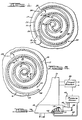
- Figure 1 shows a position wherein outward radial tip 32 at the end of the non-orbiting scroll wrap 20 has just sealed a compression chamber 33 which extends around to approximately point A .
- a similar outward radial tip 34 at the end of wrap 22 has just sealed against wrap 20.
- Figure 2 shows the scroll assembly 180° crank angle later wherein the inner tip 36 of orbiting scroll wrap 22 is ready to separate from wrap 20 and place the fluid in compression chamber 31 in communication with discharge opening 26, the beginning of chamber 31 being indicated at point B .
- the outward radial tips 32 and 34 allow a new charge of refrigerant to be received in compressor assembly 14. Further orbiting of scroll member 18 will cause continuing discharge in the usual manner.
- a unique arrangement is provided for sensing an internal chamber pressure in scroll machine and, depending on the application, disabling the driving motor so that the compressor cannot be operated if the pressure indication is above or below a predetermined value.
- either absolute chamber pressure or the differential between the chamber pressure and suction pressure can be sensed.
- a pressure sensing port 40 is located in end plate 17 in a position to sense the pressure in chamber 30.
- Port 40 is preferably located just inwardly of point A because that is where the maximum vacuum will be developed in a reverse rotation situation, and yet is a point which will never see suction pressure.
- Port 40 can be located further angularly inwardly if desired, such as to increase response time, but cannot be located further inwardly than point B because it should never see discharge pressure.
- the port is located in the range between approximately 10° inwardly of point A and approximately 10° outwardly of point B . This places the port in a range slightly more than 360° from the inner and outer ends of wrap 20.
- An electrical output pressure sensor 42 is provided which, depending on the application, is responsive to the absolute pressure in chamber 30 via a tube 43 and fitting 44, connected to end plate 17 in fluid communication with port 40; or to the differential pressure between port 40 and suction pressure via a tube 46 in communication suction line 48 (for example).
- a line circuit breaker 50 is electrically connected to motor 12 and receives a signal, from the pressure sensor 42. Should the signal be of a value indicating that the pressure in chamber 30 is below a predetermined value, then the circuit breaker will act to disable the electrical connection to motor 12.
- the compressor If during compressor operation the absolute pressure of pocket 30 goes below a predetermined value (determined by the application), then the compressor is either running backwards or the system is low on refrigerant charge. If the measured pressure is lower than suction pressure during compressor operation, then the compressor is running backwards.
- the predetermined value is a matter of choice, but is preferably less than the minimum pressure normally encountered under design operating conditions.
Landscapes
- Engineering & Computer Science (AREA)
- Mechanical Engineering (AREA)
- General Engineering & Computer Science (AREA)
- Rotary Pumps (AREA)
- Applications Or Details Of Rotary Compressors (AREA)
- Heat-Exchange Devices With Radiators And Conduit Assemblies (AREA)
- Structures Of Non-Positive Displacement Pumps (AREA)
Description
- This invention relates generally to scroll compressors and more particularly to a control arrangement therefor for sensing low system gas charge and/or a reverse rotation condition.
- Scroll machines generally comprise first and second scroll members, each comprising an end plate which is provided with an upstanding spiral wrap. The scroll members are interleaved, with the flanks of the wraps engaging one another at substantially line contacts and the tips of each wrap sealingly engaging the end plate of the other scroll member so as to define travelling pockets of varying volume in which gas is compressed as one scroll member is caused to orbit relative to the other. Suction gas is communicated to the outermost compression chamber near the radially outward-most portion of the wraps and discharged through a discharge port centrally of the wraps. A motorized drive mechanism causes the orbiting scroll to orbit thereby decreasing the volume of the pockets and increasing the pressure of the compressed gas as it is progressively moved towards the discharge port. Exemplary of such an apparatus is US-A-4767293 entitled "Scroll Type Machine", the disclosure thereof being specifically incorporated herein by reference.
- When a scroll machine works as a compressor, the pockets are pressurized thereby causing the scroll members to be forced apart, however when orbited in the reverse direction the machine acts as a vacuum pump and therefore the scroll members are drawn together. The latter can be caused when the motor is improperly wired, or by a power interrupt, and the resulting vacuum can cause damage to the scroll members because of the excessive wear which occurs. The possibly destructive vacuum condition can also occur when a serviceman runs the compressor with the suction blocked, a not uncommon occurrence.
- Another condition which can result in excessive wear is a loss of charge particularly in a refrigerant compressor, which results from the installation of insufficient refrigerant into the system or from refrigerant leakage.
- US-A-4672231 discloses a pressure sensing and control apparatus for use in connection with a piston type refrigerant compressor. The apparatus senses whether or not sufficient lubricating pressure exists by sensing the difference in pressure between the output of an oil pump and the crankcase of the compressor. The apparatus is arranged to deenergize the compressor motor when the lubricating pressure is insufficient, to prevent undue wear and possible seizure of the compressor. The apparatus is however not sensitive to a possibly destructive vacuum condition of the type described above in relation to scroll-type machines.
- According to the present invention there is provided a scroll machine comprising:
- (a) a scroll assembly comprising a pair of scroll members, each including an end plate and an upstanding spiral wrap, said spiral wraps intermeshing with one another so as to define a plurality of pockets whereby orbiting of one scroll member with respect to the other scroll member will cause said pockets to progressively change in volume;
- (b) means defining an inlet chamber for supplying inlet fluid to said scroll assembly;
- (c) drive means for causing one of said scroll members to orbit with respect to the other scroll member; and
- (d) control means responsive to a control pressure for deenergizing said drive means when said pressure is of a value indicating an undesirable machine condition, said control pressure being the pressure of fluid in one of said pockets.
- There is thus provided a scroll machine with a control means which is capable of overcoming the problems of continued running of the machine in the above-mentioned possibly destructive vacuum condition. Furthermore, the control is both simple and inexpensive and does not result in a significant loss of machine efficiency.
- An embodiment of the invention will now be described, by way of example, with reference to the accompanying drawings, in which:
- Figures 1 and 2 are schematic horizontal cross-sectional views of a portion of a scroll compressor assembly including a pair of intermeshed scroll members, illustrated at two different stages of compression, the view being taken from the middle of the assembly and looking toward the non-orbiting scroll member; and
- Figure 3 shows a schematic diagram of a control arrangement which can be used in conjunction with the sensing means of the present invention in order to deenergize the compressor when there is a loss of refrigerant charge or a vacuum is being generated.
- Although the principles of the present invention may be applied to many different types of scroll machine, they are described herein for exemplary purposes embodied in a hermetic scroll-type compressor, and particularly one which has been found to have specific utility in the compression of refrigerant for air conditioning, heat pump and/or refrigeration systems.
- A hermetic scroll compressor 10 comprises a shell (not shown) for enclosing a driving
electric motor 12 connected by a crankshaft (not shown) to ascroll assembly 14 comprising a pair ofinterleaved scroll members end plates 17 and 19 having respectivespiral wraps members outward suction inlets 24 and discharge the refrigerant through a discharge port 26 inend plate 17. The crankshaft is operative to drive one of the scroll members in an orbit relative to the other scroll member, i.e. orbitingscroll member 18, such that the wraps define a plurality of sealed compression pockets or chambers, such aspockets 30 and 31, which travel along a spiralling path generally radially inwardly while the volume of the pocket is progressively decreased, thereby compressing the fluid therein. A compressor of this type, to which the invention is applicable is fully disclosed in assignee's aforementioned patent. Except for the sensing means of the present invention the scroll machine is in all ways of known design and operation. - Figure 1 shows a position wherein outward
radial tip 32 at the end of thenon-orbiting scroll wrap 20 has just sealed a compression chamber 33 which extends around to approximately point A. A similar outward radial tip 34 at the end ofwrap 22 has just sealed againstwrap 20. Figure 2 shows the scroll assembly 180° crank angle later wherein theinner tip 36 of orbitingscroll wrap 22 is ready to separate fromwrap 20 and place the fluid in compression chamber 31 in communication with discharge opening 26, the beginning of chamber 31 being indicated at point B. The outwardradial tips 32 and 34 allow a new charge of refrigerant to be received incompressor assembly 14. Further orbiting ofscroll member 18 will cause continuing discharge in the usual manner. - In accordance with this invention, a unique arrangement is provided for sensing an internal chamber pressure in scroll machine and, depending on the application, disabling the driving motor so that the compressor cannot be operated if the pressure indication is above or below a predetermined value. In this regard, either absolute chamber pressure or the differential between the chamber pressure and suction pressure can be sensed.
- Referring to the drawings, a pressure sensing port 40 is located in
end plate 17 in a position to sense the pressure inchamber 30. Port 40 is preferably located just inwardly of point A because that is where the maximum vacuum will be developed in a reverse rotation situation, and yet is a point which will never see suction pressure. Port 40 can be located further angularly inwardly if desired, such as to increase response time, but cannot be located further inwardly than point B because it should never see discharge pressure. Preferably the port is located in the range between approximately 10° inwardly of point A and approximately 10° outwardly of point B. This places the port in a range slightly more than 360° from the inner and outer ends ofwrap 20. - An electrical output pressure sensor 42 is provided which, depending on the application, is responsive to the absolute pressure in
chamber 30 via a tube 43 and fitting 44, connected toend plate 17 in fluid communication with port 40; or to the differential pressure between port 40 and suction pressure via atube 46 in communication suction line 48 (for example). Aline circuit breaker 50 is electrically connected tomotor 12 and receives a signal, from the pressure sensor 42. Should the signal be of a value indicating that the pressure inchamber 30 is below a predetermined value, then the circuit breaker will act to disable the electrical connection tomotor 12. - If during compressor operation the absolute pressure of
pocket 30 goes below a predetermined value (determined by the application), then the compressor is either running backwards or the system is low on refrigerant charge. If the measured pressure is lower than suction pressure during compressor operation, then the compressor is running backwards. The predetermined value is a matter of choice, but is preferably less than the minimum pressure normally encountered under design operating conditions. - In the case of the compressor running backwards, the normal discharge valve or discharge flow check valve on the scroll machine will prevent backflow into the compressor as refrigerant in the pockets is forced out through the normal suction openings of the compressor due to reverse rotation. As a result, the internal volume of the compressor between point A on the wrap and the discharge check valve will be quickly evacuated to a very low pressure, certainly a pressure below suction pressure and also below any pressure the system would normally experience. Thus, an abnormally low chamber pressure can be used to detect reverse rotation of the compressor.
- With regard to sensing low charge in the system (i.e., inadequate refrigerant being supplied by
inlet 24 to the scroll assembly), a low system charge will result in abnormally low suction pressure during compressor operation. Compressing an abnormally low suction pressure results in an abnormally low pressure inchamber 30. Thus, sensing a chamber pressure below some preset value which is below a normally expected pressure level in the chamber would indicate a low system charge.
Claims (17)
- A scroll machine, comprising:(a) a scroll assembly (14) comprising a pair of scroll members (16, 18), each including an end plate (17, 19) and an upstanding spiral wrap (20, 22), said spiral wraps intermeshing with one another so as to define a plurality of pockets (30, 31) whereby orbiting of one scroll member with respect to the other scroll member will cause said pockets to progressively change in volume;(b) means defining an inlet chamber (24) for supplying inlet fluid to said scroll assembly; and(c) drive means (12) for causing one of said scroll members to orbit with respect to the other scroll member;
characterised in that the machine further comprises:(d) control means (40, 42, 50) responsive to a control pressure for deenergizing said drive means when said pressure is of a value indicating an undesirable machine condition, said control pressure being the pressure of fluid in one of said pockets. - A scroll machine as claimed in claim 1, wherein said control pressure is sensed at a point (40) on a scroll member which is more than 360 degrees from the outer end of the wrap (20) which defines the outside of said one of said pockets (30).
- A scroll machine as claimed in claim 1 or claim 2, wherein said control pressure is sensed at a point (40) which never sees inlet pressure.
- A scroll machine as claimed in any of the preceding claims, further comprising means defining an outlet port (26) for discharging fluid from said machine, where said control pressure is sensed at a point (40) which never sees discharged fluid at outlet pressure.
- A scroll machine as claimed in any of the preceding claims, wherein each said pocket (30, 31) moves from a first open condition in which it receives inlet fluid to a closed condition in which the pressure of the fluid therein changes with pocket volume, and then to a second open condition in which fluid is discharged.
- A scroll machine as claimed in claim 5, wherein said control pressure is sensed at a point (40) in said pocket just after said pocket closes.
- A scroll machine as claimed in claim 6, wherein said point (40) is approximately 10 degrees after said pocket closes.
- A scroll machine as claimed in claim 5, wherein said control pressure is sensed at a point (40) in said pocket just before said pocket opens to said second open condition.
- A scroll machine as claimed in claim 8, wherein said point (40) is approximately 10 degrees before said pocket opens.
- A scroll machine as claimed in any of the preceding claims, wherein said control means (40, 42, 50) is arranged to deenergize said drive means (12) when said control pressure drops below a predetermined value.
- A scroll machine as claimed in claim 10, wherein said predetermined value is slightly less than the minimum pressure expected in said one of said pockets under normal operating conditions.
- A scroll machine as claimed in any of claims 1 to 9, wherein said control means (40, 42, 50) also senses inlet pressure, said control pressure being the pressure differential between the pressure of fluid in said one of said pockets and said inlet pressure.
- A scroll machine as claimed in claim 12, wherein said control means (40, 42, 50) is arranged to deenergize said drive means (12) when said control pressure is slightly less than the minimum pressure differential expected under normal operating conditions.
- A scroll machine as claimed in claim 12, wherein said control means (40, 42, 50) is arranged to deenergize said drive means when said control pressure is approximately zero pressure differential.
- A scroll machine as claimed in any of claims 1 to 9, wherein said control pressure is slightly less than the minimum pressure expected in said one of said pockets under normal operating conditions.
- A scroll machine as claimed in any of claims 1 to 9, wherein said machine is a gas compressor and said control means (40, 42, 50) is arranged to deenergize said drive means (12) when said compressor is generating a vacuum.
- A scroll machine as claimed in any of claims 1 to 9, wherein said machine is a gas compressor adapted to be used in a closed system and said control means (40, 42, 50) is arranged to deenergize said drive means (12) when there is a loss of system gas charge.
Applications Claiming Priority (2)
| Application Number | Priority Date | Filing Date | Title |
|---|---|---|---|
| US07/287,912 US4955795A (en) | 1988-12-21 | 1988-12-21 | Scroll apparatus control |
| US287912 | 1988-12-21 |
Publications (3)
| Publication Number | Publication Date |
|---|---|
| EP0375207A2 EP0375207A2 (en) | 1990-06-27 |
| EP0375207A3 EP0375207A3 (en) | 1990-12-27 |
| EP0375207B1 true EP0375207B1 (en) | 1994-01-26 |
Family
ID=23104901
Family Applications (1)
| Application Number | Title | Priority Date | Filing Date |
|---|---|---|---|
| EP89312754A Expired - Lifetime EP0375207B1 (en) | 1988-12-21 | 1989-12-07 | Scroll apparatus control |
Country Status (6)
| Country | Link |
|---|---|
| US (1) | US4955795A (en) |
| EP (1) | EP0375207B1 (en) |
| JP (1) | JP2696256B2 (en) |
| KR (1) | KR0171573B1 (en) |
| DE (1) | DE68912749T2 (en) |
| ES (1) | ES2043573T3 (en) |
Cited By (1)
| Publication number | Priority date | Publication date | Assignee | Title |
|---|---|---|---|---|
| US7861541B2 (en) | 2004-07-13 | 2011-01-04 | Tiax Llc | System and method of refrigeration |
Families Citing this family (14)
| Publication number | Priority date | Publication date | Assignee | Title |
|---|---|---|---|---|
| US5200872A (en) * | 1989-12-08 | 1993-04-06 | Texas Instruments Incorporated | Internal protection circuit for electrically driven device |
| US5110323A (en) * | 1990-01-04 | 1992-05-05 | Stone & Webster Engineering Corp. | Process for the return of recovered particulate solids by a cyclone separator to a vessel |
| US5141407A (en) * | 1990-10-01 | 1992-08-25 | Copeland Corporation | Scroll machine with overheating protection |
| US5186613A (en) * | 1991-12-20 | 1993-02-16 | American Standard Inc. | Reverse phase and high discharge temperature protection in a scroll compressor |
| US5368446A (en) * | 1993-01-22 | 1994-11-29 | Copeland Corporation | Scroll compressor having high temperature control |
| JPH09121590A (en) * | 1995-09-14 | 1997-05-06 | Copeland Corp | Rotary compressor provided with counter-current braking mechanism |
| US5772403A (en) * | 1996-03-27 | 1998-06-30 | Butterworth Jetting Systems, Inc. | Programmable pump monitoring and shutdown system |
| US6679683B2 (en) * | 2000-10-16 | 2004-01-20 | Copeland Corporation | Dual volume-ratio scroll machine |
| US6491500B1 (en) * | 2000-10-31 | 2002-12-10 | Scroll Technologies | Scroll compressor with motor protector in non-orbiting scroll and flow enhancement |
| US6893227B2 (en) * | 2002-03-21 | 2005-05-17 | Kendro Laboratory Products, Inc. | Device for prevention of backward operation of scroll compressors |
| US20040193330A1 (en) * | 2003-03-26 | 2004-09-30 | Ingersoll-Rand Company | Method and system for controlling compressors |
| US20040189590A1 (en) * | 2003-03-26 | 2004-09-30 | Ingersoll-Rand Company | Human machine interface for a compressor system |
| US7654804B2 (en) * | 2008-01-08 | 2010-02-02 | Chu Henry C | Fluid displacement apparatus having pressure sensing device |
| EP3775723A1 (en) | 2018-04-09 | 2021-02-17 | Carrier Corporation | Reverse rotation prevention in centrifugal compressor |
Family Cites Families (6)
| Publication number | Priority date | Publication date | Assignee | Title |
|---|---|---|---|---|
| JPS56580A (en) * | 1979-06-12 | 1981-01-07 | Tokico Ltd | Oil-cooled compressor |
| US4551069A (en) * | 1984-03-14 | 1985-11-05 | Copeland Corporation | Integral oil pressure sensor |
| KR890000052B1 (en) * | 1985-05-16 | 1989-03-06 | 미쓰비시전기 주식회사 | Scroll-type fluid transfering machine with intake port and second intake passage |
| US4672231A (en) * | 1986-01-14 | 1987-06-09 | Texas Instruments Incorporated | Control circuit particularly adapted for use with lubrication sensor apparatus |
| US4767293A (en) * | 1986-08-22 | 1988-08-30 | Copeland Corporation | Scroll-type machine with axially compliant mounting |
| US5047845A (en) * | 1990-10-09 | 1991-09-10 | General Electric Company | Charge-transfer-device planar array for detecting coherent-light phase |
-
1988
- 1988-12-21 US US07/287,912 patent/US4955795A/en not_active Expired - Lifetime
-
1989
- 1989-12-07 EP EP89312754A patent/EP0375207B1/en not_active Expired - Lifetime
- 1989-12-07 ES ES89312754T patent/ES2043573T3/en not_active Expired - Lifetime
- 1989-12-07 DE DE89312754T patent/DE68912749T2/en not_active Expired - Fee Related
- 1989-12-12 JP JP1322446A patent/JP2696256B2/en not_active Expired - Fee Related
- 1989-12-20 KR KR1019890019357A patent/KR0171573B1/en not_active IP Right Cessation
Cited By (1)
| Publication number | Priority date | Publication date | Assignee | Title |
|---|---|---|---|---|
| US7861541B2 (en) | 2004-07-13 | 2011-01-04 | Tiax Llc | System and method of refrigeration |
Also Published As
| Publication number | Publication date |
|---|---|
| US4955795A (en) | 1990-09-11 |
| ES2043573T3 (en) | 1994-03-16 |
| ES2043573T1 (en) | 1994-01-01 |
| EP0375207A2 (en) | 1990-06-27 |
| DE68912749D1 (en) | 1994-03-10 |
| EP0375207A3 (en) | 1990-12-27 |
| JP2696256B2 (en) | 1998-01-14 |
| KR0171573B1 (en) | 1999-03-20 |
| KR900010235A (en) | 1990-07-06 |
| JPH02196183A (en) | 1990-08-02 |
| DE68912749T2 (en) | 1994-05-11 |
Similar Documents
| Publication | Publication Date | Title |
|---|---|---|
| EP0375207B1 (en) | Scroll apparatus control | |
| CA1172221A (en) | Gas compressor of the scroll type having delayed suction closing capacity modulation | |
| EP1496258B1 (en) | Hermetic compressors | |
| EP1493980B1 (en) | Compressor diagnostic system | |
| US6095765A (en) | Combined pressure ratio and pressure differential relief valve | |
| US7201567B2 (en) | Plural compressors | |
| US20040187502A1 (en) | Compressor diagnostic system | |
| EP0840011B1 (en) | Scroll machine with reverse rotation sound attenuation | |
| EP1158166B1 (en) | Scroll type compressor | |
| US6398507B1 (en) | Overheat protection device for scroll compressor | |
| US20040115063A1 (en) | Scroll compressor | |
| US6418740B1 (en) | External high pressure to low pressure valve for scroll compressor | |
| KR100332780B1 (en) | Apparatus for preventing superheating of low pressure type scroll compressor | |
| KR100438957B1 (en) | Over load protector of scroll compressor | |
| KR20000040738A (en) | Device for preventing damage of scroll compressor |
Legal Events
| Date | Code | Title | Description |
|---|---|---|---|
| PUAI | Public reference made under article 153(3) epc to a published international application that has entered the european phase |
Free format text: ORIGINAL CODE: 0009012 |
|
| AK | Designated contracting states |
Kind code of ref document: A2 Designated state(s): DE ES FR GB IT |
|
| PUAL | Search report despatched |
Free format text: ORIGINAL CODE: 0009013 |
|
| AK | Designated contracting states |
Kind code of ref document: A3 Designated state(s): DE ES FR GB IT |
|
| 17P | Request for examination filed |
Effective date: 19910412 |
|
| 17Q | First examination report despatched |
Effective date: 19920429 |
|
| GRAA | (expected) grant |
Free format text: ORIGINAL CODE: 0009210 |
|
| AK | Designated contracting states |
Kind code of ref document: B1 Designated state(s): DE ES FR GB IT |
|
| REF | Corresponds to: |
Ref document number: 68912749 Country of ref document: DE Date of ref document: 19940310 |
|
| REG | Reference to a national code |
Ref country code: ES Ref legal event code: FG2A Ref document number: 2043573 Country of ref document: ES Kind code of ref document: T3 |
|
| ET | Fr: translation filed | ||
| ITF | It: translation for a ep patent filed |
Owner name: PROPRIA PROT. PROPRIETA' IND. |
|
| PLBE | No opposition filed within time limit |
Free format text: ORIGINAL CODE: 0009261 |
|
| STAA | Information on the status of an ep patent application or granted ep patent |
Free format text: STATUS: NO OPPOSITION FILED WITHIN TIME LIMIT |
|
| 26N | No opposition filed | ||
| REG | Reference to a national code |
Ref country code: GB Ref legal event code: IF02 |
|
| PGFP | Annual fee paid to national office [announced via postgrant information from national office to epo] |
Ref country code: FR Payment date: 20021111 Year of fee payment: 14 |
|
| PGFP | Annual fee paid to national office [announced via postgrant information from national office to epo] |
Ref country code: GB Payment date: 20021115 Year of fee payment: 14 |
|
| PGFP | Annual fee paid to national office [announced via postgrant information from national office to epo] |
Ref country code: DE Payment date: 20021119 Year of fee payment: 14 |
|
| PGFP | Annual fee paid to national office [announced via postgrant information from national office to epo] |
Ref country code: ES Payment date: 20021210 Year of fee payment: 14 |
|
| PG25 | Lapsed in a contracting state [announced via postgrant information from national office to epo] |
Ref country code: GB Free format text: LAPSE BECAUSE OF NON-PAYMENT OF DUE FEES Effective date: 20031207 |
|
| PG25 | Lapsed in a contracting state [announced via postgrant information from national office to epo] |
Ref country code: ES Free format text: LAPSE BECAUSE OF NON-PAYMENT OF DUE FEES Effective date: 20031209 |
|
| PG25 | Lapsed in a contracting state [announced via postgrant information from national office to epo] |
Ref country code: DE Free format text: LAPSE BECAUSE OF NON-PAYMENT OF DUE FEES Effective date: 20040701 |
|
| GBPC | Gb: european patent ceased through non-payment of renewal fee |
Effective date: 20031207 |
|
| PG25 | Lapsed in a contracting state [announced via postgrant information from national office to epo] |
Ref country code: FR Free format text: LAPSE BECAUSE OF NON-PAYMENT OF DUE FEES Effective date: 20040831 |
|
| REG | Reference to a national code |
Ref country code: FR Ref legal event code: ST |
|
| REG | Reference to a national code |
Ref country code: ES Ref legal event code: FD2A Effective date: 20031209 |
|
| PG25 | Lapsed in a contracting state [announced via postgrant information from national office to epo] |
Ref country code: IT Free format text: LAPSE BECAUSE OF NON-PAYMENT OF DUE FEES;WARNING: LAPSES OF ITALIAN PATENTS WITH EFFECTIVE DATE BEFORE 2007 MAY HAVE OCCURRED AT ANY TIME BEFORE 2007. THE CORRECT EFFECTIVE DATE MAY BE DIFFERENT FROM THE ONE RECORDED. Effective date: 20051207 |