EP0375015A2 - Method and device for adaptive digital cancellation of the echo generated in telephone connections with time-variant characteristics - Google Patents
Method and device for adaptive digital cancellation of the echo generated in telephone connections with time-variant characteristics Download PDFInfo
- Publication number
- EP0375015A2 EP0375015A2 EP89203107A EP89203107A EP0375015A2 EP 0375015 A2 EP0375015 A2 EP 0375015A2 EP 89203107 A EP89203107 A EP 89203107A EP 89203107 A EP89203107 A EP 89203107A EP 0375015 A2 EP0375015 A2 EP 0375015A2
- Authority
- EP
- European Patent Office
- Prior art keywords
- echo
- signal
- vector
- adaptive
- coefficients
- Prior art date
- Legal status (The legal status is an assumption and is not a legal conclusion. Google has not performed a legal analysis and makes no representation as to the accuracy of the status listed.)
- Granted
Links
Images


Classifications
-
- H—ELECTRICITY
- H04—ELECTRIC COMMUNICATION TECHNIQUE
- H04B—TRANSMISSION
- H04B3/00—Line transmission systems
- H04B3/02—Details
- H04B3/20—Reducing echo effects or singing; Opening or closing transmitting path; Conditioning for transmission in one direction or the other
- H04B3/23—Reducing echo effects or singing; Opening or closing transmitting path; Conditioning for transmission in one direction or the other using a replica of transmitted signal in the time domain, e.g. echo cancellers
- H04B3/234—Reducing echo effects or singing; Opening or closing transmitting path; Conditioning for transmission in one direction or the other using a replica of transmitted signal in the time domain, e.g. echo cancellers using double talk detection
Landscapes
- Engineering & Computer Science (AREA)
- Computer Networks & Wireless Communication (AREA)
- Signal Processing (AREA)
- Cable Transmission Systems, Equalization Of Radio And Reduction Of Echo (AREA)
- Telephone Function (AREA)
Abstract
Description
- The present invention relates to the field of signal transmission on telephone lines and in particular to a procedure and device for adaptive digital cancellation of the echo generated in telephone connections with time-variant characteristics.
- It is known that telephone signals travel on lines which can be considered 1-way or 2-way telephone lines depending on the direction of travel thereof.
- 2-way lines, also called 2-wire lines, are generally used locally, mainly for the connection of telephone sets to the associated exchange.
- 1-Way lines, also called 4-wire lines regardless of the physical nature of the medium supporting them, are used generally for connections between telephone exchanges placed even at a considerable distance apart. In this case the connection can include sections by cable and/or radio link and either terrestrial or satellite.
- As is known the coupling between a 2-way line and the corresponding 1-way lines for transmission and reception respectively is activated by the so-called hybrid coil.
- For a connection to be complete it must include at least two hybrid coils. Each one accomplishes conversion from 2-wire line to 4-wire line and the reverse.
- It is known that the hybrid coil has four ports, one connected to the 2-way line which costitutes the telephone pair, a second port connected to the 1-way transmission line, a third port connected to the 1-way reception line and a fourth port connected to a so-called balancing impedance.
- Operation of the hybrid coil can be understood by examining the specific case in which for all the frequencies included in the voice band the impedance it presents at its ports is equal to that of the load connected to the respective ports. In this case the power present on the telephone pair is divided exactly in half between the 1-way transmission line and the balancing impedance. Similarly and independently the power present on the 1-way reception line is divided exactly in half between the telephone pair and the balancing impedance to allow separation of the transmitted signals from those received.
- However this case is purely ideal. in practice coupling to the various ports of the hybrid coil is never perfect and the ensuing unbalancing causes signal reflection between them.
- In particular part of the voice signal present at the reception port of the hybrid coil and coming from the far-end talker is transferred to the transmission port and thence back to the same talker who, while he is still talking, listens to what he said with delay equal to the time taken by the voice signal to complete the path from the remote hybrid coil and return.
- The signal fraction played back is the echo of the signal transmitted and the path the echo completes from the point of generation to the point of listening is called 'echo channel'.
- It has been proven that the effects of the echo are annoying for delays over a few tens of milliseconds and echo channel attenuations between 6dB and 15dB if appropriate corrective devices such as the so-called 'echo cancellers' are not adopted. These devices are usually inserted in 4-wire lines connected to an international exchange and blank the echo produced during the conversation by subtracting from the actual echo signal an estimate thereof.
- Causes of unsteadiness can occur in the echo channel whose impulse response becomes a function variable in time and can significantly influence the performance of the canceller.
- This phenomenon occurs in FDM-SSB-SC systems with a single physical communication route which transmits in both directions using carriers with different frequencies.
- The modulation and demodulation frequencies of the carrier system, being generated locally, are not synchronized. This can cause a shift in the frequency of all the spectral components of the echo signal in relation to the signal sent.
- This phenomenon, called 'phase roll', causes unsteadiness of the echo channel.
- In accordance with the international trend in the matter as established for example by CCITT recommendation 311 the frequency shift between the two ends of a connection should not exceed 2Hz each way. Consequently the upper limit for total frequency shift on the echo path is 4Hz.
- Echo cancellers presently known in the art usually use for the abovesaid estimate of the echo signal a transversal digital filter with adaptive coefficients which recopies the impulse response of the echo channel.
- The estimate of the echo is obtained by the convolution process between the voice of the far-end talker and the impulse response of the transversal filter. The residual echo is obtained by subtracting the estimated echo from the actual echo.
- The variations of the filter coefficients are defined by an optimization criterion and are realized by an adaptation algorithm.
- The optimization criterion is usually based on minimization of the mean quadratic error or minimization of the power of the residual echo.
- The adaptation algorithm is an iterative method which allows calculation of the coefficients by adding to the present value a correction proportional to the cross correlation sequence between the voice sample of the far-end talker corresponding to the coefficient under examination and the residual echo sample.
- Echo cancellers suppress the echo signal only if it is lower than a predetermined threshhold by means of a nonlinear circuit called 'center clipper'.
- In addition they have a double-talking detector circuit which, in the presence of the voice of the near-end talker, inhibits both updating of the coefficients of the transversal filter and operation of the center clipper so that it will not cut off said voice.
- The echo cancellers carried out in accordance with the known art with a very long transversal filter have the serious drawback of low convergence speed if designed to produce an accurate estimate of the echo and of being inaccurate if sized to have high convergence speed.
- These limitations allow use of said echo cancellers only in connections with stationary characteristics.
- In .connections affected by phase roll they are not usable because the rapid variations in time of the spectral characteristics of the echo signal do not allow the adaptation algorithm, because of its slowness, to converge toward the appropriate values of the coefficients of the filter whih varying time.
- More recently, in order to reduce the number of arithmetical operations of the selected algorithm for the adaptation and to solve the problem of echo cancellation for connections of any distance affected by phase roll, there was developed an echo canceller based on a procedure described in the text of Italian patent application no. 68047-A/83, inventors R. Montagna and L. Nebbia, filed in the name of CSELT on 12 OCT 1983.
- This canceller makes use of the fact that the impulse responses of the echo channels are characterized by a pure propagation delay followed by a zone approximately 6ms wide in which the impulse response is significantly different from zero. Consequently in accordance with the abovementioned procedure the echo signal propagation delay is evaluated for the purpose of adopting a short transversal filter whose coefficients correspond only with the significant part of the impulse response.
- The limited number of coefficients to be updated makes the canceller faster in producing the echo estimate, also allowing use thereof in connections affected by a limited phase roll.
- Although the abovementioned canceller has better performance than previous ones in connections affected by phase roll it is not capable of maintaining good operating performance in the presence of sustained phase rolls, e.g. on the order of 4Hz.
- Accordingly the object of the present invention is to overcome the abovesaid drawbacks and indicate a procedure for cancelling the echo generated in telephone connections affected by phase roll.
- The procedure in question estimates echo signal propagation delay in order to allow a simulation of the impulse response of the echo channel applicable only to the significant part thereof.
- Said simulation is activated by a recursive digital filter with adaptive coefficients and allows securing of an estimate of the echo signal by causing samples of the voice signal of the far-end talker appropriately delayed and samples of the echo signal to reach the inputs of the filter.
- The estimated echo is then subtracted from the actual echo to eliminate therefrom bothersome listening effects.
- The filter coefficient adaptation algorithm is based on the minimization criterion of the mean square error or minimization of the power of the residual echo. Said algorithm is applied in an innovative manner termed 'square error decimation' which consists basically of adopting a square error calculation iteration frequency equal to the sampling frequency of the digital signals placed at the inputs of the filter divided by a decimation factor indicated hereinafter by the symbol M.
- The echo channel has a transfer function comprising poles and zeros. Therefore desiring to simulate it with a transversal filter whose transfer function includes only zeros it would be necessary to considerably increase the number of coefficients of the filter without however obtaining a very accurate estimate. But by using the recursive filter, whose transfer function includes poles and zeros, it is possible to obtain a very accurate estimate of the echo channel transfer function.
- The adaptation algorithm implemented has a higher convergence speed than the algorithm of the gradient method used in conventional echo cancellers. Therefore the echo canceller obtained in accordance with the implemented algorithm is capable of operating while maintaining good performance even in the presence of a 4Hz phase roll.
- Square error decimation allows reduction of the number of arithmetic operations necessary for each calculation cycle of the adaptive coefficients to obtain more echo cancellers and optimize the use of microprocessors specialized in digital signal processing.
- To attain said results the present invention has for its object a procedure and a device for adaptive digital cancellation of the echo generated in telephone connections with time-variant characteristics as described in
claim 1. - Other purposes and advantages of the present invention will be made clear by the following detailed description of an example of accomplishment thereof and by the annexed drawings given merely for explanatory and nonlimiting purposes wherein:-
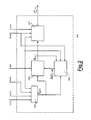
- FIG. 1 shows a functional block diagram of the echo canceller which is the object of the present invention,
- FIG. 2 shows in greater detail the block designated by CAC in FIG. 1, and
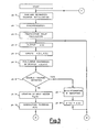
- FIGS. 3, 4 and 5 are flow charts of the program for the echo canceller shown in FIG. 1.
- With reference to FIG. 1 there may be seen an echo canceller CANC which is the object of the present invention located near an international telephone exchange RTI and placed in series with a 4-wire telephone line which connects said exchange to a national exchange RTN.
- The 4-wire line L4 is connected through the exchange RTN to a hybrid coil HIB which in turn is connected to a telephone set TEL by a 2-wire line L2.
- The echo canceller CANC has four terminals designated Rin, Rout, Sin and Sout having the following meanings.
- The terminal Rin is the input of a signal x(t) which represents the voice of the far-end talker.
- The terminal Rout is the output of said signal x(t).
- The terminal Sin is the input of a signal d(t) which can be either the voice of the near-end talker or the echo of the signal x(t) or both superimposed.
- The terminal Sout is the output of a signal e (t) which represents either the voice of the near-end talker or, as will be better explained below, a residual echo of the signal x(t).
- In the case under examination all the signals indicated in the figures are digital, therefore the temporal variable (t) is a discrete variable which undergoes increments of 125/1.s each equal to the period P of the sampling frequency of the signals x(t) and d(t).
- The terminals Rin and Sout of the canceller CANC are connected to the international telephone exchange RTI.
- On the connection between the terminal Rout of CANC and the reception side of the line L4 (with reference to the exchange RTN) there is inserted an attenuator ATT. The terminal Rout is also connected to an input of a double talking detector block RDC.
- The terminal Sin is connected to the other input of the block RDC and to the transmission side of the line L4 (with reference to the exchange RTN).
- When the block RDC detects on the line L4 the simultaneous presence of voice signals from both talkers, it generates a signal INT which disables the canceller CANC and inserts the attenuator ATT.
- The echo canceller CANC is functionally divisible in the blocks (a) a recursive digital filter FTR with adaptive coefficients which produces a signal d(t) which is an estimate of the echo d(t), (b) a block CAC which calculates the adaptive coefficients of the filter FTR by means of an appropriate adaptation algorithm, (c) a subtractive block SOT which subtracts the estimated echo from the actual echo, (d) a block RIT which calculates the echo propagation delay d(t) where by propagation delay is meant the total delay existing between the signal x(t) at the output Rout of the canceller and the signal d(t) at its input Sin, and (e) a block CNL designated 'center clipper' which can be considered a special case of echo suppressor accomplished in accordance with known techniques.
- The voice signal x(t) coming from the exchange RTI reaches the terminal Rin and thence reaches a first input of the blocks RIT, CAC, FTR and CNL.
- The echo signal d(t) coming from the exchange RTN reaches the terminal Sin and thence reaches a first input of the block SOT indicated in the figures by the symbol (+) and a second input of the blocks RIT, FTR and CAC.
- At the output of the block FTR there is the estimated echo signal d(t) which reaches the second input of the block SOT indicated in the figures by the symbol (-).
- At the output of the block SOT there is an error signal e(t) which reaches a second input of the block CNL and a third input of the block CAC.
- To a third input of the block FTR coming from the output of the block CAC there reaches a plurality of signals indicated in the figures by the vectorial symbol C N(t). Said plurality comprises the adaptive coefficients of the filter FTR, N being their number.
- The signal INT coming from the output of the block RDC arrives at the third input of the block CNL and the fourth input of the block CAC.
- The signal e (t) coming from the output of the block CNL reaches the third input of the block RIT and the terminal Sout of CANC. At the two outputs of the block RIT are present two signals designated INDX and INIB. The signal INIB is directed to a fifth input of the block CAC. The signal INDX which represents the propagation delay expressed as the number of intervals of duration 125u.s each is directed toward a sixth input of the block CAC and to a fourth input of the block FTR.
- In operation let us suppose for the sake of simplicity the voice of a single far-end talker and also that the echo canceller has already reached operating conditions, then examining the other cases. In the case mentioned the signal INT is not present and the attenuator ATT lets pass the signal x(t) unchanged to the exchange RTN whence it continues to the hybrid coil HIB and the telephone TEL.
- As mentioned above the hybrid coil HIB reflects a fraction of the signal x(t) on the line L4 again to the exchange RTN. Said signal fraction reaches the terminal Sin of the echo canceller CANC and is indicated in the figures as an echo signal d(t).
- The filter FTR performs the estimate d(t) of the echo d(t) and sends it to the subtractor SOT which in turn subtracts it from the actual echo d(t) to obtain the error signal e(t) = d(t) - d(t), also termed 'residual echo'.
- The block CNL is a residual echo silencing device which compares the residual echo samples e(t) with a threshhold value dependent upon the level of the signal x(t) . If the comparison shows that e(t) exceeds said fraction of x(t) the signal e(t) passes unchanged from the block CNL reaching the terminal Sout of the canceller; otherwise it is completely suppressed.
- The filter FTR uses in the canceller which is the object of the present invention a recurrent filter with adaptive coefficients whose transfer function have poles and zeros. Said filter also comprises a known delaying circuit which delays the voice samples x(t) for time t = t - INDX.
- Said filter is accomplished in accordance with the known art for the design of digital filters and has two filtering sections designated respectively forward predictor and backward predictor both of which have adaptive coefficients calculated by the block CAC. The adaptation algorithm will be explained entirely in the detailed description of the operation of the block CAC given with reference to FIG. 2.
- The estimate signal d(t) is obtained by a convolution process between the impulse response of the filter FTR and the inputs x(t) and d(t) in the manner indicated in the following formula.

- In the canceller described as an example there was adopted a filter FTR of the tenth order, consequently the numbers N1 and N2 are both equal to 10.
- The estimate of the echo signal d(t) can be expressed in a more compact manner using the following vecatorial symbols:-

where C N T(t) is the transposed vector of the adaptive coefficients ak and bk, N = N + N2, T is the generic transposition operator andX N(t) is the vector which represents the entirety of the samples x(t'-k) and d(t-k) which is known as a vector of the input signal of the adaptive canceller. Said vector is calculated by the delaying circuit included in the filter FTR. - The vectors
C N(t) andX N(t) are expressed as follows.
- The above discussion shows clearly that if the filter FTR obtains a good estimate of the echo d(t) even in the presence of phase roll said echo will be effectively blanked at the output Sout of the canceller thus avoiding production of its bothersome effects on the far-end talker.
- Now we shall discuss the other cases of operation of the echo canceller.
- In the case where the canceller is in the initial transitory phase in the presence of the voice of the far-end talker only the block RIT calculates the propagation delay of the actual echo signal d(t).
- The calculation is done by a process of correlation of the voice samples x(t) of the far-end talker with the actual echo samples d(t). Said correlation process determines the point of maximum resemblance of these two signals and thus identifies the propagation delay.
- During the calculation there is sent to the block CAC the signal INIB which causes zeroing of the vector of the adaptive coefficients
C N(t); otherwise in this phase the calculation algorithm would have a longer convergence time. - When the calculation is finished the block RIT removes the signal INIB and sends to the block CAC the signal INDX.
- In addition during rated operation of the canceller the block RIT holds the residual echo e (t) output from the center clipper CNL under constant observation. If it exceeds a certain predetermined threshhold it recalculates the propagation delay.
- Now we shall examine the case in which there is present the voice of the far-end talker and/or the near-end talker's.
- This condition is detected by the block RDC which keeps under constant observation the signals x(t) and d(t) comparing them appropriately with each other.
- Supposing that the hybrid coil HIBattenuates the echo signal by at least 6dB, if the difference of level between the signals x(t) and d(t) is less than 6db it means that on the line L4 there is either the simultaneous presence of the voices of the remote and near-end talkers or the presence of voice of the near-end talker only. Under these conditions, since the signal e(t) used by the block CAC would be basically voice of the near-end talker, the signal INT becomes active and zeros the coefficients ak and bk, interrupting the silencing of the residual echo to avoid cutting off said voice.
- With reference to FIG. 2 where the same signals of FIG. 1 are indicated by the same symbols we see the block CAC which calculates the adaptive coefficients of the filter FTR of FIG. 1. It consists of a block VET which calculates a vector
X N(t) identical with the input vector calculated by the filter FTR, a block MAI which calculates a matrix indicated byR NN1 (r-M) hereinafter defined as the inverse autocorrelation matrix of the vectorX N(t) (the meaning of the temporal variable r will be explained below), a block VGK which calculates a vectorK N(t) called hereinafter Kalman's gain vector, and lastly ACF which calculates the vector of the coefficientsC N(t) - The signals x(t) , d(t) and INDX reach the same number of inputs of the block VET which delays the samples of x(t) in relation to those of d(t) by a number of sampling periods expressed by INDX to output the vector
X N(t) Said vector is placed at a first input of the blocks VGK and MAI. - In view of the above it can be understood how the functions of the delaying circuit included in the filter FTR can actually be performed by the block VET.
- The output of the block VGK is the vector
K N(t) which reaches a first input of the block ACF and a second input of the block MAI. The output of the block MAI is the matrixR NN 1 (T-M) placed at a second input of the block VGK. - The signal (e)t reaches a first input of the block ACF whose output is the vector of the coefficients C N-(t). The signal INIB reaches both a second input of the block ACF, causing zeroing of said vector of the coefficients, and a third input of the block MAI causing initializing of the matrix
R N N 1 (r-M). - The signal INT reaches an input of all the blocks belonging to the block CAC and disables their operation.
- The adaptation algorithm of the coefficients was developed in an innovative manner starting from a known algorithm such as conventional Kalman. A detailed description of Kalman is given for example on pages 413-417 of the book entitled 'Digital Communication' by John G. Proakis published by International Student Editions.
- The optmization criterion of the coefficients on which is based the Kalman algorithm is minimization of the mean square error or of the power of the residual echo e(t).
- Kalman's algorithm has a reduced convergence time approximately equal to N x P where N is the number of the adaptive coefficients and P is the sampling frequency period of the signals x(t) and d(t).
- On the other hand adaptation of the coefficients involves considerable complexity of calculation and consequently long processing time.
- To overcome this drawback the innovative criterion defined above 'decimation of the square error' was introduced in the calculation of the adaptive coefficients.
- In view of the above the blocks VGK, MAI and ACF update their outputs at each iteration. But the block VET updates the vector
X N(t) at each sampling period P because decimation of the square error and not of the voice signal of the talker is made. - Decimation brings the benefit of reducing by a factor Ma considerable part of the arithmetical operations performed by Kalman's algorithm in each sampling interval, allowing great simplification of the circuits which perform it. It simultaneously reduces by approximately one factor M the convergence speed of Kalman's algorithm but this drawback is overcome by the fact that the convergence speed is very high.
- M = 3 was chosen as a value allowing compensation of a 4Hz phase roll and implementation of several echo cancellers with a single microprocessor specialized in digital-signal processing.
- The decimated mean square error represented by e(t) is expressed in the following manner:-

- ∈(6) - λ6e2(0) + λ3e2(3) + λoe2(6)
- Minimization of the decimated mean square error e(t) is obtained by making equal to zero its partial derivative made in relation to the adaptive coefficients N. This operation leads to a linear system which, omitting all the mathematical passages known per se, is expressed by the following equation known as the Wiener-Hopf equation:-

where CN(t) indicates the vector of the adaptive coefficients ak and bk,R NN(t) indicates the following autocorrelating matrix of the input vectorX Nt) :- -

-

- The solution of equation (5) is as follows:-

R N N(t) is the inverse autocorrelation vector of the input X N(t) which enjoys the symmetry property with repect to the principal diagonal. - The algorithm seeks iteratively the solution to the equation (5), thus avoiding solving the system of N equations expressed by (8) at each new block of M samples of
X N(t) received by the block CAC. - It assumes knowledge of the solution of the equation (8) at instant T-M and therefrom is derived the following solution at instant t calculated by the block ACF:-

- The term
K N(τ) is an N-dimensional vector called Kalman's gain vector and defined as:-
R N N1 (r-M) is the inverse autocorrelation matrix of the input vector T N(1-M) calculated recursively using the following expression:-
- For the congruity of the entire iterative process expressed in (9), (10) and (11) there is initialized in a nonlimiting manner both the vector of the adaptive coefficients zeroing its elements and the autocorrelation matrix zeroing all its elements excepting those belonging to the principal diagonal placed at a very small value to ensure nonsingularity of the matrix.
- As can be seen in (9) the present value of the coefficients is obtained by adding to the value they have at a certain prior instant the present value (t), a correction step given by
K N(τ) and e(r). - FIGS. 3, 4 and 5 are flow charts of the sequence of operations performed by a microprocessor specialized in digital signal processing and used to implement the echo canceller which is the object of the present invention.
- In phase 0 (FIG. 3) are performed the operations of initialization of the reading and writing memory and of some registers of the microprocessor such as for example the square error decimation counter. In
phase 1 the unit then proceeds to the synchronization operation. - In
phase 2 is implemented the block RIT of FIG. 1 as regards calculation of the propagation delay of the actual echo d(t). In this phase which has a duration depending on the abovesaid delay the vector of the adaptive coefficients is zeroed. - In phases 3 and 4 are performed the operations of output of the samples e (t) and input of the samples x(t) and d(t) respectively. In
phase 5 is performed conversion of the signals x(t) and d(t) codified inPCM 8 bits compressed in accordance with law A in signals codified in linear form at 13 bits. This operation is performed by means of a conversion table contained in a read-only memory inside the microprocessor. Conversion takes place using the PCM signal to address the corresponding linear signal contained in the memory. - With
phase 6 processing the unit implements the double talking detector RDC of FIG. 1. In particular inphase 6 the unit compares the two signals x(t) and d(t) and, as explained in detail in the description of the block RDC, detects the double talking condition. If the condition is verified, inphase 7 the unit inserts a 6dB attenuation on the receiving side, block ATT of FIG. 1 and inphase 8 inhibits silencing of the residual echo e (t) and zeroes the vector of the adaptive coefficients, returning then to thedata output phase 3. If the double talking condition is not verified it means that there is voice only of the far-end talker and in this case the unit continues to process the subsequent phases. - In
phase 9 the unit updates the vector VN(t) of the input samples, formula (3), eliminating the samples x(t' -N1) and d(t-N2), moving the remaining samples one position and inserting the sample x(t -1) at the head of the N1 voice samples of the far-end talker and the sample d(t-1) at the head of the N2 actual echo samples to be processed. - In
phase 10 the microprocessor implements the recursive convolution filter FTR of FIG. 1 to obtain the estimated echo d(t) in accordance with formula (2). - In phase 11 (FIG. 4) the unit calculates the residual echo, or error signal e(t), from the difference between the actual echo d(t) and the estimated echo d(t), block SOT of FIG. 1.
- By processing
phases phase 12 the unit compares the signal e(t) with an appropriate threshhold depending on the signal x(t). If e-(t) is less than said threshhold, inphase 13 there is created silencing of the residual echo. Otherwise the programme goes directly fromphase 12 tophase 14, bypassingphase 13, to allow the signal e(t) to pass unchanged to the output of the canceller. - In
phase 14 is performed another function of the block RIT of FIG. 1, i.e. monitoring of the signal e (t) which comes out of the canceller. If an appropriate fraction of the signal x(t) is less than the value of the samples of e'(t) there is a leap tophase 0 which reinitializes the unit and recalculates the propagation delay because very probably it is considerably changed. If the previous condition is not verified the programme goes intophase 15. - It is useful to remember that, because of processing complexity, calculation of Kalman's N-dimensional gain vector, updating of the inverse autocorrelation matrix of the order N x N and updating of the N-dimensional vector of the adaptive coefficients, is completely performed only at each iteration including the M = 3 consecutive sampling intervals of duration 125u.s each designated frames 0, 1 and 2 respectively.
- The above calculations performed by the programme in
phases 17 to 24 inclusive are equally divided between the three frames. At the end of the processing for a generic frame the program returns cyclically to phase 3 (FIG. 3). -
Phases 15 and 16 (FIG. 4) are tests of the content of the decimation counter designed to establish in which of the frames the program has arrived. - In
frame 0 of the ith iteration the microprocessor increments the decimation counter, phase 17 (FIG. 5), so that the following work frame will beframe 1 of the same iteration and proceeds inphase 18 of the current frame with the partial calculation of Kalman's gain vector, performing 70% of the arithmetical operations necessary. - In
frame 1 of the ith iteration the microprocessor increments the decimation counter,phase 19, so that the following work frame will beframe 2 of the same iteration and proceeds inphase 20 of the current frame to completion of the calculation of Kalman's gain vector. In thefollowing phase 21 of said frame the unit partially updates the inverse autocorrelation matrix, performing 40% of the arithmetical operations. - In the last frame of the ith iteration the microprocessor unit initializes the decimation counter,
phase 22, so that the following work frame will be frame 0 (i + 1)th iteration. Then inphase 23 of the current frame it completes updating of the inverse autocorrelation matrix. In thefollowing phase 24 of said frame the unit calculates the new value of the elements belonging to the vector of the adaptive filter coefficients by applying formula (9). Then it substitutes the old values with the present values. - From the description given the advantages of the procedure and device for adaptive digital cancellation of the echo generated in telephone connections with time-variant characteristics which is the object of the present invention are clear.
- In particular they are the fact that the echo canceller obtained by said procedure estimates the echo signal by means of a recursive digital filter with adaptive coefficients which, compared with the transversal filter of conventional echo cancellers, has the double advantage of allowing a more accurate estimate and having a smaller number of coefficients to update.
- The adaptation algorithm implemented has a convergence speed higher than that of the gradient algorithm used in the conventional echo cancellers, allowing the echo canceller which is the object of the present invention to maintain good performance even in the presence of a 4Hz phase roll.
- In addition the 'decimation of the square error' in the calculation of the adaptive coefficients allows simplification of the circuitry and makes it possible .to obtain several echo cancellers with a single microprocessor specialized in digital signal processing.
Claims (15)


Priority Applications (1)
| Application Number | Priority Date | Filing Date | Title |
|---|---|---|---|
| AT89203107T ATE87779T1 (en) | 1988-12-21 | 1989-12-07 | METHOD AND ARRANGEMENT FOR ADAPTIVE DIGITAL CANCELING OF THE ECHO CREATED IN TELEPHONE CONNECTIONS WITH TIME-VARIANT CHARACTERISTICS. |
Applications Claiming Priority (2)
| Application Number | Priority Date | Filing Date | Title |
|---|---|---|---|
| IT8823032A IT1228106B (en) | 1988-12-21 | 1988-12-21 | PROCEDURE AND DEVICE FOR THE ADAPTIVE NUMERIC CANCELLATION OF THE ECO GENERATED IN TELEPHONE CONNECTIONS WITH CHARACTERISTICS VARIED OVER TIME |
| IT2303288 | 1988-12-21 |
Publications (3)
| Publication Number | Publication Date |
|---|---|
| EP0375015A2 true EP0375015A2 (en) | 1990-06-27 |
| EP0375015A3 EP0375015A3 (en) | 1992-04-01 |
| EP0375015B1 EP0375015B1 (en) | 1993-03-31 |
Family
ID=11203092
Family Applications (1)
| Application Number | Title | Priority Date | Filing Date |
|---|---|---|---|
| EP89203107A Expired - Lifetime EP0375015B1 (en) | 1988-12-21 | 1989-12-07 | Method and device for adaptive digital cancellation of the echo generated in telephone connections with time-variant characteristics |
Country Status (5)
| Country | Link |
|---|---|
| EP (1) | EP0375015B1 (en) |
| AT (1) | ATE87779T1 (en) |
| DE (1) | DE68905782T2 (en) |
| ES (1) | ES2041980T3 (en) |
| IT (1) | IT1228106B (en) |
Cited By (6)
| Publication number | Priority date | Publication date | Assignee | Title |
|---|---|---|---|---|
| ES2038887A2 (en) * | 1991-04-18 | 1993-08-01 | Aplicaciones Electronicas Quas | Digital hybrid for multiconferencing |
| ES2038904A2 (en) * | 1991-09-10 | 1993-08-01 | Alcatel Standard Electrica | Method and device for acoustic echo adaptive cancellation. |
| EP0557829A2 (en) * | 1992-02-24 | 1993-09-01 | Siemens Telecomunicazioni S.P.A. | Process and device for adaptive digital cancellation of the echo generated in non-stationary telephone connections |
| WO1996025805A1 (en) * | 1995-02-15 | 1996-08-22 | Telefonaktiebolaget Lm Ericsson (Publ) | Echo canceller having kalman filter for optimal adaptation |
| US5737410A (en) * | 1993-12-23 | 1998-04-07 | Nokia Telecommunication Oy | Method for determining the location of echo in an echo canceller |
| DE19580846C1 (en) * | 1994-07-14 | 2000-11-16 | Motorola Inc | Method for echo cancellation with double speech immunity |
Citations (2)
| Publication number | Priority date | Publication date | Assignee | Title |
|---|---|---|---|---|
| JPS57212831A (en) * | 1981-06-24 | 1982-12-27 | Kokusai Denshin Denwa Co Ltd <Kdd> | Echo controlling system |
| EP0137508A1 (en) * | 1983-10-12 | 1985-04-17 | CSELT Centro Studi e Laboratori Telecomunicazioni S.p.A. | Method of and device for the digital cancellation of the echo generated in connections with time-varying characteristics |
-
1988
- 1988-12-21 IT IT8823032A patent/IT1228106B/en active
-
1989
- 1989-12-07 ES ES198989203107T patent/ES2041980T3/en not_active Expired - Lifetime
- 1989-12-07 DE DE8989203107T patent/DE68905782T2/en not_active Expired - Fee Related
- 1989-12-07 EP EP89203107A patent/EP0375015B1/en not_active Expired - Lifetime
- 1989-12-07 AT AT89203107T patent/ATE87779T1/en not_active IP Right Cessation
Patent Citations (2)
| Publication number | Priority date | Publication date | Assignee | Title |
|---|---|---|---|---|
| JPS57212831A (en) * | 1981-06-24 | 1982-12-27 | Kokusai Denshin Denwa Co Ltd <Kdd> | Echo controlling system |
| EP0137508A1 (en) * | 1983-10-12 | 1985-04-17 | CSELT Centro Studi e Laboratori Telecomunicazioni S.p.A. | Method of and device for the digital cancellation of the echo generated in connections with time-varying characteristics |
Non-Patent Citations (3)
| Title |
|---|
| IEEE INTERNATIONAL CONFERENCE ON COMMUNICATIONS, PROCEEDINGS, Chicago, Illinois, 23rd - 26th June 1985, vol. 3, pages 1477-1481, New York, US; S.T. ALXANDER et al.: "Adaptive telephony echo cancellation using fast kalman pole-zero modeling" * |
| J.G. PROAKIS: "Digital Communications", International Student Edition, 1983, pages 413-417, McGraw-Hill International Book Co., Singapore * |
| PATENT ABSTRACTS OF JAPAN, vol. 7, no. 65 (E-165)[1210], 18th March 1983; & JP-A-57 212 831 (KOKUSAI DENSHIN) 27-12-1982 * |
Cited By (12)
| Publication number | Priority date | Publication date | Assignee | Title |
|---|---|---|---|---|
| ES2038887A2 (en) * | 1991-04-18 | 1993-08-01 | Aplicaciones Electronicas Quas | Digital hybrid for multiconferencing |
| ES2038904A2 (en) * | 1991-09-10 | 1993-08-01 | Alcatel Standard Electrica | Method and device for acoustic echo adaptive cancellation. |
| EP0557829A2 (en) * | 1992-02-24 | 1993-09-01 | Siemens Telecomunicazioni S.P.A. | Process and device for adaptive digital cancellation of the echo generated in non-stationary telephone connections |
| US5414766A (en) * | 1992-02-24 | 1995-05-09 | Siemens Telecommunicazioni S.P.A. | Process and device for adaptive digital cancellation of the echo generated in time-varying telephone connections |
| EP0557829A3 (en) * | 1992-02-24 | 1995-08-02 | Sits Soc It Telecom Siemens | Process and device for adaptive digital cancellation of the echo generated in non-stationary telephone connections |
| US5737410A (en) * | 1993-12-23 | 1998-04-07 | Nokia Telecommunication Oy | Method for determining the location of echo in an echo canceller |
| DE19580846C1 (en) * | 1994-07-14 | 2000-11-16 | Motorola Inc | Method for echo cancellation with double speech immunity |
| WO1996025805A1 (en) * | 1995-02-15 | 1996-08-22 | Telefonaktiebolaget Lm Ericsson (Publ) | Echo canceller having kalman filter for optimal adaptation |
| AU698609B2 (en) * | 1995-02-15 | 1998-11-05 | Telefonaktiebolaget Lm Ericsson (Publ) | Echo canceller having Kalman filter for optimal adaptation |
| US5995620A (en) * | 1995-02-15 | 1999-11-30 | Telefonaktiebolaget Lm Ericsson | Echo canceller having Kalman filter for optimal adaptation |
| CN1084978C (en) * | 1995-02-15 | 2002-05-15 | 艾利森电话股份有限公司 | Echo canceller having kalman filter for optimal adaptation |
| KR100375277B1 (en) * | 1995-02-15 | 2004-02-11 | 텔레폰아크티에볼라게트 엘엠 에릭슨 | Echo cancellation device with Kalman filter for optimum adaptation |
Also Published As
| Publication number | Publication date |
|---|---|
| ES2041980T3 (en) | 1993-12-01 |
| IT8823032A0 (en) | 1988-12-21 |
| EP0375015A3 (en) | 1992-04-01 |
| ATE87779T1 (en) | 1993-04-15 |
| EP0375015B1 (en) | 1993-03-31 |
| IT1228106B (en) | 1991-05-28 |
| DE68905782T2 (en) | 1993-08-26 |
| DE68905782D1 (en) | 1993-05-06 |
Similar Documents
| Publication | Publication Date | Title |
|---|---|---|
| US5418849A (en) | Procedure and device for adaptive digital cancellation of the echo generated in telephone connections with time-variant characteristics | |
| US4535206A (en) | Echo cancellation in two-wire full-duplex data transmission with estimation of far-end data components | |
| EP0557829B1 (en) | Process and device for adaptive digital cancellation of the echo generated in non-stationary telephone connections | |
| US4562312A (en) | Subsampling delay estimator for an echo canceler | |
| US5737410A (en) | Method for determining the location of echo in an echo canceller | |
| US5388092A (en) | Echo canceller for two-wire full duplex digital data transmission | |
| CA1063744A (en) | Echo canceller for two-wire pull duplex data transmission | |
| US5117418A (en) | Frequency domain adaptive echo canceller for full-duplex data transmission | |
| US5590121A (en) | Method and apparatus for adaptive filtering | |
| EP1829351B1 (en) | Isolation of transmit and receive signals | |
| JP2503747B2 (en) | FIR type eco-canceller | |
| EP0384490A2 (en) | Echo canceller having FIR and IIR filters for cancelling long tail echoes | |
| US4587382A (en) | Echo canceller using end delay measurement | |
| EP0727882B1 (en) | Echo cancellation and suppression | |
| EP0106640B1 (en) | Noise control circuit | |
| CA1175521A (en) | Echo cancellation in two-wire full-duplex data transmission with estimation of far-end data components | |
| US7068780B1 (en) | Hybrid echo canceller | |
| EP0375015B1 (en) | Method and device for adaptive digital cancellation of the echo generated in telephone connections with time-variant characteristics | |
| US5649011A (en) | Method for the adaptive control of a digital echo canceller in a telecommunication system | |
| EP0014044A1 (en) | Method and system for reducing conference bridge oscillations | |
| KR100561390B1 (en) | Digital echo cancellation device | |
| US6856684B1 (en) | Device and method for echo compensation in a two-wire full duplex channel transmission method | |
| US20050243994A1 (en) | Echo canceller having a frequency domain active region location estimator | |
| JP2594687B2 (en) | Echo canceller | |
| AU719761B2 (en) | Echo cancellation method and circuit |
Legal Events
| Date | Code | Title | Description |
|---|---|---|---|
| PUAI | Public reference made under article 153(3) epc to a published international application that has entered the european phase |
Free format text: ORIGINAL CODE: 0009012 |
|
| AK | Designated contracting states |
Kind code of ref document: A2 Designated state(s): AT BE CH DE ES FR GB GR IT LI NL SE |
|
| PUAL | Search report despatched |
Free format text: ORIGINAL CODE: 0009013 |
|
| AK | Designated contracting states |
Kind code of ref document: A3 Designated state(s): AT BE CH DE ES FR GB GR IT LI NL SE |
|
| 17P | Request for examination filed |
Effective date: 19920424 |
|
| 17Q | First examination report despatched |
Effective date: 19920817 |
|
| GRAA | (expected) grant |
Free format text: ORIGINAL CODE: 0009210 |
|
| AK | Designated contracting states |
Kind code of ref document: B1 Designated state(s): AT BE CH DE ES FR GB GR IT LI NL SE |
|
| REF | Corresponds to: |
Ref document number: 87779 Country of ref document: AT Date of ref document: 19930415 Kind code of ref document: T |
|
| REF | Corresponds to: |
Ref document number: 68905782 Country of ref document: DE Date of ref document: 19930506 |
|
| ET | Fr: translation filed | ||
| ITF | It: translation for a ep patent filed |
Owner name: SIEMENS - ING. CORRADO BORSANO |
|
| REG | Reference to a national code |
Ref country code: GR Ref legal event code: FG4A Free format text: 3008227 |
|
| REG | Reference to a national code |
Ref country code: ES Ref legal event code: FG2A Ref document number: 2041980 Country of ref document: ES Kind code of ref document: T3 |
|
| PLBE | No opposition filed within time limit |
Free format text: ORIGINAL CODE: 0009261 |
|
| STAA | Information on the status of an ep patent application or granted ep patent |
Free format text: STATUS: NO OPPOSITION FILED WITHIN TIME LIMIT |
|
| 26N | No opposition filed | ||
| EAL | Se: european patent in force in sweden |
Ref document number: 89203107.1 |
|
| PGFP | Annual fee paid to national office [announced via postgrant information from national office to epo] |
Ref country code: CH Payment date: 19970319 Year of fee payment: 8 |
|
| PGFP | Annual fee paid to national office [announced via postgrant information from national office to epo] |
Ref country code: GB Payment date: 19971113 Year of fee payment: 9 |
|
| PGFP | Annual fee paid to national office [announced via postgrant information from national office to epo] |
Ref country code: AT Payment date: 19971126 Year of fee payment: 9 |
|
| PGFP | Annual fee paid to national office [announced via postgrant information from national office to epo] |
Ref country code: ES Payment date: 19971205 Year of fee payment: 9 |
|
| PGFP | Annual fee paid to national office [announced via postgrant information from national office to epo] |
Ref country code: BE Payment date: 19971212 Year of fee payment: 9 |
|
| PGFP | Annual fee paid to national office [announced via postgrant information from national office to epo] |
Ref country code: GR Payment date: 19971219 Year of fee payment: 9 Ref country code: FR Payment date: 19971219 Year of fee payment: 9 |
|
| PGFP | Annual fee paid to national office [announced via postgrant information from national office to epo] |
Ref country code: SE Payment date: 19971222 Year of fee payment: 9 Ref country code: NL Payment date: 19971222 Year of fee payment: 9 |
|
| PG25 | Lapsed in a contracting state [announced via postgrant information from national office to epo] |
Ref country code: LI Free format text: LAPSE BECAUSE OF NON-PAYMENT OF DUE FEES Effective date: 19971231 Ref country code: CH Free format text: LAPSE BECAUSE OF NON-PAYMENT OF DUE FEES Effective date: 19971231 |
|
| PGFP | Annual fee paid to national office [announced via postgrant information from national office to epo] |
Ref country code: DE Payment date: 19980220 Year of fee payment: 9 |
|
| REG | Reference to a national code |
Ref country code: CH Ref legal event code: PL |
|
| PG25 | Lapsed in a contracting state [announced via postgrant information from national office to epo] |
Ref country code: GB Free format text: LAPSE BECAUSE OF NON-PAYMENT OF DUE FEES Effective date: 19981207 Ref country code: AT Free format text: LAPSE BECAUSE OF NON-PAYMENT OF DUE FEES Effective date: 19981207 |
|
| PG25 | Lapsed in a contracting state [announced via postgrant information from national office to epo] |
Ref country code: SE Free format text: LAPSE BECAUSE OF NON-PAYMENT OF DUE FEES Effective date: 19981208 |
|
| PG25 | Lapsed in a contracting state [announced via postgrant information from national office to epo] |
Ref country code: ES Free format text: LAPSE BECAUSE OF THE APPLICANT RENOUNCES Effective date: 19981209 |
|
| PG25 | Lapsed in a contracting state [announced via postgrant information from national office to epo] |
Ref country code: GR Free format text: LAPSE BECAUSE OF NON-PAYMENT OF DUE FEES Effective date: 19981231 Ref country code: BE Free format text: LAPSE BECAUSE OF NON-PAYMENT OF DUE FEES Effective date: 19981231 |
|
| BERE | Be: lapsed |
Owner name: SIEMENS TELECOMUNICAZIONI S.P.A. Effective date: 19981231 |
|
| PG25 | Lapsed in a contracting state [announced via postgrant information from national office to epo] |
Ref country code: NL Free format text: LAPSE BECAUSE OF NON-PAYMENT OF DUE FEES Effective date: 19990701 |
|
| GBPC | Gb: european patent ceased through non-payment of renewal fee |
Effective date: 19981207 |
|
| PG25 | Lapsed in a contracting state [announced via postgrant information from national office to epo] |
Ref country code: FR Free format text: LAPSE BECAUSE OF NON-PAYMENT OF DUE FEES Effective date: 19990831 |
|
| NLV4 | Nl: lapsed or anulled due to non-payment of the annual fee |
Effective date: 19990701 |
|
| REG | Reference to a national code |
Ref country code: FR Ref legal event code: ST |
|
| PG25 | Lapsed in a contracting state [announced via postgrant information from national office to epo] |
Ref country code: DE Free format text: LAPSE BECAUSE OF NON-PAYMENT OF DUE FEES Effective date: 19991001 |
|
| REG | Reference to a national code |
Ref country code: ES Ref legal event code: FD2A Effective date: 20010402 |
|
| PG25 | Lapsed in a contracting state [announced via postgrant information from national office to epo] |
Ref country code: IT Free format text: LAPSE BECAUSE OF NON-PAYMENT OF DUE FEES;WARNING: LAPSES OF ITALIAN PATENTS WITH EFFECTIVE DATE BEFORE 2007 MAY HAVE OCCURRED AT ANY TIME BEFORE 2007. THE CORRECT EFFECTIVE DATE MAY BE DIFFERENT FROM THE ONE RECORDED. Effective date: 20051207 |