EP0372575B1 - Encoder installing structure - Google Patents
Encoder installing structure Download PDFInfo
- Publication number
- EP0372575B1 EP0372575B1 EP89122701A EP89122701A EP0372575B1 EP 0372575 B1 EP0372575 B1 EP 0372575B1 EP 89122701 A EP89122701 A EP 89122701A EP 89122701 A EP89122701 A EP 89122701A EP 0372575 B1 EP0372575 B1 EP 0372575B1
- Authority
- EP
- European Patent Office
- Prior art keywords
- sheave
- hinge
- roller
- support member
- encoder
- Prior art date
- Legal status (The legal status is an assumption and is not a legal conclusion. Google has not performed a legal analysis and makes no representation as to the accuracy of the status listed.)
- Expired - Lifetime
Links
- 230000005540 biological transmission Effects 0.000 description 4
- 238000010276 construction Methods 0.000 description 3
- 238000000034 method Methods 0.000 description 1
- 238000003466 welding Methods 0.000 description 1
Images

Classifications
-
- B—PERFORMING OPERATIONS; TRANSPORTING
- B66—HOISTING; LIFTING; HAULING
- B66B—ELEVATORS; ESCALATORS OR MOVING WALKWAYS
- B66B1/00—Control systems of elevators in general
- B66B1/34—Details, e.g. call counting devices, data transmission from car to control system, devices giving information to the control system
- B66B1/3492—Position or motion detectors or driving means for the detector
-
- B—PERFORMING OPERATIONS; TRANSPORTING
- B66—HOISTING; LIFTING; HAULING
- B66B—ELEVATORS; ESCALATORS OR MOVING WALKWAYS
- B66B5/00—Applications of checking, fault-correcting, or safety devices in elevators
- B66B5/02—Applications of checking, fault-correcting, or safety devices in elevators responsive to abnormal operating conditions
- B66B5/04—Applications of checking, fault-correcting, or safety devices in elevators responsive to abnormal operating conditions for detecting excessive speed
-
- G—PHYSICS
- G01—MEASURING; TESTING
- G01P—MEASURING LINEAR OR ANGULAR SPEED, ACCELERATION, DECELERATION, OR SHOCK; INDICATING PRESENCE, ABSENCE, OR DIRECTION, OF MOVEMENT
- G01P1/00—Details of instruments
- G01P1/04—Special adaptations of driving means
Definitions
- the present invention relates to an installing structure of an encoder particularly to an installing structure of the encoder to a sheave.
- An object of the present invention is, therefore, to provide an installing structure of the encoder capable of determining a necessary data such as the velocity of the moving object based upon the rotational moving quantity of the sheave.
- an encoder installing structure is constructed such that a driving force is provided by a driving means to a rotor arranged on a circumference surface of a sheave to always apply a predetermined normal load to the sheave in a direction toward the axis line of the sheave at a contact portion with the sheave circumference surface.
- Subject-matter of the invention is an installing structure of encoder means having a roller contacting the circumferential surface of a sheave, the installing structure comprising:
- An installing structure of encoder means according to the preamble of claim 1 and an elevator system according to the preamble of claim 5 are known from CA-A-954 718.
- the biasing means act in such a way on the support member that a momentum for pivoting the support member relative to the sheave is exerted.
- the encoder means With the installing structure of the encoder means it is possible to determine the velocity of a moving object based upon the rotational speed of the sheave.
- the rotational speed of the sheave is exactly transmitted to the one roller or to the two rollers.
- the installing structure of the encoder means according to the invention is particularly suited for an elevator system having a linear motor drive.
- the linear motor drive acts on a counterweight or on the elevator car, and the sheave onto which the rope is guided acts as an idler sheave rotated by the rope.
- the rotor (rotors) of the encoder applies (apply) a predetermined normal load in a direction toward the axis of the sheave at the contact portion(s) with the circumferential surface of the sheave.
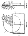
- Figs. 1 and 2 show a first preferred embodiment of the present invention.
- a rope 2 is wound up on a sheave 1 used for a traction-type elevator system.
- the sheave 1 is rotationally driven by a motor (not shown) to wind up the rope 2.
- the sheave 1 is an idler and is indirectly rotated by the movement of the rope 2.
- a roller 4 of a velocity detecting encoder 3 is arranged outside of the rope 2 so as to be in contact with the circumferential surface of the sheave 1.
- the roller 4 is coupled with a signal forming portion 6 so as to be freely rotatable by means of a rotating axis 5.
- the signal forming portion 6 is fixed to a movable bracket 7 by a bolt and a nut through an installing plate 8.
- the signal forming portion 6 is connected with a well-known system control apparatus (not shown) through a lead line L.
- the encoder end or upper end of a plate arm member 9 for rotating the movable bracket 7 is hinged at the lower portion of the signal forming portion 6.
- the movable bracket 7 is constructed so as to be freely movable around the hinged portion 10 relative to the arm member 9.
- the lower end of the arm member 9 is hinged to a fixing bracket 12 installed at a fixing portion 11 through a hinged portion 13, and the arm member 9 is constructed so as to be freely movable relative to the fixing bracket 12.
- an auxiliary bracket 14 is also fixed by bolts and nuts.
- an oval hole is made and a rod 17 is movably inserted through the oval hole.
- the upper end of the rod 17 is fixed to the lower end of a plate connecting member 18 by welding.
- the upper end of the connecting member 18 is fixed with the movable bracket 7 through bolt and nut.
- a compressed coil spring 19 is provided through spring sheets 20 and 21 between the lower portion of the other surface of approximately L-shaped bracket 15 and the lower end of the rod 17.
- the spring sheet 20 of the lower side is fixedly placed by a double nut 22 through washer.
- the apparatus is so constructed to place the axis lines A1 and A2 of the motor and of the hinged portion 10, the central lines C1 and C2 of the connecting member 18 and of the rod 17 in the same plane.
- a U-shaped member 23 provided at the fixing portion 11 fixes a shaft 24 to the fixing portion 11.
- the shaft 24 is equipped with the sheave 1 which is rotationally movable.
- the roller 4 of the encoder 3 For arranging the roller 4 of the encoder 3 at the circumferential surface of the sheave 1, first the arm member 9 and the movable bracket 7 are rotated while the spring 19 is free. At this time, the installed portion of the rod 17 becomes movable inside of the oval hole 16. Then, the spring 19 is compressed by the nuts 22 and 23 to give a predetermined biasing force when the axis line A3 of the sheave 1 or the shaft 24 is located on a plane including axis lines A1,A2 and central lines C1,C2.
- the roller 4 of the encoder 3 always applies a predetermined normal load to the sheave 1 at the contact portion with the circumferential surface of the sheave 1, realizing exact transmission of the rotational moving speed.
- the encoder as the encoder for detecting the velocity
- the present invention may apply to other encoders for detecting data in a similar manner.
- Figs. 3 and 4 represent a second preferred embodiment.
- the same members as those in the first embodiment are denoted by same symbols and the explanation thereof is omitted here.
- an encoder installing structure equipped with two encoders. At both ends of a movable bracket 30, encoders 33,34 are respectively installed through installing plates 31,32 in the same manner as in the first embodiment.
- the arm member 9 is installed at the movable bracket 30 between rollers 35 and 36 in a similar manner as in the first embodiment.
- the connecting member 18 is installed at the movable bracket 30 in the lower side of the hinged portion 10 between the movable bracket 30 and the arm member 9 in a similar manner as in the first embodiment.
- a first plane including the central lines C1 and C2 of the connecting member 18 and of the rod 17 and a second plane including the axis lines A1,A1 of the rollers 35,36 are orthogonally crossed.
- the axis line A2 of the hinged portion 10 is located in the first plane.
- the construction is such that the distance D1 between points on the lines A1 and A2 of the roller 35 and distance D2 between points on the lines A1 and A2 of the roller 36 are the same.
- the axis line A2 of the hinged portion 10 is also constructed to be located in the second plane; however, this is not always necessary and the object of the present invention may be realized by merely locating it in the first plane.
- the method of arranging the rollers 35 and 36 of the encoders 33 and 34 on the circumferential surface of the sheave 1 is almost the same as in the first embodiment, so that a predetermined biasing force is given by compressing the spring 19 through the nuts 22,22 when the axis line A3 is located in the first plane.
- the rollers 35 and 36 always apply predetermined uniform normal loads in a direction towards the axis line A3 of the sheave 1 at the respective contact portions with the circumferential surface of the sheave 1, resulting in exact transmission of the rotational moving speed of the sheave 1 to the respective rollers 35,36.
- the roller of the encoder applies a predetermined normal load to the sheave in the direction toward the axis line of thee sheave, realizing the exact transmission of the rotational moving speed to the roller.
- the plural rollers of the encoder always apply a predetermined uniform normal load of substantially the same value to the sheave in the direction toward the axis of the sheave, resulting in exact transmission of the rotational moving speed of the sheave to the respective rollers.
Landscapes
- Engineering & Computer Science (AREA)
- Automation & Control Theory (AREA)
- Physics & Mathematics (AREA)
- General Physics & Mathematics (AREA)
- Computer Networks & Wireless Communication (AREA)
- Types And Forms Of Lifts (AREA)
- Cage And Drive Apparatuses For Elevators (AREA)
- Indicating And Signalling Devices For Elevators (AREA)
- Maintenance And Inspection Apparatuses For Elevators (AREA)
- Elevator Control (AREA)
- Transmission And Conversion Of Sensor Element Output (AREA)
- Devices For Conveying Motion By Means Of Endless Flexible Members (AREA)
- Pulleys (AREA)
Description
characterized by:
- Fig. 1
- shows a front view of a first preferred embodiment of an encoder installing structure;
- Fig. 2
- a side view of the structure shown in Fig. 1;
- Fig. 3
- a front view of a second preferred embodiment of an encoder installing structure; and
- Fig. 4
- a side view of the structure shown in Fig. 3, with the lower roller removed.
Claims (10)
- An installing structure of encoder means (3;33,34) having a roller (4;35;36) contacting the circumferential surface of a sheave (1), the installing structure comprising:(a) a support member (7;30) supporting the roller (4;35;36) and being mounted in a pivotable manner;(b) biasing means (19) acting on the support member (7;30) so as to exert biasing force urging the roller (4;35;36) against the sheave surface;
characterized by:(c) an arm member (9) supporting the support member (7;30) by a first hinge (10) and mounted to a base member (12) by a second hinge (13);(d) the support member (7;30) supporting the encoder means (3;33,34) including the roller (4;35;36);(e) the acting point of the biasing force being located in a first plane which includes the axes (A3,A2) of the sheave (1) and of the first hinge (10);(f) a second plane which includes the axes (A2,A4) of the first hinge (10) and of the second hinge (13);(g) and the first and second planes intersecting each other. - The installing structure of claim 1, wherein the encoder means (33,34) comprise two rollers (35,36), contacting the circumferential surface of the sheave (1), and two signal forming portions (6).
- The installing structure of claim 2, wherein the distance (D1) between the axes of one of the rollers (35) and of the first hinge (10) is substantially the same as the distance (D2) between the axes of the other of the rollers (36) and of the first hinge (10).
- The installing structure of any one of claims 1 to 3, wherein the biasing means comprise a spring (19).
- An elevator system which comprises a sheave (1), encoder means (3;33,34) having a roller (4;35;36) contacting the circumferential surface of the sheave (1), and an installing structure of the encoder means (3; 33, 34), said structure comprising:(a) a support member (7;30) supporting the roller (4;35;36) and being mounted in a pivotable manner;(b) biasing means (19) acting on the support member (7;30) so as to exert biasing force urging the roller (4;35;36) against the sheave surface;
characterized by:(c) an arm member (9) supporting the support member (7;30) by a first hinge (10) and mounted to a base member (12) by a second hinge (13);(d) the support member (7;30) supporting the encoder means (3;33,34) including the roller (4;35;36);(e) the acting point of the biasing force being located in a first plane which includes the axes (A3,A2) of the sheave (1) and of the first hinge (10);(f) a second plane which includes the axes (A2,A4) of the first hinge (10) and of the second hinge (13);(g) and the first and second planes intersecting each other. - The elevator system of claim 5, wherein the encoder means (33,34) comprise two rollers (35,36), contacting the circumferential surface of the sheave (1), and two signal forming portions (6).
- The elevator system of claim 6, wherein the distance (D1) between the axes of one of the rollers (35) and of the first hinge (10) is substantially the same as the distance (D2) between the axes of the other of the rollers (36) and of the first hinge (10).
- The elevator system of any one of claims 5 to 7, wherein the biasing means comprise a spring (19).
- The elevator system of any one of claims 5 to 8,
wherein the elevator system comprises a linear motor drive. - The elevator system of any one of claims 5 to 9,
wherein the encoder means (3;33,34) determine the velocity of the elevator car.
Applications Claiming Priority (2)
| Application Number | Priority Date | Filing Date | Title |
|---|---|---|---|
| JP63311542A JP2505265B2 (en) | 1988-12-09 | 1988-12-09 | Encoder mounting structure |
| JP311542/88 | 1988-12-09 |
Publications (3)
| Publication Number | Publication Date |
|---|---|
| EP0372575A2 EP0372575A2 (en) | 1990-06-13 |
| EP0372575A3 EP0372575A3 (en) | 1992-05-13 |
| EP0372575B1 true EP0372575B1 (en) | 1998-03-25 |
Family
ID=18018492
Family Applications (1)
| Application Number | Title | Priority Date | Filing Date |
|---|---|---|---|
| EP89122701A Expired - Lifetime EP0372575B1 (en) | 1988-12-09 | 1989-12-08 | Encoder installing structure |
Country Status (6)
| Country | Link |
|---|---|
| US (1) | US5052522A (en) |
| EP (1) | EP0372575B1 (en) |
| JP (1) | JP2505265B2 (en) |
| DE (1) | DE68928616T2 (en) |
| ES (1) | ES2115586T3 (en) |
| FI (1) | FI100876B (en) |
Families Citing this family (5)
| Publication number | Priority date | Publication date | Assignee | Title |
|---|---|---|---|---|
| JP2875456B2 (en) * | 1992-09-17 | 1999-03-31 | 株式会社日立製作所 | Elevator equipment |
| TW284741B (en) * | 1992-09-17 | 1996-09-01 | Hitachi Ltd | |
| FI20095986A0 (en) | 2009-09-25 | 2009-09-25 | Kone Corp | Measuring system, electric drive and elevator system |
| CN110182679B (en) * | 2018-02-23 | 2022-04-26 | 奥的斯电梯公司 | Speed monitoring device and passenger transportation device |
| CN109775507B (en) * | 2019-03-14 | 2020-10-16 | 日立电梯(中国)有限公司 | Elevator, overspeed protection system and triggering device thereof |
Family Cites Families (6)
| Publication number | Priority date | Publication date | Assignee | Title |
|---|---|---|---|---|
| US613187A (en) * | 1898-10-25 | Speed-indicator for bicycles | ||
| US2105158A (en) * | 1935-01-08 | 1938-01-11 | Transp Devices Corp | Speedometer |
| CA954718A (en) * | 1972-04-25 | 1974-09-17 | Canadian General Electric Company Limited | Rope motion indicator for jammed conveyance detector for mine hoist |
| DE2742111A1 (en) * | 1977-09-19 | 1979-03-29 | Vdo Schindling | DISPLAY INSTRUMENT, IN PARTICULAR FOR VEHICLES |
| JPS581059U (en) * | 1981-06-26 | 1983-01-06 | 株式会社東芝 | Elevator position detection device |
| US4440024A (en) * | 1982-08-26 | 1984-04-03 | Westinghouse Electric Corp. | Tachogenerator |
-
1988
- 1988-12-09 JP JP63311542A patent/JP2505265B2/en not_active Expired - Lifetime
-
1989
- 1989-11-29 US US07/442,884 patent/US5052522A/en not_active Expired - Fee Related
- 1989-12-08 DE DE68928616T patent/DE68928616T2/en not_active Expired - Fee Related
- 1989-12-08 FI FI895867A patent/FI100876B/en not_active IP Right Cessation
- 1989-12-08 EP EP89122701A patent/EP0372575B1/en not_active Expired - Lifetime
- 1989-12-08 ES ES89122701T patent/ES2115586T3/en not_active Expired - Lifetime
Also Published As
| Publication number | Publication date |
|---|---|
| JP2505265B2 (en) | 1996-06-05 |
| ES2115586T3 (en) | 1998-07-01 |
| EP0372575A2 (en) | 1990-06-13 |
| FI100876B (en) | 1998-03-13 |
| DE68928616T2 (en) | 1998-11-05 |
| DE68928616D1 (en) | 1998-04-30 |
| US5052522A (en) | 1991-10-01 |
| FI895867A0 (en) | 1989-12-08 |
| EP0372575A3 (en) | 1992-05-13 |
| JPH02158576A (en) | 1990-06-19 |
Similar Documents
| Publication | Publication Date | Title |
|---|---|---|
| US5452605A (en) | Dynamometer for simulating the inertial and road load forces encountered by motor vehicles | |
| FI76541B (en) | LYFTMASKINERI. | |
| US3675482A (en) | Automatic tension sensing apparatus for belt conveyor | |
| ATE169714T1 (en) | COMPACT COUNTERWEIGHT SYSTEM FOR MULTIPLE DOORS | |
| CA1163591A (en) | Method of and apparatus for positioning the drive units of a plural drive escalator | |
| EP0372575B1 (en) | Encoder installing structure | |
| NO20015334L (en) | Device for measuring torque applied to the drum shaft of an elevator | |
| EP0718218A2 (en) | Conveyor belt | |
| CN1298484A (en) | Device for measuring the forces generated by rotor imbalance | |
| EP2141474B1 (en) | Apparatus for measuring forces which are produced by an unbalance of a rotary member | |
| US4832425A (en) | Rotation system for a rotating, tilting reflector | |
| US4347916A (en) | Roll guide shoe for elevators or the like | |
| US5717138A (en) | Arrangement for driving a measuring spindle of a balancing machine | |
| US4499768A (en) | Cantilever support for an apparatus to determine the imbalance in a rotating object | |
| US4440024A (en) | Tachogenerator | |
| CN1178320A (en) | Device for measuring torque | |
| JPS6160303B2 (en) | ||
| SU492778A1 (en) | Stand for examining wheels with elastic tires | |
| JPS6316694Y2 (en) | ||
| CN213932438U (en) | Meter counter | |
| JP3056550B2 (en) | Bicomponent force measuring device for rotating shaft with joint | |
| JP3652143B2 (en) | Robot swing mechanism | |
| JPH08282822A (en) | Overload stop mechanism for motor mounted on shaft | |
| SU894156A1 (en) | Reinforcement winding device | |
| SU948753A1 (en) | Bed for testing deck mechanisms |
Legal Events
| Date | Code | Title | Description |
|---|---|---|---|
| PUAI | Public reference made under article 153(3) epc to a published international application that has entered the european phase |
Free format text: ORIGINAL CODE: 0009012 |
|
| AK | Designated contracting states |
Kind code of ref document: A2 Designated state(s): CH DE ES FR GB IT LI |
|
| PUAL | Search report despatched |
Free format text: ORIGINAL CODE: 0009013 |
|
| AK | Designated contracting states |
Kind code of ref document: A3 Designated state(s): CH DE ES FR GB IT LI |
|
| 17P | Request for examination filed |
Effective date: 19921112 |
|
| 17Q | First examination report despatched |
Effective date: 19940321 |
|
| GRAG | Despatch of communication of intention to grant |
Free format text: ORIGINAL CODE: EPIDOS AGRA |
|
| GRAG | Despatch of communication of intention to grant |
Free format text: ORIGINAL CODE: EPIDOS AGRA |
|
| GRAH | Despatch of communication of intention to grant a patent |
Free format text: ORIGINAL CODE: EPIDOS IGRA |
|
| GRAH | Despatch of communication of intention to grant a patent |
Free format text: ORIGINAL CODE: EPIDOS IGRA |
|
| GRAA | (expected) grant |
Free format text: ORIGINAL CODE: 0009210 |
|
| ITF | It: translation for a ep patent filed | ||
| AK | Designated contracting states |
Kind code of ref document: B1 Designated state(s): CH DE ES FR GB IT LI |
|
| REG | Reference to a national code |
Ref country code: CH Ref legal event code: EP |
|
| ET | Fr: translation filed | ||
| REF | Corresponds to: |
Ref document number: 68928616 Country of ref document: DE Date of ref document: 19980430 |
|
| REG | Reference to a national code |
Ref country code: ES Ref legal event code: FG2A Ref document number: 2115586 Country of ref document: ES Kind code of ref document: T3 |
|
| REG | Reference to a national code |
Ref country code: CH Ref legal event code: NV Representative=s name: E. BLUM & CO. PATENTANWAELTE |
|
| PG25 | Lapsed in a contracting state [announced via postgrant information from national office to epo] |
Ref country code: GB Free format text: LAPSE BECAUSE OF NON-PAYMENT OF DUE FEES Effective date: 19981208 |
|
| PG25 | Lapsed in a contracting state [announced via postgrant information from national office to epo] |
Ref country code: LI Free format text: LAPSE BECAUSE OF NON-PAYMENT OF DUE FEES Effective date: 19981231 Ref country code: CH Free format text: LAPSE BECAUSE OF NON-PAYMENT OF DUE FEES Effective date: 19981231 |
|
| PLBE | No opposition filed within time limit |
Free format text: ORIGINAL CODE: 0009261 |
|
| STAA | Information on the status of an ep patent application or granted ep patent |
Free format text: STATUS: NO OPPOSITION FILED WITHIN TIME LIMIT |
|
| 26N | No opposition filed | ||
| GBPC | Gb: european patent ceased through non-payment of renewal fee |
Effective date: 19981208 |
|
| REG | Reference to a national code |
Ref country code: CH Ref legal event code: PL |
|
| PG25 | Lapsed in a contracting state [announced via postgrant information from national office to epo] |
Ref country code: FR Free format text: LAPSE BECAUSE OF NON-PAYMENT OF DUE FEES Effective date: 19990831 |
|
| REG | Reference to a national code |
Ref country code: FR Ref legal event code: ST |
|
| PG25 | Lapsed in a contracting state [announced via postgrant information from national office to epo] |
Ref country code: DE Free format text: LAPSE BECAUSE OF NON-PAYMENT OF DUE FEES Effective date: 19991001 |
|
| PG25 | Lapsed in a contracting state [announced via postgrant information from national office to epo] |
Ref country code: ES Free format text: LAPSE BECAUSE OF NON-PAYMENT OF DUE FEES Effective date: 19991209 |
|
| REG | Reference to a national code |
Ref country code: ES Ref legal event code: FD2A Effective date: 20000114 |
|
| PG25 | Lapsed in a contracting state [announced via postgrant information from national office to epo] |
Ref country code: IT Free format text: LAPSE BECAUSE OF NON-PAYMENT OF DUE FEES;WARNING: LAPSES OF ITALIAN PATENTS WITH EFFECTIVE DATE BEFORE 2007 MAY HAVE OCCURRED AT ANY TIME BEFORE 2007. THE CORRECT EFFECTIVE DATE MAY BE DIFFERENT FROM THE ONE RECORDED. Effective date: 20051208 |