EP0371724B1 - Method of automatically feeding wire to an electric discharge machine - Google Patents
Method of automatically feeding wire to an electric discharge machine Download PDFInfo
- Publication number
- EP0371724B1 EP0371724B1 EP89312283A EP89312283A EP0371724B1 EP 0371724 B1 EP0371724 B1 EP 0371724B1 EP 89312283 A EP89312283 A EP 89312283A EP 89312283 A EP89312283 A EP 89312283A EP 0371724 B1 EP0371724 B1 EP 0371724B1
- Authority
- EP
- European Patent Office
- Prior art keywords
- wire
- worked
- slit
- workpiece
- insert
- Prior art date
- Legal status (The legal status is an assumption and is not a legal conclusion. Google has not performed a legal analysis and makes no representation as to the accuracy of the status listed.)
- Expired - Lifetime
Links
- 238000000034 method Methods 0.000 title claims description 38
- 238000003754 machining Methods 0.000 claims description 84
- 238000000137 annealing Methods 0.000 claims description 63
- 230000004044 response Effects 0.000 claims description 18
- 230000003750 conditioning effect Effects 0.000 claims description 2
- 238000001514 detection method Methods 0.000 claims description 2
- 238000001816 cooling Methods 0.000 claims 3
- 238000010438 heat treatment Methods 0.000 claims 3
- 238000003780 insertion Methods 0.000 description 9
- 230000037431 insertion Effects 0.000 description 9
- 238000010586 diagram Methods 0.000 description 8
- 230000008569 process Effects 0.000 description 6
- XLYOFNOQVPJJNP-UHFFFAOYSA-N water Substances O XLYOFNOQVPJJNP-UHFFFAOYSA-N 0.000 description 5
- 230000002159 abnormal effect Effects 0.000 description 3
- 238000007796 conventional method Methods 0.000 description 3
- 239000012530 fluid Substances 0.000 description 3
- 230000007246 mechanism Effects 0.000 description 3
- 238000011144 upstream manufacturing Methods 0.000 description 3
- 230000009471 action Effects 0.000 description 2
- 230000000694 effects Effects 0.000 description 2
- 230000001771 impaired effect Effects 0.000 description 2
- 238000002347 injection Methods 0.000 description 2
- 239000007924 injection Substances 0.000 description 2
- 229910000760 Hardened steel Inorganic materials 0.000 description 1
- 229910045601 alloy Inorganic materials 0.000 description 1
- 239000000956 alloy Substances 0.000 description 1
- 230000000149 penetrating effect Effects 0.000 description 1
- 238000004804 winding Methods 0.000 description 1
Images



Classifications
-
- B—PERFORMING OPERATIONS; TRANSPORTING
- B23—MACHINE TOOLS; METAL-WORKING NOT OTHERWISE PROVIDED FOR
- B23H—WORKING OF METAL BY THE ACTION OF A HIGH CONCENTRATION OF ELECTRIC CURRENT ON A WORKPIECE USING AN ELECTRODE WHICH TAKES THE PLACE OF A TOOL; SUCH WORKING COMBINED WITH OTHER FORMS OF WORKING OF METAL
- B23H7/00—Processes or apparatus applicable to both electrical discharge machining and electrochemical machining
- B23H7/02—Wire-cutting
- B23H7/08—Wire electrodes
- B23H7/10—Supporting, winding or electrical connection of wire-electrode
Definitions
- the present invention relates to a method of automatically feeding a wire to an electric discharge machine which effects the discharge machining to a work by giving an electric discharge energy between the work and a wire electrode.
- the work such as a super hard alloy and a hardened steel are machined using a portion where the wire electrode runs, and the wire is usually fed by an automatic wire feeding device.
- Conventional automatic wire feeding devices can be divided into those of a pipe guide system, those of a water stream guide system, and those of a start hole guide system.
- Fig. 9 illustrates an automatic wire feeder based on the start hole guide system.
- the automatic wire feeder according to the start hole guide system is achieved by positioning the wire feeder at a start hole 26 formed in a work 8, penetrating a wire electrode through the start hole 26 via a wire feeder device 28, a feeder pipe and an upper guide 32, and pulling out the wire electrode 1 by the lead rollers located on the downstream side of a lower guide 29.
- the start hole system has a merit in that the wire can be penetrated even when the start hole 26 has a small diameter as well as a demerit in that the wire electrode itself must be composed of a hard wire.
- Fig. 10 illustrates an automatic wire feeder based on the pipe guide system.
- the automatic wire feeder according to the pipe guide system is achieved by positioning the wire feeder at a start hole 26 formed in the work 8, passing a pipe 27 that works as a guide through the start hole 26, actuating the wire feeder device 28 to pass the wire electrode 1 through the pipe 27, and pulling out the wire electrode 1 by the lead rollers positioned on the downstream side of the lower guide 29.
- the pipe guide system has a merit in that the feeding of wire electrode can be achieved maintaining a very high success rate as well as a demerit that the start hole 26 must have a large diameter since the pipe 27 that serves as a guide must be passed through the start hole 26.
- Fig. 11 illustrates an automatic wire feeder based on the water stream guide system.
- the automatic wire feeder based on the water stream guide system is achieved by positioning the wire feeder at a start hole 26 formed in the work 8, injecting a working fluid 31 into the start hole 26 through a working fluid guide 30, passing the wire electrode 1 through the start hole 26 that is fed by the wire feeder device 28 accompanying the force of injection of the working fluid 31, and pulling out the wire electrode 1 by the lead rollers positioned at the downstream side of the lower guide 29.
- the water stream guide system has a problem in that the wire feeding is achieved at a very poor success rate.
- the wire electrode 1 is coupled together, i.e., the wire is automatically fed again by necessarily returning the procedure to the start hole 26 which is the start point of machining. That is, feeding of the wire electrode 1 is achieved by moving the work table relative to the wire head to return the wire feeding portion of the wire head to the start hole 26 formed in the work, passing the wire electrode 1 through the start hole 26, and advancing the wire electrode 1 along the machining profile of the work 8 until it reaches the front end of discharge machining. That is, the wire feeding portion must be returned to the start hole 26 every time when the wire electrode 1 breaks.
- the wire electrode 1 that has passed through the start hole 26 of the work 8 is then advanced along the worked profile that has been discharge machined until it reaches the point from where the machining is to be started. Therefore, the time is waisted and the discharge machining is not efficiently carried out.
- GB-A-2066717 discloses a method of rethreading a wire electrode in an electric discharge machining apparatus when inserting a new workpiece, and is not specifically concerned with problems associated with rethreading of broken wire.
- a wire breakage detecting device has been proposed for use with the conventional electric discharge machines to detect the breakage of wire in case the wire electrode is broken when it is being fed during the discharge machining.
- a wire breakage detecting device used for an electric discharge machine has been disclosed in Japanese Utility Model Laid-Open No. 106128/1989 filed by the applicant of the present application. This wire breakage detecting device will now be briefly described with reference to Fig. 8. Breakage in a wire electrode 1 is detected by a fiber-type photoelectric sensor 85, and the machining power source is cut off in response to a breakage signal of the fiber-type photoelectric sensor 85 to stop the electric discharge machining.
- the sensor 85 is installed being opposed to a wire that serves as the wire electrode 1 positioned in the wire electrode feeding system, exhibits a function to detect breakage in the wire, and sends a breakage signal to a controller which cuts off the machining power source in response to the breakage signal to stop the electric discharge machining.
- the sensor 85 may be installed at a position between a roller 87 on the upstream side of an upper wire head 86 and a brake roller 88 arranged on the upstream side of the roller 87 and where no deflection takes place in the wire that serves as the wire electrode 1.
- the automatic wire feeder makes it possible to automatically connect the wire together again even when it is broken during the machining, and exhibits a try-again function which tries to connect the wire together repetitively even when the feeding of wire results in failure until the wire is connected together.
- the wire electrode 1 supplied from a source bobbin 89 by the automatic wire feeder passes through a variety of rollers, through a dies guide of a wire head 86, subjected to discharge machining the work, passes through a dies guide of a wire head 90 and rollers, taken up by a take-up roller 91, and is taken up by a take-up reel or is discharged onto a used wire storage unit.
- the wire breakage detector device is arranged in the wire electrode running system that guides the wire electrode, and comprises a roller that rotates in response to the running of the wire electrode, a revolution sensor which is opposed to the roller to detect the number of revolutions of the roller, and a controller which detects whether the revolution signals of the roller as detected by the revolution sensor lie within a predetermined range or not, and which cuts off the machining power source in response to an abnormal signal in the detect signals to interrupt the machining of the work.
- Japanese Patent Publication No. 16771/1987 discloses a further line breakage detecting device which comprises a first detecting means for detecting an average value of peaks in the machining voltage, a second detecting means for detecting an instantaneous value of said machining voltage, and a comparator means which compares the value detected by the first detecting means with a value detected by the second detecting means, and which produces a signal for cutting off said power source when the instantaneous value becomes greater than the average peak value by more than a predetermined amount.
- the present invention provides in an electric discharge machine having wire feed means for continually feeding to a work station a wire electrode for machining a predetermined profile into a workpiece using the energy of electric discharge, a method of reinserting the wire electrode into the workpiece following breakage of the wire electrode,characterised by: on detection of a breakage of the wire electrode, stopping relative movement of the wire electrode and the workpiece in the machining direction; conditioning the broken end of the wire electrode on the feeding side of the breakage by supplying an electric current to the wire electrode thereby to anneal and hence straighten the wire electrode; and guiding the annealed portion of the wire electrode through a worked slit of the workpiece at the point along the machined profile where the breakage was detected, or at a point displaced by a short distance along the machined profile in the reverse direction, i.e., at a position of the worked slit at the frontmost portion of machining for the work
- the present invention may provide a method of automatically feeding wire to automatically feed a wire electrode to the machining hole of a workpiece, wherein an electric current is permitted to flow into the wire electrode to anneal it in order to remove internal stress existing in the wire electrode prior to passing the wire electrode through the worked gap formed in the work, the wire electrode is elongated into a straight form, and the wire electrode is passed through the worked gap of the work easily and quickly. That is, a feeder pipe is lowered down to the wire feeding port of the upper wire head, the feeder pipe containing passing therethrough the wire electrode that was annealed and elongated by supplying a current thereto through feeder pins provided for the anneal rollers and common rollers.
- the tip of the wire electrode is exposed only slightly, and the wire electrode downwardly extends straight.
- the wire electrode is lowered by the wire feed rollers toward the worked gap of a machining profile of the workpiece at a point where the wire is broken, and is permitted to pass through smoothly, reliably and quickly.
- One embodiment of the present invention provides a method of automatically feeding wire to an electric discharge machine comprising: a step for stopping the relative movement of a work table and a wire head in response to a break signal of the wire electrode produced by a wire breakage sensor during the electric discharge machining; a step for taking up the wire electrode of the broken side to remove it, and for annealing the wire electrode of the feeding side to extend the wire electrode straight; a step for cutting the tip of the wire electrode to remove it; a step for feeding said wire electrode and lowering a feed pipe down to a predetermined position; a step for actuating a wire feed roller to insert said wire electrode in a worked slit which is a worked hole of a machining profile at a point where the wire is broken in the work; and a step for pulling out said wire electrode that has passed through said worked slit using the lead rollers.
- Another embodiment of the present invention provides a method of automatically feeding a wire to an electric discharge machine comprising: a step for stopping the relative movement of a work table and a wire head in response to a break signal of the wire electrode produced by a wire breakage sensor during the electric discharge machining; a step for taking up the wire of the broken side to remove it, and for annealing the wire of the feeding side to extend the wire electrode; a step for cutting the tip of the wire electrode to remove it; a step for feeding said wire electrode and lowering a feed pipe down to a predetermined position; a step for slightly moving back the wire feeding port of said wire head from the worked hole or from the worked slit where the wire is broken along the worked profile; a step for actuating a wire feed roller to insert said wire electrode ina worked slit of a machining profile; a step for inserting said wire electrode that has passed through said worked hole in a lead roller; and a step for advancing said wire electrode to a discharge machining portion along the worked profile, i.e
- a third embodiment of the present invention provides a method of automatically feeding a wire to an electric discharge machine wherein an electric current is supplied to a wire electrode through feeder pins provided for the annealing rollers and for the common rollers in order to anneal the wire electrode of the feeding side and to extend said wire electrode, such that the feed pipe of said wire electrode is lowered down to the wire head, and wherein said annealing roller is driven to slowly feed said wire electrode and to insert said wire electrode in the worked slit of a machining profile at which the wire is broken in the work, and said wire electrode is extended straight such that said wire electrode is inserted in said machining hole reliably and quickly even when the worked slit is narrow at a point where the wire is broken in the work.
- a fourth embodiment of the present invention provides a method of automatically feeding a wire to an electric discharge machine wherein a wire feeding port of a wire head is slightly moved back from the worked slit where the wire is broken along a worked profile, and the wire feed rollers are driven to pass the wire electrode through the worked slit of a machining profile, such that the end of said wire electrode is not impaired by the edge of the work at which the wire is broken and that the wire electrode can be smoothly inserted in the worked hole or in the worked slit contributing to greatly improving the success rate of the wire feeding or wire connection.
- the wire feeding port of the wire head is set at a position slightly returned back, e.g., returned back by about 0.3 mm from the worked hole at which the wire is broken along the worked profile, and the annealing rollers are driven to pass said wire electrode in the worked hole of the machining profile. Therefore, the tip of the wire electrode is not impaired by the edge of the work at which the wire is broken, and the wire electrode is smoothly inserted in the worked hole or in the worked slit contributing to greatly improving the success rate of wire feeding or wire connection.
- the broken wire electrode is resorted by a conventional automatic wire feeder by returning the procedure back to the start hole, i.e., by returning the procedure back to the working point along the worked profile that has been discharge machined already.
- the broken wire is restored by feeding the wire electrode to the point where the wire is broken or to the worked hole at a point slightly returned back from the point where the wire is broken. Therefore, the broken wire is restored within very short period of time and reliably, making it possible to greatly improve the efficiency for automatically feeding the wire or for electric discharge machining.
- the wire is automatically fed by an NC apparatus, and the electric discharge machine is controlled nonattended.
- Fig. 1 is a front view illustrating an electric discharge machine for achieving the method of automatically feeding wire according to the present invention
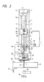
- Fig. 2 is a front view which schematically illustrates the condition where the wire is fed in the electric discharge machine.
- the electric discharge machine shapes a work 8 into a desired profile using a wire electrode 1.
- a head 10 that constitutes the electric discharge machine is provided with an automatic wire feeder.
- the work 8 is fastened by a cramp 22 onto a work table 21 mounted on a cross slide that is actuated by a servo motor through a servo mechanism.
- On the head 10 of the electric discharge machine is mounted a support member 9 that constitutes the automatic wire feeder, and under the head 10 is secured a support member 24 which mounts a support member 23 with an upper wire head 6 and rollers 18 that guide a feed pipe 5 and the wire electrode 1.
- a pair of guide rods 3 are arranged between the support member 9 and the support member 24. On these guide rods 3 is mounted a holder 20 to slide in the up and down directions.
- a feed pipe 5 that guides the wire electrode 1 using a screw 25 or the like, and are further mounted a thread guide 12, a pair of annealing rollers 4 with a feeder pin 17, and a pipe holder 13.
- the pair of annealing rollers 4 hold the wire electrode 1 that is fed through the thread guide 12 mounted on the holding member 20, and feeds it into the feed pipe 5, into a start hole 26 (see Fig. 1) formed in the work 8, and into a worked hole 27 (see Fig. 2) which is a narrow worked slit that will be described later and that is formed in the work 8 by the discharge machining.
- the annealing rollers 4 are provided with a feeder pin 17 for supplying an electric current to the wire electrode 1 via the annealing rollers 4.
- a direction changing roller 7 and a felt brake roller 11 On the support member 9 are mounted a direction changing roller 7 and a felt brake roller 11, and the wire electrode 1 is fed into the feed pipe 5 while a predetermined tension is given thereto.
- a slide rail 14 is fastened to the support member 24 mounted on the head 10 so that the feed pipe 5 can be smoothly slid.
- a cutter 16 is installed in the support member 24 under the slide rail 14 adjacent thereto.
- the cutter 16 cuts the wire electrode 1 to trim the tip of the wire electrode 1 so that the wire electrode will have a good tip. That is, the cutter 16 has a function to trim the tip of the wire electrode 1 so that it is inserted in the start hole 26 to machine the work 8 into a desired shape: the wire electrode 1 is then cut and its tip is trimmed so that it can be inserted in another start hole 26 or in the start hole 26 of another work.
- the cutter 16 functions to cut the tip of the wire electrode 1 and to remove it such that the wire electrode can be directly inserted in the machining hole, i.e., in the worked slit formed in the work 8 by the discharge machining that will be mentioned later at the time of inserting the wire electrode in the worked slit 27.
- the support member 24 fastened to the head 10 there are arranged a feeder pin 17, a pair of common rollers 15 for guiding the wire electrode 1 and a pair of rollers 18 under the cutter 16.
- the support member 23 that is fastened to the head 10 adjacent to the lower surface of the support member 24 is provided with a roller 18 for guiding the wire electrode 1, a pipe stopper 19 that prevents the feed pipe 5 from descending excessively (see Fig. 2), and an upper wire head 6.
- the upper wire head 6 is provided with a wire feeding port 6A, a die guide, an injection nozzle, a feeder terminal, and a feeder terminal holder.
- the electric discharge machine is provided with the lower wire head 35 which is opposed to the upper wire head 6, and on the downstream side of the lower wire head 35 is provided lead rollers 34 that pull out the wire electrode 1 to give tension thereto.
- the electric discharge machine which is constituted as described above operates in the following way.
- the wire electrode 1 has been wound on a source bobbin (see prior art of Fig. 8).
- the source bobbin is loaded to the electric discharge machine, and the wire electrode is delivered from the source bobbin by an automatic wire feeder.
- the automatic wire feeder usually has, as shown in Fig. 8, a wire running system which consists of various direction changing rollers, tension rollers 92, brake rollers 88, guide rollers, and lead rollers 93.
- a direction changing roller 2 is positioned on the downstream side of the brake roller 88 (see Fig.
- the wire electrode 1 successively passes through the direction changing roller 2, direction changing roller 7, felt brake roller 11, thread guide 12, a pair of annealing rollers 4, feed pipe 5, a pair of common rollers 15, and guide rollers 18, and is fed to the upper wire head 6, and reaches the discharge machining portion of the work 8.
- the wire electrode 1 passes through the discharge machining portion and the lower wire head 35, through the lead rollers, and through a winding roller 91 shown in Fig. 8, and is exhausted into the storage unit of wire electrode 1.
- the wire electrode 1 that is passed through the pair of common rollers 15 is once held by the annealing rollers 4 and the common rollers 15, a voltage is applied across the feeder pin 17 provided for the annealing rollers 4 and the feeder pin 17 provided for the common rollers 15 and a current is permitted to flow into the wire electrode 1 to anneal the wire electrode 1 so that it can be smoothly inserted in the start hole 26. Due to the annealing, the wire electrode 1 is softened and becomes free from internal stress such as twist and distortion; i.e., the wire electrode 1 is extended straight and is smoothly inserted in the start hole 26 or in the worked slit 27 that will be described later.
- Fig. 1 illustrates the case where the tip of the wire electrode 1 is cut and discarded in the electric discharge machine when the ordinary discharge machining is effected, i.e., when the work is machined into a predetermined profile or when the wire electrode is cut using a cutter 16 after having effected the discharge machining into a machining profile with the holder 20 being upwardly moved along the guide rods 3 and the lower end of the feed pipe 5 being positioned over the cutter 16 that is mounted on the support member 24.
- FIG. 2 illustrates the case where the wire electrode 1 is fed directly into the worked slit 27 formed in the work 8 by the discharge machining in the electric discharge machine when the wire electrode 1 is broken during the discharge machining of the work 8 into a predetermined machining profile or when the wire electrode 1 has been broken at the time of starting the discharge machining with the holder 20 being downwardly moved along the guide rods 3 and the lower end of the feed pipe 5 being positioned on the upper surface of a pipe stopper 19 mounted on the support member 24.
- Described below in conjunction with Figs. 3 and 4 is an operation for opening and closing the annealing rollers 4 in the electric discharge machine.
- one anneal roller 4 is provided in a fixed manner and is opposed to the feeder pin 17, and the other annealing roller 4 is allowed to be opened and closed.
- One annealing roller 4 is rotatably supported by a roller holder 4e fastened to the holder 20, and is in contact with the feeder pin 17 which supplies an electric current thereto.
- the other annealing roller 4 is rotatably supported by a roller holder 4a that is mounted on the holding member 20 to rotate with a shaft 4d as a center.
- the roller holder 4a is urged by a spring 4f toward a direction to separate away from the roller holder 4e. Therefore, the annealing rollers 4, 4 are usually under the condition to be separated away from each other by the force of a spring.
- the holder 20 is provided with an air cylinder 4c which works to reciprocally move a piston 4b which comes in contact with the roller holder 4a to rotate it with the shaft 4d as a center.
- the piston 4b is protruded by the action of the air cylinder 4c to turn the roller holder 4a, and whereby the annealing roller 4 rotatably supported by the roller holder 4a comes into contact with the opposing annealing roller 4 overcoming the force of the spring 4f such that the wire electrode 1 is held between the annealing rollers 4 and 4 as it runs passing therethrough.
- Figs. 5 and 6 Described below with reference to Figs. 5 and 6 is an operation for opening and closing the common rollers 15 and the cutter 16 in the electric discharge machine.
- the operation for opening and closing the cutter 16 is achieved using the same mechanism as that of the common rollers 15. Therefore, the following description deals with the operation for the common rollers 15 only.
- the device for opening and closing the common rollers 15 is so constituted as to open or close both common rollers 15 simultaneously.
- the pair of common rollers 15, 15 are rotatably supported by roller holders 38 secured to shafts 36 rotatably mounted on the support member 38.
- the feeder pin 17 is in contact with one common roller 15.
- the feeder pin 17 supplies an electric current to the common roller 15.
- a rotary lever 37 with a sector gear 37g To one shaft 36 is fastened a rotary lever 37 with a sector gear 37g, and to the other shaft 36 is fastened an L-shaped rotary lever 39 with a sector gear 39g, the sector gear 37g and the sector gear 39g being in mesh with each other.
- the support member 24 is provided with an air cylinder 15c which reciprocally moves a piston 15b.
- On and end of the piston 15b is rotatably mounted an end of the L-shaped rotary lever 3. Therefore, the piston 15b protrudes owing to the action of the air cylinder 15c and the L-shaped lever 39 rotates together with the shaft 36.
- Turn of the shaft 36 causes one roller holder 38 to rotate.
- the rotary lever 37 is rotated via the sector gear 37g and sector gear 39g.
- Turn of the rotary lever 37 causes the other roller holder 38 to rotate via the other shaft 36 with this shaft 36 as a center. Therefore, the common rollers 15, 15 that are rotatably supported by the roller holders 38 come into contact with each other and separate away from each other. When the common rollers 15, 15 come into contact with each other, the the electrode 1 running between the common rollers 15, 15 is held thereby.
- Figs. 1 to 6 that explain the electric discharge machine and in conjunction with Figs. 7(A) and 7(B) that are flow charts.
- This embodiment deals with the case where, when the wire electrode 1 is broken, a port for feeding the wire electrode 1 is slightly returned back from the point of breakage along the worked profile. It is, however, also allowable to insert the wire electrode 1 at a position where the wire electrode is broken without returning the wire electrode 1 back along the worked profile. In this case, the steps 64, 65, 80 and 81 should be omitted from the process that will be described later.
- the work 8 in which the start hole 26 is perforated by an aperture discharge machining apparatus or by a start hole machining apparatus is fastened onto a work table 21 by a clamp 22.
- a main switch, a motor and a servo motor in the electric discharge machine are turned on, and a controller is actuated to achieve the method of automatically feeding the wire to the electric discharge machine (step 40).
- the work table 21 is operated by the instruction from the controller and is so controlled that the wire feeding port 6A of the upper wire head 6 is located above the start hole 26 that is formed in the work 8. That is, the motor feed mechanism is actuated to adjust the position of the work table 21 on the cross slide, such that the wire electrode 1 is positioned, i.e., the wire feeding port 6A of the upper wire head 6 is positioned over the start hole 26 of the work 8 fastened to the work table 21. In this case, the feed pipe 5 is at a position shown in Fig. 1 (step 41).
- the wire electrode 1 is passed from the source bobbin through various rollers such as tension rollers and direction changing rollers, is fed into the feed pipe 5 via the direction changing rollers 2, 7, felt brake roller 11, thread guide 12, and anneal roller 4, and the tip of the wire electrode 1 is positioned to protrude beyond the lower end of the feed pipe 5 (steps 42, 43).
- various rollers such as tension rollers and direction changing rollers, is fed into the feed pipe 5 via the direction changing rollers 2, 7, felt brake roller 11, thread guide 12, and anneal roller 4, and the tip of the wire electrode 1 is positioned to protrude beyond the lower end of the feed pipe 5 (steps 42, 43).
- the pair of annealing rollers 4 provided on the holding member 20 are brought close to each other by actuating the roller opening/closing device, and the pair of common rollers 15 installed on the support member 24 are brought close to each other by actuating the roller opening/closing device, in order to hold predetermined portions of the wire electrode 1 (step 44).
- a voltage is applied across the feeder pin 17 provided for the annealing roller 4 and the feeder pin 17 provided for the common roller 15 to supply a current into the wire electrode 1 positioned between the annealing rollers 4 and the common rollers 15.
- the wire electrode 1 is annealed to remove internal stress possessed by the wire, and is extended to be straight (step 45).
- the cutter 16 installed on the downstream side of the feed pipe 5 but on the upstream side of the common rollers 15 is operated to cut the tip of the wire electrode 1 in order to trim the tip of the wire electrode 1 that is annealed, so that the wire electrode 1 is hanged vertically (step 46).
- the common rollers 15 that are close to each other are separated away from each other by actuating the roller opening/closing device so that the lower part of the wire electrode 1 is released.
- the automatic wire feeder is operated to feed the wire electrode 1, the holder 20 is lowered along the guide rods 3 until the lower end of the feed pipe 5 fastened to the holder 20 comes into contact with the pipe stopper 19 arranged on the upper wire head 6 as shown in Fig. 2, and the descending motion of the holder 20 is stopped at that position (step 47).
- the annealing rollers 4 are actuated to feed the wire electrode 1 in an attempt to insert the wire electrode 1 in the feed pipe 5 and in the start hole 26 in the work 8 from the wire feeding port 6A of the upper wire head 6 (step 48).
- step 49 It is detected and determined whether the operation by the controller has succeeded in inserting the wire electrode in the start hole 26 in the work 8.
- the process proceeds to a step 50 (step 49).
- the number N of tries for insertion is counted (step 51). It is judged whether the insertion be successful or not with the number N of tries for inserting the wire electrode 1 in the start hole 26 being a predetermined number N1 of times such as two times or less. In other words, it is judged whether N1 ⁇ N or not (step 52).
- the holder 20 or the feed pipe 5 is slightly lifted up and is lowered again to try the insertion again or the annealing rollers 4 are slightly rotated in the reverse direction to slightly lift up the wire electrode 1 and to lower it again in order to try the insertion when the number N of insertion tries is not greater than the predetermined number N2 of times, e.g., when N2 ⁇ N (step 52A).
- the holder 20 and the feed pipe 5 together are lifted up in order to cut off the tip of the wire electrode 1 and to trim the tip of the wire electrode 1, and the process is returned to the step 44 (step 52B).
- the process is returned back to the step 41 being based on the assumption that abnormal condition has developed such as worked scraps are clogging, the tip of the wire electrode 1 is bent, or the positioning is not effected correctly for the start hole 26.
- the wire electrode 1 is passed through the same start hole or is passed through another start hole when it is perforated in the same work 8.
- the operation is carried out to pass the wire electrode 1 in another start hole, it may be tried again to insert the wire electrode 1 in the start hole in which it could not be inserted (step 53).
- the annealing rollers 4 cease to feed the wire electrode 1 in compliance with the instruction from the controller, and the roller opening/closing device is actuated to separate the annealing rollers 4 away from each other in order to release the wire electrode (step 50).
- step 54 Thereafter, the holder 20 and the feed pipe 5 are moved up to a position shown in Fig. 1 to make it ready to machine the work 8 into a desired machining profile (step 54).
- the lead roller 34 arranged on the downstream side of the lower wire head 35 is actuated to draw the wire electrode (step 55).
- the wire running system in the automatic wire feeder is set to the wire feeding state, i.e., the guide rollers 18 are moved to their operation positions so as to guide the wire electrode 1, the lead roller 34 arranged on the downstream side of the lower wire head 35 is actuated to draw the wire electrode 1 which is then permitted to run to the machining portion of the work 8. Then, a voltage is applied across the work 8 and the wire electrode 1 such that electric discharge takes place (step 56), the work 8 is machined using the energy of electric discharge, and the work table 21 is actuated to move the wire electrode 1 and the work 8 relative to each other (step 57) so that the work 8 is machined into a predetermined machining profile.
- the breakage sensor 33 installed in the wire electrode 1 running system monitors the condition in which the wire electrode 1 is being fed.
- the wire electrode 1 that is broken is detected by the breakage sensor 33, and the detect signal is input to the controller.
- the controller judges whether the wire electrode 1 is being fed properly or is broken (step 58).
- the operation is continued to feed the wire electrode 1 and the work 8 is machined continuously into a predetermined machining profile (step 59).
- the controller judges whether the work 8 is machined by the wire electrode 1 into a predetermined machining profile or not. When the discharge machining into a predetermined machining profile has not been finished, the process returns back to the step 58 to carry out the above-mentioned processing again (step 60).
- the discharge machining is no more continued like the ordinary electric discharge machining. That is, the automatic wire feeder and the electric discharge machine are no more operated, the wire electrode 1 is cut like an ordinary operation to make it ready for carrying out the discharge machining into a next machining profile. That is, when the same work 8 is to be machined into another machining profile, the wire feeding port 6A of the upper wire head 6 is positioned on another start hole for achieving the machining profile. For this purpose, the process is returned back to the step 41.
- the work 8 is exchanged by another work (step 61).
- the following processing is carried out to insert the wire electrode again in the worked slit 27 which is the worked hole at a worked position of the work 8 of a worked profile without returning the wire feeding port 6A of the upper wire head 6 back to the start hole 26 from a position where the wire electrode was broken.
- the controller upon receipt of a detect signal sent from the breakage sensor 33 as a result of breakage of the wire electrode 1, the controller produces an instruction such that the automatic wire feeder no more feeds the wire electrode 1 (step 62), and actuates the lead roller 34 to draw the wire electrode 1 of the tip side that is broken or, in other words, to draw the wire electrode 1 that is worn out to send it to a predetermined worn wire electrode storage unit (step 63).
- the wire feeding port 6A of the upper wire head 6 which feeds the wire electrode 1 to the work 8 is moved back by a small distance such as about 0.3 mm along the worked profile of discharge machining. That is, the NC apparatus is actuated by the instruction from the controller to move the work table 21 relative to the wire feeding port 6A of the upper wire head 6 of wire electrode 1 along the worked profile (step 64).
- the work table 21 is stopped from moving the maintain the wire feeding port 6A of the wire head 6 at rest in an attempt to feed the wire electrode 1 to the worked slit 27 of a worked profile of the work 8.
- the wire electrode feeding port is opposed to the worked slit 27 of a worked profile at a point that is slightly returned back from a point where the wire electrode 1 was broken. Therefore, there is no need of adjusting their positions (step 65).
- the automatic wire feeder is actuated by the instruction from the controller to feed the wire electrode 1 through the feed pipe 5, and the tip of the wire electrode 1 is set to be protruded by a predetermined length beyond the lower end of the feed pipe 5 (steps 66, 67).
- the pair of annealing rollers installed on the holder 20 are brought close to each other by the roller opening/closing device, and the pair of common rollers 15 installed on the holder 24 are brought close to each other by the roller opening/closing device to hold predetermined portions of the wire electrode 1, respectively (step 68).
- a voltage is applied across the feeder pin 17 provided for the annealing roller 4 and the feeder pin 17 provided for the common roller 15 in order to flow an electric current into the wire electrode 1 between the annealing rollers 4 and the common rollers 15. That is, the wire electrode is annealed between the annealing rollers 4 and the common rollers 15; i.e., the wire electrode 1 is softened to remove its internal stress and is extended to become straight (step 69).
- the cutter 16 provided on the downstream side of the feed pipe 5 is actuated by the cutter operation device to cut and remove the tip of the wire electrode 1; i.e., the tip of the wire electrode 1 is trimmed (step 70).
- the roller opening/closing device is actuated to liberate the common rollers 15 from the closely arranged condition, the lower part of the wire electrode 1 is released from the held condition, the automatic wire feeder is actuated to feed the wire electrode 1, the holder 20 is lowered along the guide rods 3 until the lower end of the feed pipe 5 fastened to the holder 20 comes into contact with the pipe stopper 19 as shown in Fig. 2. The holder 20 is then stopped from descending at that position, and the annealing rollers 4 are actuated to feed the wire electrode 1 at a rate that meets the descending rate of the feed pipe 5 (step 71).
- the annealing rollers 4 are actuated to deliver the wire electrode 1, in an attempt to insert the wire electrode 1 from the feed pipe 5 and the wire feeding port 6A of the upper wire head 6 into the worked slit 27 of the work 8 at a point returned back from the point of breakage along the worked profile (step 72).
- the controller When the wire electrode 1 is not inserted in the worked slit 27 of the work 8, the number N of tries for insertion operation is counted and is input to the controller (step 74).
- the controller determines whether the number N of tries for inserting the wire electrode into the worked slit 27 is not greater than a predetermined number N3 of times, e.g., is not greater than five times to succeed in inserting the wire electrode in the worked slit. That is, the controller determines if N3 ⁇ N or not (step 75).
- the holder 20 or the feed pipe 5 is slightly moved up and is lowered again to try the insertion operation again, or the annealing rollers 4 are slightly rotated in the reverse direction to move the wire electrode 1 up in small amounts and is lowered again to try to insert the wire electrode 1 (step 75A).
- the tip of the wire electrode 1 is cut and is removed to trim the tip of the wire electrode 1.
- the holder 20 as well as the feed pipe 5 are upwardly moved, and the processing is returned back to the step 68 (step 75B).
- the number N of tries for inserting the wire electrode 1 in the worked slit 27 is greater than the predetermined number N3 of times, e.g., greater than five times, it is presumed that abnormal condition has developed such as the worked scraps are clogging, the tip of the wire electrode 1 is bent, or the set position is deviated relative to the worked slit 27, and the processing is returned back to the step 41.
- the wire electrode 1 is passed through the same start hole 26.
- another start hole is perforated in the same work 8
- the operation is carried out to pass the wire electrode 1 in the another start hole.
- step 76 When the operation is carried out to pass the wire electrode 1 in the another start hole, it may be tried again to insert the wire electrode 1 in the start hole 26 in which it could not be inserted or in the worked slit 27 after the predetermined machining profile has been obtained (step 76).
- the wire electrode 1 When the wire electrode 1 is inserted in the worked slit 27 of the work 8, the wire electrode 1 is no more fed by the annealing rollers 4 and is released from the held condition by separating the annealing rollers 4 from each other (step 77).
- the holder 20 and the feed pipe 5 are ascended to a position shown in Fig. 1 to make it ready to machine the work 8 into a predetermined machining profile (step 78).
- the lead roller 34 arranged on the downstream side of the lower wire head is actuated to hold the wire electrode 1 and to draw it (step 79).
- the wire running system in the automatic wire feeder is set to the wire feed condition, i.e., the guide rollers 18 are moved to their operation positions to guide the wire electrode 1, and the wire feeding port 6A of the upper wire head 6 that is feeding the wire electrode 1 to the work 8 is moved back by a small amount along the worked profile of discharge machining at the step 64. Therefore, the work table 21 is operated to return the wire electrode 1 back to the tip of worked slit of machining profile of the work 8, i.e., back to the working point of the work, such that the wire electrode 1 arrives at the working point (steps 80, 81).
- step 58 steps 82, 83
- the operation of discharge machining is returned back to the step 58 (steps 82, 83) in order to actuate the lead roller disposed on the downstream side of the lower wire head to draw the wire electrode 1, to feed or run the wire electrode 1 to the working portion of the work 8, to apply a voltage across the work 8 and the wire electrode 1 so that an electric discharge will take place enabling the work 8 to be discharge-machined utilizing the energy of the electric discharge, and to move the work table 21 thereby to move the wire electrode 1 and the work 8 relative to each other so that the work 8 is machined into a predetermined machining profile, in an attempt to machine the work 8 using the wire electrode 1.
- the aforementioned embodiment has dealt with the case where, when the wire electrode 1 is broken during the electric discharge machining, the wire feeding port 6A of the upper wire head 6 feeding the wire electrode 1 to the work 8 is slightly moved back along the worked profile of discharge machining. However, it is also allowable to try to insert the wire electrode 1 in the worked slit of a machining profile of the work at a position where the wire electrode was broken without moving the wire feeding port 6A of the upper wire head 6 back along the worked profile. In this case, the success rate for feeding the wire electrode 1 becomes slightly lower than that of the operation of the aforementioned embodiment.
Landscapes
- Chemical & Material Sciences (AREA)
- Chemical Kinetics & Catalysis (AREA)
- Electrochemistry (AREA)
- Engineering & Computer Science (AREA)
- Mechanical Engineering (AREA)
- Electrical Discharge Machining, Electrochemical Machining, And Combined Machining (AREA)
Description
- The present invention relates to a method of automatically feeding a wire to an electric discharge machine which effects the discharge machining to a work by giving an electric discharge energy between the work and a wire electrode.
- In a conventional electric discharge machine, for example, the work such as a super hard alloy and a hardened steel are machined using a portion where the wire electrode runs, and the wire is usually fed by an automatic wire feeding device. Conventional automatic wire feeding devices can be divided into those of a pipe guide system, those of a water stream guide system, and those of a start hole guide system.
- Fig. 9 illustrates an automatic wire feeder based on the start hole guide system. The automatic wire feeder according to the start hole guide system is achieved by positioning the wire feeder at a
start hole 26 formed in awork 8, penetrating a wire electrode through thestart hole 26 via awire feeder device 28, a feeder pipe and anupper guide 32, and pulling out thewire electrode 1 by the lead rollers located on the downstream side of alower guide 29. The start hole system has a merit in that the wire can be penetrated even when thestart hole 26 has a small diameter as well as a demerit in that the wire electrode itself must be composed of a hard wire. - Fig. 10 illustrates an automatic wire feeder based on the pipe guide system. The automatic wire feeder according to the pipe guide system is achieved by positioning the wire feeder at a
start hole 26 formed in thework 8, passing apipe 27 that works as a guide through thestart hole 26, actuating thewire feeder device 28 to pass thewire electrode 1 through thepipe 27, and pulling out thewire electrode 1 by the lead rollers positioned on the downstream side of thelower guide 29. The pipe guide system has a merit in that the feeding of wire electrode can be achieved maintaining a very high success rate as well as a demerit that thestart hole 26 must have a large diameter since thepipe 27 that serves as a guide must be passed through thestart hole 26. - Fig. 11 illustrates an automatic wire feeder based on the water stream guide system. The automatic wire feeder based on the water stream guide system is achieved by positioning the wire feeder at a
start hole 26 formed in thework 8, injecting a workingfluid 31 into thestart hole 26 through a workingfluid guide 30, passing thewire electrode 1 through thestart hole 26 that is fed by thewire feeder device 28 accompanying the force of injection of the workingfluid 31, and pulling out thewire electrode 1 by the lead rollers positioned at the downstream side of thelower guide 29. The water stream guide system has a problem in that the wire feeding is achieved at a very poor success rate. - According to the above-mentioned systems, however, in case the
wire electrode 1 is broken during the discharge machining, thewire electrode 1 is coupled together, i.e., the wire is automatically fed again by necessarily returning the procedure to thestart hole 26 which is the start point of machining. That is, feeding of thewire electrode 1 is achieved by moving the work table relative to the wire head to return the wire feeding portion of the wire head to thestart hole 26 formed in the work, passing thewire electrode 1 through thestart hole 26, and advancing thewire electrode 1 along the machining profile of thework 8 until it reaches the front end of discharge machining. That is, the wire feeding portion must be returned to thestart hole 26 every time when thewire electrode 1 breaks. Thewire electrode 1 that has passed through thestart hole 26 of thework 8 is then advanced along the worked profile that has been discharge machined until it reaches the point from where the machining is to be started. Therefore, the time is waisted and the discharge machining is not efficiently carried out. - GB-A-2066717 discloses a method of rethreading a wire electrode in an electric discharge machining apparatus when inserting a new workpiece, and is not specifically concerned with problems associated with rethreading of broken wire.
- A wire breakage detecting device has been proposed for use with the conventional electric discharge machines to detect the breakage of wire in case the wire electrode is broken when it is being fed during the discharge machining. For instance, a wire breakage detecting device used for an electric discharge machine has been disclosed in Japanese Utility Model Laid-Open No. 106128/1989 filed by the applicant of the present application. This wire breakage detecting device will now be briefly described with reference to Fig. 8. Breakage in a
wire electrode 1 is detected by a fiber-typephotoelectric sensor 85, and the machining power source is cut off in response to a breakage signal of the fiber-typephotoelectric sensor 85 to stop the electric discharge machining. Thesensor 85 is installed being opposed to a wire that serves as thewire electrode 1 positioned in the wire electrode feeding system, exhibits a function to detect breakage in the wire, and sends a breakage signal to a controller which cuts off the machining power source in response to the breakage signal to stop the electric discharge machining. Thesensor 85 may be installed at a position between aroller 87 on the upstream side of anupper wire head 86 and abrake roller 88 arranged on the upstream side of theroller 87 and where no deflection takes place in the wire that serves as thewire electrode 1. In addition to making it possible to smoothly carry out the operation of the electric discharge machine unattended, the automatic wire feeder makes it possible to automatically connect the wire together again even when it is broken during the machining, and exhibits a try-again function which tries to connect the wire together repetitively even when the feeding of wire results in failure until the wire is connected together. Thewire electrode 1 supplied from asource bobbin 89 by the automatic wire feeder passes through a variety of rollers, through a dies guide of awire head 86, subjected to discharge machining the work, passes through a dies guide of awire head 90 and rollers, taken up by a take-up roller 91, and is taken up by a take-up reel or is discharged onto a used wire storage unit. - Another wire breakage detecting device has been disclosed in Japanese Patent Application No. 221416/1988 that was filed by the applicant of the present application. The wire breakage detector device is arranged in the wire electrode running system that guides the wire electrode, and comprises a roller that rotates in response to the running of the wire electrode, a revolution sensor which is opposed to the roller to detect the number of revolutions of the roller, and a controller which detects whether the revolution signals of the roller as detected by the revolution sensor lie within a predetermined range or not, and which cuts off the machining power source in response to an abnormal signal in the detect signals to interrupt the machining of the work.
- Japanese Patent Publication No. 16771/1987 discloses a further line breakage detecting device which comprises a first detecting means for detecting an average value of peaks in the machining voltage, a second detecting means for detecting an instantaneous value of said machining voltage, and a comparator means which compares the value detected by the first detecting means with a value detected by the second detecting means, and which produces a signal for cutting off said power source when the instantaneous value becomes greater than the average peak value by more than a predetermined amount.
- An object of the present invention is to obviate or mitigate the problems of the prior art referred to above. The present invention provides in an electric discharge machine having wire feed means for continually feeding to a work station a wire electrode for machining a predetermined profile into a workpiece using the energy of electric discharge, a method of reinserting the wire electrode into the workpiece following breakage of the wire electrode,characterised by:
on detection of a breakage of the wire electrode, stopping relative movement of the wire electrode and the workpiece in the machining direction;
conditioning the broken end of the wire electrode on the feeding side of the breakage by supplying an electric current to the wire electrode thereby to anneal and hence straighten the wire electrode; and
guiding the annealed portion of the wire electrode through a worked slit of the workpiece at the point along the machined profile where the breakage was detected, or at a point displaced by a short distance along the machined profile in the reverse direction, i.e., at a position of the worked slit at the frontmost portion of machining for the workpiece by the wire electrode or at a position which is slightly displaced backwards from the point where the wire is broken along the machining profile without returning the wire feeding port of the wire head back to the position of start hole that is perforated in advance in the work. Therefore, the discharge machining is executed again by the wire electrode for the work contributing to greatly improving the machining efficiency. - The present invention may provide a method of automatically feeding wire to automatically feed a wire electrode to the machining hole of a workpiece, wherein an electric current is permitted to flow into the wire electrode to anneal it in order to remove internal stress existing in the wire electrode prior to passing the wire electrode through the worked gap formed in the work, the wire electrode is elongated into a straight form, and the wire electrode is passed through the worked gap of the work easily and quickly. That is, a feeder pipe is lowered down to the wire feeding port of the upper wire head, the feeder pipe containing passing therethrough the wire electrode that was annealed and elongated by supplying a current thereto through feeder pins provided for the anneal rollers and common rollers. Therefore, the tip of the wire electrode is exposed only slightly, and the wire electrode downwardly extends straight. The wire electrode is lowered by the wire feed rollers toward the worked gap of a machining profile of the workpiece at a point where the wire is broken, and is permitted to pass through smoothly, reliably and quickly.
- One embodiment of the present invention provides a method of automatically feeding wire to an electric discharge machine comprising:
a step for stopping the relative movement of a work table and a wire head in response to a break signal of the wire electrode produced by a wire breakage sensor during the electric discharge machining;
a step for taking up the wire electrode of the broken side to remove it, and for annealing the wire electrode of the feeding side to extend the wire electrode straight;
a step for cutting the tip of the wire electrode to remove it;
a step for feeding said wire electrode and lowering a feed pipe down to a predetermined position;
a step for actuating a wire feed roller to insert said wire electrode in a worked slit which is a worked hole of a machining profile at a point where the wire is broken in the work; and
a step for pulling out said wire electrode that has passed through said worked slit using the lead rollers. - Another embodiment of the present invention provides a method of automatically feeding a wire to an electric discharge machine comprising:
a step for stopping the relative movement of a work table and a wire head in response to a break signal of the wire electrode produced by a wire breakage sensor during the electric discharge machining;
a step for taking up the wire of the broken side to remove it, and for annealing the wire of the feeding side to extend the wire electrode;
a step for cutting the tip of the wire electrode to remove it;
a step for feeding said wire electrode and lowering a feed pipe down to a predetermined position;
a step for slightly moving back the wire feeding port of said wire head from the worked hole or from the worked slit where the wire is broken along the worked profile;
a step for actuating a wire feed roller to insert said wire electrode ina worked slit of a machining profile;
a step for inserting said wire electrode that has passed through said worked hole in a lead roller; and
a step for advancing said wire electrode to a discharge machining portion along the worked profile, i.e., along the worked slit. - A third embodiment of the present invention provides a method of automatically feeding a wire to an electric discharge machine wherein an electric current is supplied to a wire electrode through feeder pins provided for the annealing rollers and for the common rollers in order to anneal the wire electrode of the feeding side and to extend said wire electrode, such that the feed pipe of said wire electrode is lowered down to the wire head, and wherein said annealing roller is driven to slowly feed said wire electrode and to insert said wire electrode in the worked slit of a machining profile at which the wire is broken in the work, and said wire electrode is extended straight such that said wire electrode is inserted in said machining hole reliably and quickly even when the worked slit is narrow at a point where the wire is broken in the work.
- A fourth embodiment of the present invention provides a method of automatically feeding a wire to an electric discharge machine wherein a wire feeding port of a wire head is slightly moved back from the worked slit where the wire is broken along a worked profile, and the wire feed rollers are driven to pass the wire electrode through the worked slit of a machining profile, such that the end of said wire electrode is not impaired by the edge of the work at which the wire is broken and that the wire electrode can be smoothly inserted in the worked hole or in the worked slit contributing to greatly improving the success rate of the wire feeding or wire connection. That is, the wire feeding port of the wire head is set at a position slightly returned back, e.g., returned back by about 0.3 mm from the worked hole at which the wire is broken along the worked profile, and the annealing rollers are driven to pass said wire electrode in the worked hole of the machining profile. Therefore, the tip of the wire electrode is not impaired by the edge of the work at which the wire is broken, and the wire electrode is smoothly inserted in the worked hole or in the worked slit contributing to greatly improving the success rate of wire feeding or wire connection.
- When the wire electrode is broken during the discharge machining by the electric discharge machine, the broken wire electrode is resorted by a conventional automatic wire feeder by returning the procedure back to the start hole, i.e., by returning the procedure back to the working point along the worked profile that has been discharge machined already. According to the method of automatically feeding the wire, on the other hand, the broken wire is restored by feeding the wire electrode to the point where the wire is broken or to the worked hole at a point slightly returned back from the point where the wire is broken. Therefore, the broken wire is restored within very short period of time and reliably, making it possible to greatly improve the efficiency for automatically feeding the wire or for electric discharge machining. Furthermore, the wire is automatically fed by an NC apparatus, and the electric discharge machine is controlled nonattended.
- For a better understanding of the present invention and to show how the same may be carried into effect, reference will now be made, by way of example, to the accompanying drawings in which:-
- Fig. 1 is a front view illustrating an embodiment of an electric discharge machine for achieving the method of automatically feeding wire according to the present invention;
- Fig. 2 is a schematic front view illustrating the steps for automatically feeding the wire in Fig. 1;
- Fig. 3 is a diagram explaining on an enlarged scale a portion where the annealing rollers of Fig. 1 are located;
- Fig. 4 is a diagram illustrating a device for opening and closing the annealing rollers of Fig. 3;
- Fig. 5 is a diagram illustrating on an enlarged scale the portions where common rollers and cutter of Fig. 1 are located;
- Fig. 6 is a diagram explaining a device for opening and closing the common rollers of Fig. 5;
- Figs. 7(A) and 7(B) are flow charts for explaining the operations for achieving the method of automatically feeding wire according to the present invention;
- Fig. 8 is a diagram which schematically illustrates a wire breakage detecting device in a conventional electric discharge machine;
- Fig. 9 is a diagram which schematically illustrates a start hole system in a conventional method of automatically feeding wire;
- Fig. 10 is a diagram which schematically illustrates a pipe guide system in a conventional method of automatically feeding wire; and
- Fig. 11 is a diagram which schematically illustrates a water stream guide system in a conventional method of automatically feeding wire.
- Described below in conjunction with the drawings is a method of automatically supplying wire to an electric discharge machine according to an embodiment of the present invention.
- Fig. 1 is a front view illustrating an electric discharge machine for achieving the method of automatically feeding wire according to the present invention, and Fig. 2 is a front view which schematically illustrates the condition where the wire is fed in the electric discharge machine.
- The electric discharge machine shapes a
work 8 into a desired profile using awire electrode 1. Ahead 10 that constitutes the electric discharge machine is provided with an automatic wire feeder. Thework 8 is fastened by acramp 22 onto a work table 21 mounted on a cross slide that is actuated by a servo motor through a servo mechanism. On thehead 10 of the electric discharge machine is mounted asupport member 9 that constitutes the automatic wire feeder, and under thehead 10 is secured asupport member 24 which mounts asupport member 23 with anupper wire head 6 androllers 18 that guide afeed pipe 5 and thewire electrode 1. A pair ofguide rods 3 are arranged between thesupport member 9 and thesupport member 24. On theseguide rods 3 is mounted aholder 20 to slide in the up and down directions. Onto theholder 20 is fastened afeed pipe 5 that guides thewire electrode 1 using ascrew 25 or the like, and are further mounted athread guide 12, a pair ofannealing rollers 4 with afeeder pin 17, and apipe holder 13. The pair ofannealing rollers 4 hold thewire electrode 1 that is fed through thethread guide 12 mounted on the holdingmember 20, and feeds it into thefeed pipe 5, into a start hole 26 (see Fig. 1) formed in thework 8, and into a worked hole 27 (see Fig. 2) which is a narrow worked slit that will be described later and that is formed in thework 8 by the discharge machining. Theannealing rollers 4 are provided with afeeder pin 17 for supplying an electric current to thewire electrode 1 via theannealing rollers 4. On thesupport member 9 are mounted adirection changing roller 7 and a feltbrake roller 11, and thewire electrode 1 is fed into thefeed pipe 5 while a predetermined tension is given thereto. Further, aslide rail 14 is fastened to thesupport member 24 mounted on thehead 10 so that thefeed pipe 5 can be smoothly slid. Acutter 16 is installed in thesupport member 24 under theslide rail 14 adjacent thereto. - The
cutter 16 cuts thewire electrode 1 to trim the tip of thewire electrode 1 so that the wire electrode will have a good tip. That is, thecutter 16 has a function to trim the tip of thewire electrode 1 so that it is inserted in thestart hole 26 to machine thework 8 into a desired shape: thewire electrode 1 is then cut and its tip is trimmed so that it can be inserted in anotherstart hole 26 or in thestart hole 26 of another work. In addition to the above-mentioned function, thecutter 16 functions to cut the tip of thewire electrode 1 and to remove it such that the wire electrode can be directly inserted in the machining hole, i.e., in the worked slit formed in thework 8 by the discharge machining that will be mentioned later at the time of inserting the wire electrode in the worked slit 27. - In the
support member 24 fastened to thehead 10, there are arranged afeeder pin 17, a pair ofcommon rollers 15 for guiding thewire electrode 1 and a pair ofrollers 18 under thecutter 16. Further, thesupport member 23 that is fastened to thehead 10 adjacent to the lower surface of thesupport member 24 is provided with aroller 18 for guiding thewire electrode 1, apipe stopper 19 that prevents thefeed pipe 5 from descending excessively (see Fig. 2), and anupper wire head 6. Though not specifically described, theupper wire head 6 is provided with awire feeding port 6A, a die guide, an injection nozzle, a feeder terminal, and a feeder terminal holder. The electric discharge machine is provided with thelower wire head 35 which is opposed to theupper wire head 6, and on the downstream side of thelower wire head 35 is providedlead rollers 34 that pull out thewire electrode 1 to give tension thereto. - The electric discharge machine which is constituted as described above operates in the following way. The
wire electrode 1 has been wound on a source bobbin (see prior art of Fig. 8). The source bobbin is loaded to the electric discharge machine, and the wire electrode is delivered from the source bobbin by an automatic wire feeder. In order to feed thewire electrode 1 delivered from thesource bobbin 89 to the discharge machining portion, the automatic wire feeder usually has, as shown in Fig. 8, a wire running system which consists of various direction changing rollers,tension rollers 92,brake rollers 88, guide rollers, and leadrollers 93. With regard to the electric discharge machine as shown in Fig. 1, adirection changing roller 2 is positioned on the downstream side of the brake roller 88 (see Fig. 8) in the wire running system. Thewire electrode 1 successively passes through thedirection changing roller 2,direction changing roller 7, feltbrake roller 11,thread guide 12, a pair ofannealing rollers 4,feed pipe 5, a pair ofcommon rollers 15, and guiderollers 18, and is fed to theupper wire head 6, and reaches the discharge machining portion of thework 8. Next, thewire electrode 1 passes through the discharge machining portion and thelower wire head 35, through the lead rollers, and through a windingroller 91 shown in Fig. 8, and is exhausted into the storage unit ofwire electrode 1. - Prior to inserting the
wire electrode 1 in the hole such asstart hole 26, thewire electrode 1 that is passed through the pair ofcommon rollers 15 is once held by theannealing rollers 4 and thecommon rollers 15, a voltage is applied across thefeeder pin 17 provided for theannealing rollers 4 and thefeeder pin 17 provided for thecommon rollers 15 and a current is permitted to flow into thewire electrode 1 to anneal thewire electrode 1 so that it can be smoothly inserted in thestart hole 26. Due to the annealing, thewire electrode 1 is softened and becomes free from internal stress such as twist and distortion; i.e., thewire electrode 1 is extended straight and is smoothly inserted in thestart hole 26 or in the worked slit 27 that will be described later. - Fig. 1 illustrates the case where the tip of the
wire electrode 1 is cut and discarded in the electric discharge machine when the ordinary discharge machining is effected, i.e., when the work is machined into a predetermined profile or when the wire electrode is cut using acutter 16 after having effected the discharge machining into a machining profile with theholder 20 being upwardly moved along theguide rods 3 and the lower end of thefeed pipe 5 being positioned over thecutter 16 that is mounted on thesupport member 24. Fig. 2 illustrates the case where thewire electrode 1 is fed directly into the worked slit 27 formed in thework 8 by the discharge machining in the electric discharge machine when thewire electrode 1 is broken during the discharge machining of thework 8 into a predetermined machining profile or when thewire electrode 1 has been broken at the time of starting the discharge machining with theholder 20 being downwardly moved along theguide rods 3 and the lower end of thefeed pipe 5 being positioned on the upper surface of apipe stopper 19 mounted on thesupport member 24. - Described below in conjunction with Figs. 3 and 4 is an operation for opening and closing the
annealing rollers 4 in the electric discharge machine. With reference to a device for opening and closing theannealing rollers 4 as shown, oneanneal roller 4 is provided in a fixed manner and is opposed to thefeeder pin 17, and theother annealing roller 4 is allowed to be opened and closed. Oneannealing roller 4 is rotatably supported by aroller holder 4e fastened to theholder 20, and is in contact with thefeeder pin 17 which supplies an electric current thereto. Theother annealing roller 4 is rotatably supported by aroller holder 4a that is mounted on the holdingmember 20 to rotate with ashaft 4d as a center. Theroller holder 4a is urged by a spring 4f toward a direction to separate away from theroller holder 4e. Therefore, theannealing rollers holder 20 is provided with anair cylinder 4c which works to reciprocally move apiston 4b which comes in contact with theroller holder 4a to rotate it with theshaft 4d as a center. Therefore, thepiston 4b is protruded by the action of theair cylinder 4c to turn theroller holder 4a, and whereby theannealing roller 4 rotatably supported by theroller holder 4a comes into contact with the opposingannealing roller 4 overcoming the force of the spring 4f such that thewire electrode 1 is held between theannealing rollers - Described below with reference to Figs. 5 and 6 is an operation for opening and closing the
common rollers 15 and thecutter 16 in the electric discharge machine. Here, the operation for opening and closing thecutter 16 is achieved using the same mechanism as that of thecommon rollers 15. Therefore, the following description deals with the operation for thecommon rollers 15 only. As shown, the device for opening and closing thecommon rollers 15 is so constituted as to open or close bothcommon rollers 15 simultaneously. The pair ofcommon rollers roller holders 38 secured toshafts 36 rotatably mounted on thesupport member 38. Thefeeder pin 17 is in contact with onecommon roller 15. Thefeeder pin 17 supplies an electric current to thecommon roller 15. To oneshaft 36 is fastened arotary lever 37 with asector gear 37g, and to theother shaft 36 is fastened an L-shapedrotary lever 39 with asector gear 39g, thesector gear 37g and thesector gear 39g being in mesh with each other. Thesupport member 24 is provided with anair cylinder 15c which reciprocally moves apiston 15b. On and end of thepiston 15b is rotatably mounted an end of the L-shapedrotary lever 3. Therefore, thepiston 15b protrudes owing to the action of theair cylinder 15c and the L-shapedlever 39 rotates together with theshaft 36. Turn of theshaft 36 causes oneroller holder 38 to rotate. Accompanying the turn of the L-shapedrotary lever 39, therotary lever 37 is rotated via thesector gear 37g andsector gear 39g. Turn of therotary lever 37 causes theother roller holder 38 to rotate via theother shaft 36 with thisshaft 36 as a center. Therefore, thecommon rollers roller holders 38 come into contact with each other and separate away from each other. When thecommon rollers electrode 1 running between thecommon rollers - Described below is a method of automatically feeding wire to the electric discharge machine according to an embodiment of the present invention in conjunction with Figs. 1 to 6 that explain the electric discharge machine and in conjunction with Figs. 7(A) and 7(B) that are flow charts. This embodiment deals with the case where, when the
wire electrode 1 is broken, a port for feeding thewire electrode 1 is slightly returned back from the point of breakage along the worked profile. It is, however, also allowable to insert thewire electrode 1 at a position where the wire electrode is broken without returning thewire electrode 1 back along the worked profile. In this case, thesteps - First, in order to machine the
work 8 by the electric discharge machine, thework 8 in which thestart hole 26 is perforated by an aperture discharge machining apparatus or by a start hole machining apparatus is fastened onto a work table 21 by aclamp 22. A main switch, a motor and a servo motor in the electric discharge machine are turned on, and a controller is actuated to achieve the method of automatically feeding the wire to the electric discharge machine (step 40). - The work table 21 is operated by the instruction from the controller and is so controlled that the
wire feeding port 6A of theupper wire head 6 is located above thestart hole 26 that is formed in thework 8. That is, the motor feed mechanism is actuated to adjust the position of the work table 21 on the cross slide, such that thewire electrode 1 is positioned, i.e., thewire feeding port 6A of theupper wire head 6 is positioned over thestart hole 26 of thework 8 fastened to the work table 21. In this case, thefeed pipe 5 is at a position shown in Fig. 1 (step 41). - Owing to the operation of the automatic wire feeder, the
wire electrode 1 is passed from the source bobbin through various rollers such as tension rollers and direction changing rollers, is fed into thefeed pipe 5 via thedirection changing rollers brake roller 11,thread guide 12, andanneal roller 4, and the tip of thewire electrode 1 is positioned to protrude beyond the lower end of the feed pipe 5 (steps 42, 43). - The pair of
annealing rollers 4 provided on the holdingmember 20 are brought close to each other by actuating the roller opening/closing device, and the pair ofcommon rollers 15 installed on thesupport member 24 are brought close to each other by actuating the roller opening/closing device, in order to hold predetermined portions of the wire electrode 1 (step 44). - A voltage is applied across the
feeder pin 17 provided for theannealing roller 4 and thefeeder pin 17 provided for thecommon roller 15 to supply a current into thewire electrode 1 positioned between theannealing rollers 4 and thecommon rollers 15. Thewire electrode 1 is annealed to remove internal stress possessed by the wire, and is extended to be straight (step 45). - The
cutter 16 installed on the downstream side of thefeed pipe 5 but on the upstream side of thecommon rollers 15 is operated to cut the tip of thewire electrode 1 in order to trim the tip of thewire electrode 1 that is annealed, so that thewire electrode 1 is hanged vertically (step 46). - Then, upon instruction from the controller, the
common rollers 15 that are close to each other are separated away from each other by actuating the roller opening/closing device so that the lower part of thewire electrode 1 is released. Then, the automatic wire feeder is operated to feed thewire electrode 1, theholder 20 is lowered along theguide rods 3 until the lower end of thefeed pipe 5 fastened to theholder 20 comes into contact with thepipe stopper 19 arranged on theupper wire head 6 as shown in Fig. 2, and the descending motion of theholder 20 is stopped at that position (step 47). - The
annealing rollers 4 are actuated to feed thewire electrode 1 in an attempt to insert thewire electrode 1 in thefeed pipe 5 and in thestart hole 26 in thework 8 from thewire feeding port 6A of the upper wire head 6 (step 48). - It is detected and determined whether the operation by the controller has succeeded in inserting the wire electrode in the
start hole 26 in thework 8. When thewire electrode 1 is inserted in thestart hole 26 of thework 8, the process proceeds to a step 50 (step 49). - When the
wire electrode 1 is not inserted in thestart hole 26 of thework 8, the number N of tries for insertion is counted (step 51). It is judged whether the insertion be successful or not with the number N of tries for inserting thewire electrode 1 in thestart hole 26 being a predetermined number N₁ of times such as two times or less. In other words, it is judged whether N₁≧N or not (step 52). - When the operation for inserting the
wire electrode 1 has resulted in failure, theholder 20 or thefeed pipe 5 is slightly lifted up and is lowered again to try the insertion again or theannealing rollers 4 are slightly rotated in the reverse direction to slightly lift up thewire electrode 1 and to lower it again in order to try the insertion when the number N of insertion tries is not greater than the predetermined number N₂ of times, e.g., when N₂≧N (step 52A). However, when thewire electrode 1 is inserted with the number N of insertion tries being greater than the predetermined number N₂ of times but smaller than a predetermined number N₁ of times, i.e., N₁≧ N>N₂, theholder 20 and thefeed pipe 5 together are lifted up in order to cut off the tip of thewire electrode 1 and to trim the tip of thewire electrode 1, and the process is returned to the step 44 (step 52B). - When the number N of tries for inserting the
wire electrode 1 in thestart hole 26 is greater than the predetermined number N₁ of times, e.g., greater than five times, the process is returned back to thestep 41 being based on the assumption that abnormal condition has developed such as worked scraps are clogging, the tip of thewire electrode 1 is bent, or the positioning is not effected correctly for thestart hole 26. In this case, thewire electrode 1 is passed through the same start hole or is passed through another start hole when it is perforated in thesame work 8. When the operation is carried out to pass thewire electrode 1 in another start hole, it may be tried again to insert thewire electrode 1 in the start hole in which it could not be inserted (step 53). - When the
wire electrode 1 is inserted in thestart hole 26 of thework 8, i.e., when the controller receives a signal that is produced under the condition where thewire electrode 1 is held by thelead roller 34 on the downstream side of the lower wire head or receives a signal that is produced under the condition where thebreakage sensor 33 detects the tensed state of thewire electrode 1 that is drawn by thelead roller 34, theannealing rollers 4 cease to feed thewire electrode 1 in compliance with the instruction from the controller, and the roller opening/closing device is actuated to separate theannealing rollers 4 away from each other in order to release the wire electrode (step 50). - Thereafter, the
holder 20 and thefeed pipe 5 are moved up to a position shown in Fig. 1 to make it ready to machine thework 8 into a desired machining profile (step 54). - The
lead roller 34 arranged on the downstream side of thelower wire head 35 is actuated to draw the wire electrode (step 55). - The wire running system in the automatic wire feeder is set to the wire feeding state, i.e., the
guide rollers 18 are moved to their operation positions so as to guide thewire electrode 1, thelead roller 34 arranged on the downstream side of thelower wire head 35 is actuated to draw thewire electrode 1 which is then permitted to run to the machining portion of thework 8. Then, a voltage is applied across thework 8 and thewire electrode 1 such that electric discharge takes place (step 56), thework 8 is machined using the energy of electric discharge, and the work table 21 is actuated to move thewire electrode 1 and thework 8 relative to each other (step 57) so that thework 8 is machined into a predetermined machining profile. - When the
work 8 is being machined by the electric discharge machine, thebreakage sensor 33 installed in thewire electrode 1 running system monitors the condition in which thewire electrode 1 is being fed. Thewire electrode 1 that is broken is detected by thebreakage sensor 33, and the detect signal is input to the controller. Upon receipt of a detect signal from thebreakage sensor 33, the controller judges whether thewire electrode 1 is being fed properly or is broken (step 58). - As far as the
wire electrode 1 is not broken, the operation is continued to feed thewire electrode 1 and thework 8 is machined continuously into a predetermined machining profile (step 59). - The controller judges whether the
work 8 is machined by thewire electrode 1 into a predetermined machining profile or not. When the discharge machining into a predetermined machining profile has not been finished, the process returns back to thestep 58 to carry out the above-mentioned processing again (step 60). - When the
work 8 has been machined by thewire electrode 1 into a predetermined machining profile, the discharge machining is no more continued like the ordinary electric discharge machining. That is, the automatic wire feeder and the electric discharge machine are no more operated, thewire electrode 1 is cut like an ordinary operation to make it ready for carrying out the discharge machining into a next machining profile. That is, when thesame work 8 is to be machined into another machining profile, thewire feeding port 6A of theupper wire head 6 is positioned on another start hole for achieving the machining profile. For this purpose, the process is returned back to thestep 41. When thesame work 8 is not to be machined into another machining profile, thework 8 is exchanged by another work (step 61). - When the
wire electrode 1 that is broken is detected by thebreakage sensor 33 at thestep 58, the following processing is carried out to insert the wire electrode again in the worked slit 27 which is the worked hole at a worked position of thework 8 of a worked profile without returning thewire feeding port 6A of theupper wire head 6 back to thestart hole 26 from a position where the wire electrode was broken. That is, upon receipt of a detect signal sent from thebreakage sensor 33 as a result of breakage of thewire electrode 1, the controller produces an instruction such that the automatic wire feeder no more feeds the wire electrode 1 (step 62), and actuates thelead roller 34 to draw thewire electrode 1 of the tip side that is broken or, in other words, to draw thewire electrode 1 that is worn out to send it to a predetermined worn wire electrode storage unit (step 63). - Upon receipt of the instruction from the controller, the
wire feeding port 6A of theupper wire head 6 which feeds thewire electrode 1 to thework 8 is moved back by a small distance such as about 0.3 mm along the worked profile of discharge machining. That is, the NC apparatus is actuated by the instruction from the controller to move the work table 21 relative to thewire feeding port 6A of theupper wire head 6 ofwire electrode 1 along the worked profile (step 64). - Then, the work table 21 is stopped from moving the maintain the
wire feeding port 6A of thewire head 6 at rest in an attempt to feed thewire electrode 1 to the worked slit 27 of a worked profile of thework 8. Under this condition, the wire electrode feeding port is opposed to the worked slit 27 of a worked profile at a point that is slightly returned back from a point where thewire electrode 1 was broken. Therefore, there is no need of adjusting their positions (step 65). - Next, the automatic wire feeder is actuated by the instruction from the controller to feed the
wire electrode 1 through thefeed pipe 5, and the tip of thewire electrode 1 is set to be protruded by a predetermined length beyond the lower end of the feed pipe 5 (steps 66, 67). - Upon receipt of an instruction from the controller, the pair of annealing rollers installed on the
holder 20 are brought close to each other by the roller opening/closing device, and the pair ofcommon rollers 15 installed on theholder 24 are brought close to each other by the roller opening/closing device to hold predetermined portions of thewire electrode 1, respectively (step 68). - In response to an instruction from the controller, a voltage is applied across the
feeder pin 17 provided for theannealing roller 4 and thefeeder pin 17 provided for thecommon roller 15 in order to flow an electric current into thewire electrode 1 between theannealing rollers 4 and thecommon rollers 15. That is, the wire electrode is annealed between theannealing rollers 4 and thecommon rollers 15; i.e., thewire electrode 1 is softened to remove its internal stress and is extended to become straight (step 69). - Then, the
cutter 16 provided on the downstream side of thefeed pipe 5 is actuated by the cutter operation device to cut and remove the tip of thewire electrode 1; i.e., the tip of thewire electrode 1 is trimmed (step 70). - In response to an instruction from the controller, the roller opening/closing device is actuated to liberate the
common rollers 15 from the closely arranged condition, the lower part of thewire electrode 1 is released from the held condition, the automatic wire feeder is actuated to feed thewire electrode 1, theholder 20 is lowered along theguide rods 3 until the lower end of thefeed pipe 5 fastened to theholder 20 comes into contact with thepipe stopper 19 as shown in Fig. 2. Theholder 20 is then stopped from descending at that position, and theannealing rollers 4 are actuated to feed thewire electrode 1 at a rate that meets the descending rate of the feed pipe 5 (step 71). - The
annealing rollers 4 are actuated to deliver thewire electrode 1, in an attempt to insert thewire electrode 1 from thefeed pipe 5 and thewire feeding port 6A of theupper wire head 6 into the worked slit 27 of thework 8 at a point returned back from the point of breakage along the worked profile (step 72). - It is detected and determined whether the
wire electrode 1 is inserted in the worked slit of a machining profile of thework 8 or not. That is, when thewire electrode 1 is inserted in the worked slit 27 of thework 8, thelead roller 34 grips thewire electrode 1 to draw it. Therefore, the condition in which thelead roller 34 delivers thewire electrode 1 is detected, and the controller proceeds the processing toward a step 77 (step 73) in response to the detect signal. - When the
wire electrode 1 is not inserted in the worked slit 27 of thework 8, the number N of tries for insertion operation is counted and is input to the controller (step 74). - The controller determines whether the number N of tries for inserting the wire electrode into the worked slit 27 is not greater than a predetermined number N₃ of times, e.g., is not greater than five times to succeed in inserting the wire electrode in the worked slit. That is, the controller determines if N₃≧N or not (step 75).
- When the try for inserting the
wire electrode 1 has resulted in failure with the number N of tries being not greater than a predetermined number N₄ of times, e.g., not greater than two times, i.e., N₄≧N, theholder 20 or thefeed pipe 5 is slightly moved up and is lowered again to try the insertion operation again, or theannealing rollers 4 are slightly rotated in the reverse direction to move thewire electrode 1 up in small amounts and is lowered again to try to insert the wire electrode 1 (step 75A). However, when thewire electrode 1 is not inserted in the worked slit 27 despite the try for inserting the wire electrode is repeated the predetermined number N₄ of times but is inserted after the insertion operation is tried more than the above-mentioned number of times which is not greater than a predetermined number of times N₃, i.e., N₃≧N≧N₄, the tip of thewire electrode 1 is cut and is removed to trim the tip of thewire electrode 1. For this purpose, theholder 20 as well as thefeed pipe 5 are upwardly moved, and the processing is returned back to the step 68 (step 75B). - When the number N of tries for inserting the
wire electrode 1 in the worked slit 27 is greater than the predetermined number N₃ of times, e.g., greater than five times, it is presumed that abnormal condition has developed such as the worked scraps are clogging, the tip of thewire electrode 1 is bent, or the set position is deviated relative to the worked slit 27, and the processing is returned back to thestep 41. In this case, thewire electrode 1 is passed through thesame start hole 26. Or, when another start hole is perforated in thesame work 8, the operation is carried out to pass thewire electrode 1 in the another start hole. When the operation is carried out to pass thewire electrode 1 in the another start hole, it may be tried again to insert thewire electrode 1 in thestart hole 26 in which it could not be inserted or in the worked slit 27 after the predetermined machining profile has been obtained (step 76). - When the
wire electrode 1 is inserted in the worked slit 27 of thework 8, thewire electrode 1 is no more fed by theannealing rollers 4 and is released from the held condition by separating theannealing rollers 4 from each other (step 77). - The
holder 20 and thefeed pipe 5 are ascended to a position shown in Fig. 1 to make it ready to machine thework 8 into a predetermined machining profile (step 78). - The
lead roller 34 arranged on the downstream side of the lower wire head is actuated to hold thewire electrode 1 and to draw it (step 79). - The wire running system in the automatic wire feeder is set to the wire feed condition, i.e., the
guide rollers 18 are moved to their operation positions to guide thewire electrode 1, and thewire feeding port 6A of theupper wire head 6 that is feeding thewire electrode 1 to thework 8 is moved back by a small amount along the worked profile of discharge machining at thestep 64. Therefore, the work table 21 is operated to return thewire electrode 1 back to the tip of worked slit of machining profile of thework 8, i.e., back to the working point of the work, such that thewire electrode 1 arrives at the working point (steps 80, 81). - The operation of discharge machining is returned back to the step 58 (
steps 82, 83) in order to actuate the lead roller disposed on the downstream side of the lower wire head to draw thewire electrode 1, to feed or run thewire electrode 1 to the working portion of thework 8, to apply a voltage across thework 8 and thewire electrode 1 so that an electric discharge will take place enabling thework 8 to be discharge-machined utilizing the energy of the electric discharge, and to move the work table 21 thereby to move thewire electrode 1 and thework 8 relative to each other so that thework 8 is machined into a predetermined machining profile, in an attempt to machine thework 8 using thewire electrode 1. - The aforementioned embodiment has dealt with the case where, when the
wire electrode 1 is broken during the electric discharge machining, thewire feeding port 6A of theupper wire head 6 feeding thewire electrode 1 to thework 8 is slightly moved back along the worked profile of discharge machining. However, it is also allowable to try to insert thewire electrode 1 in the worked slit of a machining profile of the work at a position where the wire electrode was broken without moving thewire feeding port 6A of theupper wire head 6 back along the worked profile. In this case, the success rate for feeding thewire electrode 1 becomes slightly lower than that of the operation of the aforementioned embodiment.
Claims (13)
- In an electric discharge machine having wire feed means for continually feeding to a work station(21) a wire electrode(1) for machining a predetermined profile into a workpiece(8) using the energy of electric discharge, a method of reinserting the wire electrode(1) into the workpiece(8) following breakage of the wire electrode(1) characterised by:
on detection of a breakage of the wire electrode(1), stopping relative movement of the wire electrode(1) and the workpiece(8) in the machining direction;
conditioning the broken end of the wire electrode (1) on the feeding side of the breakage by supplying an electric current to the wire electrode(1) thereby to anneal and hence straighten the wire electrode(1); and
guiding the annealed portion of the wire electrode (1) through a worked slit(27) of the workpiece(8) at the point along the machined profile where the breakage was detected, or at a point displaced by a short distance along the machined profile in the reverse direction. - A method of reinserting the wire into the workpiece in the electric discharge machine according to claim 1, comprising detecting the breakage of said wire(1) during the electric discharge machining using a breakage sensor that is provided in said wire electrode feeding system and that detects the condition of feeding said wire(1);
stopping the relative movement of said workstation (21) and a wire head in response to the breakage of said wire(1) that is detected by the breakage sensor during the electric discharge machining;
taking up and removing said wire(1) of the broken side;
annealing said wire(1) of the feeding side by causing an electric current to flow therethrough and by cooling said wire(1) after heating to extend said wire (1) straight by eliminating internal stresses which cause curving and curling;
cutting and removing the tip of said wire(1) annealed in order to trim the tip of said wire(1) by causing the tip to hang down vertically;
moving down a feed pipe(5) to said wire(1) and moving down said annealed wire(1) while feeding said wire(1) thus annealed to meet the descending speed of said feed pipe(5);
delivering said wire(1) to insert said wire(1) in said worked slit(27) of said workpiece(8) at a point where the wire(1) was broken;
drawing said wire(1) that has passed through said worked slit(27) to extend said wire(1) under the tensed condition;
upwardly moving said feed pipe(5) to return said feed pipe(5) to the initial position; and
developing electric discharge by applying a voltage across said wire(1) and said workpiece(8) in order to discharge- machine said workpiece(8) again into a predetermined machining profile using the energy of electric discharge. - A method of reinserting the wire into the workpiece in the electric discharge machine according to claim 2, wherein in the step for delivering said wire (1) to insert said wire(1) in said worked slit(27) of said workpiece(8) at a point where the wire(1) was broken, said wire(1) is slightly moved back in response to the failure in trying to insert said wire(1) in said worked slit(27), and said wire(1) is delivered to try again to insert said wire(1) in said worked slit(27).
- A method of reinserting the wire into the workpiece in the electric discharge machine according to claim 2, wherein in the step for delivering said wire (1) to insert said wire(1) in said worked slit(27) of said workpiece(8) at a point where the wire(1) was broken, said wire(1) is slightly moved back and the tip of said wire(1) is cut and is removed in response to the failure in trying to insert said wire(1) in said worked slit(27) , and said wire(1) is delivered to try again to insert said wire(1) in said worked slit(27).
- A method of reinserting the wire into the workpiece in the electric discharge machine according to claim 2, further comprising: moving back said work station (2) fastening said workpiece(8) relative to said wire feeding port of said wire head(6) so that said wire feeding port of said wire head(6) is moved back from the worked slit(27) at the point where the wire(1) is broken by a small distance along the worked profile: and delivering said wire(1) to insert it in said worked slit (27) at a position moved back from the point of said work(1) where the wire(1) is broken along the worked profile.
- A method of reinserting the wire into the workpiece in the electric discharge machine according to claim 5, wherein in a step for delivering said wire(1) to insert said wire(1) in said worked slit(27) of said workpiece(8) at a point where the wire(1) was broken, said wire(1) is slightly moved back in response to the failure in trying to insert said wire(1) in said worked slit(27), and said wire(1) is delivered to try again to insert said wire(1) in said worked slit(27).
- A method of reinserting the wire into the workpiece in the electric discharge machine according to claim 5, wherein in the step for delivering said wire (1) to insert said wire(1) in said worked slit(27) of said workpiece(8) at a point where the wire(1) was broken, said wire(1) is slightly moved back and the tip of said wire(1) is cut and is removed in response to the failure in trying to insert said wire(1) in said worked slit(27) , and said wire(1) is delivered to try again to insert said wire(1) in said worked slit(27).
- A method of reinserting the wire into the workpiece in the electric discharge machine according to claim 1, comprising; taking up and removing said wire (1) of the broken side using a lead roller(34) that is provided for said electric discharge machine at a position on the downstream side of said workpiece(8), for holding said wire(1) of the feeding side by a pair of annealing rollers(4) provided for a holder(20) and by a pair of common rollers(15) which are mounted on a support member (24) provided on said head(10) and which are arranged under said annealing rollers(4);
annealing said wire(1) by passing an electric current to said wire(1) positioned between said annealing rollers(4) and said common rollers(15) via feeder pins(17) provided for said annealing rollers(4) and said common rollers(15) and by cooling said wire(1) after heating to extend said wire(1) straight by eliminating internal stresses causing curving and curling;
moving down said holder(20) along said guide rods(3) until the tip of said feed pipe(5) reaches said wire rod and for moving down said wire(1) while feeding said wire (1) thus annealed by actuating said annealing rollers(4) to meet the descending speed of said feed pipe(5);
delivering said wire(1) by actuating said annealing rollers(4) to insert it in said worked slit(27) of said workpiece(8) at a point where the wire(1) was broken;
and drawing said wire(1) that has passed through said worked slit(27) by actuating said lead roller(34) to extend said wire(1) under the tensed condition . - A method of reinserting the wire into the workpiece in the electric discharge machine according to claim 8, wherein in the step for delivering said wire (1) to insert said wire(1) in said worked slit(27) of said workpiece(8) at a point where the wire(1) was broken, said wire(1) is slightly moved back by actuating said annealing rollers(4) in response to the failure in trying to insert said wire (1) in said worked slit(27), and said wire(1) is delivered by actuating said annealing rollers(4) to try again to insert said wire(1) in said worked slit(27) at said position that is moved back.
- A method of reinserting the wire into the workpiece in the electric discharge machine according to claim 8, wherein in the step for delivering said wire(1) to insert said wire (1) in said worked slit (27) of said workpiece(8) at a point where the wire(1) was broken, said wire(1) is slightly moved back by actuating said annealing rollers(4) and the tip of said wire(1) is cut and is removed by actuating a cutter(16) in response to the failure in trying to insert said wire (1) in said worked slit(27), and said wire(1) is delivered by actuating said annealing rollers(4) to try again to insert said wire(1) in said worked slit(27) at said position that is moved back.
- A method of reinserting the wire into the workpiece in the electric discharge machine according to claim 1, comprising; taking up and removing said wire(1) of the broken side by actuating a lead roller(34) that is provided for said electric discharge machine at a position on the downstream side of said workpiece(8), for holding said wire(1) of the feeding side by a pair of annealing rollers(4) provided for said holder(20) and by a pair of common rollers(15) which are mounted on a support member(24) provided on said head (10) and which are arranged under said annealing rollers (4);
annealing said wire(1) by passing an electric current to said wire(1) positioned between said annealing rollers(4) and, said common rollers(15) via feeder pins(17) provided for said annealing rollers(4) and said common rollers(15) and by cooling said wire(1)
after heating to extend said wire(1) straight by eliminating internal stresses causing curving and curling;
cutting and removing the tip of said wire(1) thus annealed by actuating a cutter(16) provided on said support member(24) in order to trim the tip of said wire (1) by causing the tip to hang down vertically;
moving down said holder(20) along guide rods(3) until the tip of said feed pipe(5) reaches said wire rod and for moving down said wire(1) while feeding said wire (1) thus annealed by actuating said annealing rollers(4) to meet the descending speed of said feed pipe(5) ;
moving back said work station(21) fastening said workpiece(8) relative to said wire feeding port of said wire head(6) such that said wire feeding port of said wire head(6) is moved back by a small distance from the worked slit(27) at a point where the wire(1) was broken along the worked profile;
delivering said wire(1) by actuating said annealing rollers(4) to insert said wire(1) in said worked slit(27) of said workpiece(8) at a position moved back from the point where the wire(1) was broken along the worked profile; and
drawing said wire(1) that has passed through said worked slit(27) by actuating said lead roller(34) to extend said wire(1) under the tensed condition. - A method of reinserting the wire into the workpiece in the electric discharge machine according to claim 11, wherein in the step for delivering said wire (1) to insert said wire(1) in said worked slit (27) of said workpiece(8) at a point where the wire(1) was broken, said wire(1) is slightly moved back by actuating said annealing rollers(4) in response to the failure in trying to insert said wire(1) in said worked slit(27), and said wire(1) is delivered by actuating said annealing rollers(4) to try again to insert said wire(1)in said worked slit(27).
- A method of reinserting the wire into the workpiece in the electric discharge machine according to claim 11, wherein in a step for delivering said wire(1) to insert said wire(1) in said worked slit (27) of said workpiece(8) at a position where the wire (1) was broken, said wire (1) is slightly moved back by actuating said annealing rollers(4) and the tip of said wire(1) is cut and is removed by actuating said cutter (16) in response to the failure in trying to insert said wire(1) in said worked slit(27), and said wire(1) is delivered by actuating said annealing rollers(4) to try again to insert said wire(1) in said worked slit(27).
Applications Claiming Priority (2)
| Application Number | Priority Date | Filing Date | Title |
|---|---|---|---|
| JP298396/88 | 1988-11-28 | ||
| JP63298396A JP2686796B2 (en) | 1988-11-28 | 1988-11-28 | Automatic wire feeding method for wire electric discharge machine |
Publications (2)
| Publication Number | Publication Date |
|---|---|
| EP0371724A1 EP0371724A1 (en) | 1990-06-06 |
| EP0371724B1 true EP0371724B1 (en) | 1993-10-06 |
Family
ID=17859159
Family Applications (1)
| Application Number | Title | Priority Date | Filing Date |
|---|---|---|---|
| EP89312283A Expired - Lifetime EP0371724B1 (en) | 1988-11-28 | 1989-11-27 | Method of automatically feeding wire to an electric discharge machine |
Country Status (4)
| Country | Link |
|---|---|
| US (1) | US5077457A (en) |
| EP (1) | EP0371724B1 (en) |
| JP (1) | JP2686796B2 (en) |
| DE (2) | DE371724T1 (en) |
Families Citing this family (23)
| Publication number | Priority date | Publication date | Assignee | Title |
|---|---|---|---|---|
| JPH04141322A (en) * | 1990-09-28 | 1992-05-14 | Mitsubishi Electric Corp | Repair method for wire electrode disconnection of wire electric discharging work device |
| JP2631575B2 (en) * | 1990-10-19 | 1997-07-16 | ファナック株式会社 | Wire feeding device |
| JP3084879B2 (en) * | 1992-01-27 | 2000-09-04 | ブラザー工業株式会社 | Wire electric discharge machine |
| ES1027059Y (en) * | 1994-02-15 | 1995-01-16 | Ona Electro Erosion | AUTOMATIC THREADING DEVICE FOR WIRE ELECTROEROSION MACHINE. |
| JP3330780B2 (en) * | 1995-05-11 | 2002-09-30 | ファナック株式会社 | Disconnection repair device in wire electric discharge machine |
| US5603851A (en) * | 1995-08-14 | 1997-02-18 | Seibu Electric & Machinery Co., Ltd. | Wire cutting electrical discharge machine with wire annealing for threading |
| GB2318536B (en) * | 1996-10-23 | 1999-10-13 | Ona Electro Erosion | Automatic cutting and threading procedure and mechanism for an electroerosion machine |
| JP3626949B2 (en) * | 2002-09-30 | 2005-03-09 | ファナック株式会社 | Wire electrical discharge machine |
| JP2006110654A (en) * | 2004-10-13 | 2006-04-27 | Sodick Co Ltd | Automatic connection device |
| TWM319103U (en) * | 2007-01-29 | 2007-09-21 | Max See Industry Co Ltd | Wire-concentrating mechanism of wire-cutting machine |
| JP2009050926A (en) | 2007-08-24 | 2009-03-12 | Seibu Electric & Mach Co Ltd | Wire feeding method in wire electric discharge machine |
| JP4904405B2 (en) * | 2010-01-04 | 2012-03-28 | ファナック株式会社 | Wire break EDM machine disconnection repair device |
| JP4795478B1 (en) * | 2010-07-01 | 2011-10-19 | ファナック株式会社 | Torque motor drive device for wire cut electric discharge machine |
| TW201223670A (en) * | 2010-12-03 | 2012-06-16 | Metal Ind Res & Dev Ct | Compound electrical discharge machining device and hole electro-discharge machining module thereof |
| JP5651091B2 (en) * | 2011-01-28 | 2015-01-07 | 西部電機株式会社 | Uncut workpiece machining method in wire electrical discharge machining |
| JP2013136117A (en) * | 2011-12-28 | 2013-07-11 | Fanuc Ltd | Wire electric discharge machine having dielectric heating tube |
| JP5276731B1 (en) * | 2012-03-21 | 2013-08-28 | ファナック株式会社 | Wire electric discharge machine with wire electrode cutting mechanism |
| JP6219785B2 (en) | 2014-06-23 | 2017-10-25 | ファナック株式会社 | Wire electric discharge machine equipped with disconnection repair means |
| JP6034896B2 (en) * | 2015-02-24 | 2016-11-30 | ファナック株式会社 | Wire electric discharge machine and wire electric discharge machining method capable of correcting connection hole position |
| JP5921792B1 (en) * | 2015-04-23 | 2016-05-24 | 三菱電機株式会社 | Wire electric discharge machining apparatus and initial hole machining method |
| US20200030901A1 (en) * | 2015-06-12 | 2020-01-30 | Makino Milling Machine Co., Ltd. | Small-hole electric discharge machining machine |
| JP6420291B2 (en) | 2016-11-11 | 2018-11-07 | ファナック株式会社 | Program generator |
| JP6360212B1 (en) * | 2017-01-31 | 2018-07-18 | ファナック株式会社 | Wire electric discharge machine |
Family Cites Families (16)
| Publication number | Priority date | Publication date | Assignee | Title |
|---|---|---|---|---|
| JPS54141490A (en) * | 1978-04-27 | 1979-11-02 | Mitsubishi Electric Corp | Wire-cut electric discharge machining method and device |
| JPS5627741A (en) * | 1979-08-03 | 1981-03-18 | Fanuc Ltd | Processing method of wire electrode disconnection |
| JPS5682133A (en) * | 1979-12-04 | 1981-07-04 | Mitsubishi Electric Corp | Automatic wire feeder for wire cut type electric electric discharge machining device |
| CH633471A5 (en) * | 1980-01-08 | 1982-12-15 | Charmilles Sa Ateliers | MACHINE FOR MACHINING BY EROSIVE SPARKING. |
| US4652716A (en) * | 1980-03-24 | 1987-03-24 | Charmilles Technologies, S.A. | Process and mechanism for threading the electrode wire of an EDM apparatus |
| DE3236263A1 (en) * | 1981-09-30 | 1983-04-07 | Copal Co. Ltd., Tokyo | Automatic wire-guide device |
| JPS58132421A (en) * | 1982-01-29 | 1983-08-06 | Sodeitsuku:Kk | Wire electrode setting device for discharge processing device |
| JPS58132420A (en) * | 1982-01-29 | 1983-08-06 | Sodeitsuku:Kk | Wire cutting method and device of wire cut discharge processing machine |
| JPS59205230A (en) * | 1983-05-04 | 1984-11-20 | Mitsubishi Electric Corp | Wire electrode feeder for wire-cut electric discharge machining device |
| JPS60146627A (en) * | 1984-01-12 | 1985-08-02 | Mitsubishi Electric Corp | Wire cut electric discharge machine |
| US4598189A (en) * | 1984-03-28 | 1986-07-01 | Inoue-Japax Research Incorporated | Automatic wire-threading with a tubular electrode in a TW-E machine |
| JPS61293724A (en) * | 1985-06-21 | 1986-12-24 | Amada Co Ltd | Method for re-starting wire cut electric discharge machine |
| CH670784A5 (en) * | 1985-06-28 | 1989-07-14 | Charmilles Technologies | |
| SE448608B (en) * | 1985-07-15 | 1987-03-09 | Leif Nilsson | CATHETER |
| US4980531A (en) * | 1987-10-12 | 1990-12-25 | Charmilles Technologies S.A. | Prehesive device for the electrode wire of an EDM cutting machine |
| JPH01106128A (en) * | 1987-10-20 | 1989-04-24 | Oki Electric Ind Co Ltd | Character input device |
-
1988
- 1988-11-28 JP JP63298396A patent/JP2686796B2/en not_active Expired - Fee Related
-
1989
- 1989-11-24 US US07/440,943 patent/US5077457A/en not_active Expired - Lifetime
- 1989-11-27 EP EP89312283A patent/EP0371724B1/en not_active Expired - Lifetime
- 1989-11-27 DE DE198989312283T patent/DE371724T1/en active Pending
- 1989-11-27 DE DE89312283T patent/DE68909751T2/en not_active Expired - Lifetime
Also Published As
| Publication number | Publication date |
|---|---|
| US5077457A (en) | 1991-12-31 |
| DE68909751D1 (en) | 1993-11-11 |
| JPH02145215A (en) | 1990-06-04 |
| DE68909751T2 (en) | 1994-03-31 |
| JP2686796B2 (en) | 1997-12-08 |
| DE371724T1 (en) | 1990-11-08 |
| EP0371724A1 (en) | 1990-06-06 |
Similar Documents
| Publication | Publication Date | Title |
|---|---|---|
| US5077457A (en) | Method of automatically feeding wire to an electric discharge machine | |
| EP2027961B1 (en) | Wire feed in wire-cut electrical discharge machine | |
| GB2073083A (en) | Method and apparatus for threading an electrode-wire in a machine for cutting by sparking | |
| EP0161046B1 (en) | Automatic wire-threading with a tubular electrode in a tw-e machine | |
| JPS6331334B2 (en) | ||
| JP3366509B2 (en) | Wire electric discharge machining method | |
| KR100386196B1 (en) | Wire electric discharge machine | |
| JP2553512B2 (en) | A method for re-passing the electrode wire in the working slit and its application device | |
| US4347423A (en) | Electric discharge machine | |
| EP0581493B1 (en) | Wire refeeding device and method for wire-cut electroerosion apparatus | |
| EP0652067B1 (en) | Wire electric discharge machine | |
| JPH0729246B2 (en) | Wire electrode setting device for wire cut electric discharge machine | |
| EP0770444B1 (en) | Method of repairing disconnection in wire electric discharge machine | |
| US4513191A (en) | Method of and apparatus for resetting a wire electrode in an operating setup on an electroerosion machine | |
| EP0356520B1 (en) | Automatic wire connecting method | |
| JPH07276145A (en) | Automatic wire feeding method in wire electric discharge machine | |
| US4980531A (en) | Prehesive device for the electrode wire of an EDM cutting machine | |
| US6403911B1 (en) | Method and apparatus for the wire cut electric discharge machine | |
| JPH02160425A (en) | Method and apparatus for | |
| JP4342737B2 (en) | How to avoid short circuit during wire EDM | |
| JP5551060B2 (en) | Automatic wire feeding method in wire electric discharge machine | |
| JP3497021B2 (en) | Wire electric discharge machine | |
| JP3582468B2 (en) | Wire electric discharge machine | |
| JPH08323547A (en) | Automatic wire feeder for wire electric discharge machine and method thereof | |
| JP2732291B2 (en) | Automatic wire supply control device for wire electric discharge machine |
Legal Events
| Date | Code | Title | Description |
|---|---|---|---|
| PUAI | Public reference made under article 153(3) epc to a published international application that has entered the european phase |
Free format text: ORIGINAL CODE: 0009012 |
|
| AK | Designated contracting states |
Kind code of ref document: A1 Designated state(s): CH DE FR GB IT LI SE |
|
| ITCL | It: translation for ep claims filed |
Representative=s name: JACOBACCI CASETTA & PERANI S.P.A. |
|
| 17P | Request for examination filed |
Effective date: 19900619 |
|
| EL | Fr: translation of claims filed | ||
| DET | De: translation of patent claims | ||
| 17Q | First examination report despatched |
Effective date: 19920515 |
|
| GRAA | (expected) grant |
Free format text: ORIGINAL CODE: 0009210 |
|
| AK | Designated contracting states |
Kind code of ref document: B1 Designated state(s): CH DE FR GB IT LI SE |
|
| ITF | It: translation for a ep patent filed | ||
| REF | Corresponds to: |
Ref document number: 68909751 Country of ref document: DE Date of ref document: 19931111 |
|
| ET | Fr: translation filed | ||
| PLBE | No opposition filed within time limit |
Free format text: ORIGINAL CODE: 0009261 |
|
| STAA | Information on the status of an ep patent application or granted ep patent |
Free format text: STATUS: NO OPPOSITION FILED WITHIN TIME LIMIT |
|
| 26N | No opposition filed | ||
| EAL | Se: european patent in force in sweden |
Ref document number: 89312283.8 |
|
| PGFP | Annual fee paid to national office [announced via postgrant information from national office to epo] |
Ref country code: SE Payment date: 19960925 Year of fee payment: 8 |
|
| PG25 | Lapsed in a contracting state [announced via postgrant information from national office to epo] |
Ref country code: SE Free format text: LAPSE BECAUSE OF NON-PAYMENT OF DUE FEES Effective date: 19971128 |
|
| EUG | Se: european patent has lapsed |
Ref document number: 89312283.8 |
|
| REG | Reference to a national code |
Ref country code: GB Ref legal event code: IF02 |
|
| PGFP | Annual fee paid to national office [announced via postgrant information from national office to epo] |
Ref country code: GB Payment date: 20050830 Year of fee payment: 17 |
|
| PGFP | Annual fee paid to national office [announced via postgrant information from national office to epo] |
Ref country code: FR Payment date: 20051129 Year of fee payment: 17 |
|
| GBPC | Gb: european patent ceased through non-payment of renewal fee |
Effective date: 20061127 |
|
| REG | Reference to a national code |
Ref country code: FR Ref legal event code: ST Effective date: 20070731 |
|
| PG25 | Lapsed in a contracting state [announced via postgrant information from national office to epo] |
Ref country code: GB Free format text: LAPSE BECAUSE OF NON-PAYMENT OF DUE FEES Effective date: 20061127 |
|
| PG25 | Lapsed in a contracting state [announced via postgrant information from national office to epo] |
Ref country code: FR Free format text: LAPSE BECAUSE OF NON-PAYMENT OF DUE FEES Effective date: 20061130 |
|
| PGFP | Annual fee paid to national office [announced via postgrant information from national office to epo] |
Ref country code: CH Payment date: 20081106 Year of fee payment: 20 |
|
| PGFP | Annual fee paid to national office [announced via postgrant information from national office to epo] |
Ref country code: IT Payment date: 20081112 Year of fee payment: 20 |
|
| PGFP | Annual fee paid to national office [announced via postgrant information from national office to epo] |
Ref country code: DE Payment date: 20081219 Year of fee payment: 20 |
|
| REG | Reference to a national code |
Ref country code: CH Ref legal event code: PL |