EP0371133B1 - Holographic radar - Google Patents
Holographic radar Download PDFInfo
- Publication number
- EP0371133B1 EP0371133B1 EP88907545A EP88907545A EP0371133B1 EP 0371133 B1 EP0371133 B1 EP 0371133B1 EP 88907545 A EP88907545 A EP 88907545A EP 88907545 A EP88907545 A EP 88907545A EP 0371133 B1 EP0371133 B1 EP 0371133B1
- Authority
- EP
- European Patent Office
- Prior art keywords
- receivers
- antenna
- array
- switches
- radar
- Prior art date
- Legal status (The legal status is an assumption and is not a legal conclusion. Google has not performed a legal analysis and makes no representation as to the accuracy of the status listed.)
- Expired - Lifetime
Links
Images


Classifications
-
- G—PHYSICS
- G01—MEASURING; TESTING
- G01S—RADIO DIRECTION-FINDING; RADIO NAVIGATION; DETERMINING DISTANCE OR VELOCITY BY USE OF RADIO WAVES; LOCATING OR PRESENCE-DETECTING BY USE OF THE REFLECTION OR RERADIATION OF RADIO WAVES; ANALOGOUS ARRANGEMENTS USING OTHER WAVES
- G01S13/00—Systems using the reflection or reradiation of radio waves, e.g. radar systems; Analogous systems using reflection or reradiation of waves whose nature or wavelength is irrelevant or unspecified
- G01S13/02—Systems using reflection of radio waves, e.g. primary radar systems; Analogous systems
- G01S13/06—Systems determining position data of a target
- G01S13/46—Indirect determination of position data
- G01S13/48—Indirect determination of position data using multiple beams at emission or reception
-
- G—PHYSICS
- G01—MEASURING; TESTING
- G01S—RADIO DIRECTION-FINDING; RADIO NAVIGATION; DETERMINING DISTANCE OR VELOCITY BY USE OF RADIO WAVES; LOCATING OR PRESENCE-DETECTING BY USE OF THE REFLECTION OR RERADIATION OF RADIO WAVES; ANALOGOUS ARRANGEMENTS USING OTHER WAVES
- G01S13/00—Systems using the reflection or reradiation of radio waves, e.g. radar systems; Analogous systems using reflection or reradiation of waves whose nature or wavelength is irrelevant or unspecified
- G01S13/88—Radar or analogous systems specially adapted for specific applications
- G01S13/89—Radar or analogous systems specially adapted for specific applications for mapping or imaging
-
- H—ELECTRICITY
- H01—ELECTRIC ELEMENTS
- H01Q—ANTENNAS, i.e. RADIO AERIALS
- H01Q3/00—Arrangements for changing or varying the orientation or the shape of the directional pattern of the waves radiated from an antenna or antenna system
- H01Q3/24—Arrangements for changing or varying the orientation or the shape of the directional pattern of the waves radiated from an antenna or antenna system varying the orientation by switching energy from one active radiating element to another, e.g. for beam switching
-
- H—ELECTRICITY
- H01—ELECTRIC ELEMENTS
- H01Q—ANTENNAS, i.e. RADIO AERIALS
- H01Q3/00—Arrangements for changing or varying the orientation or the shape of the directional pattern of the waves radiated from an antenna or antenna system
- H01Q3/26—Arrangements for changing or varying the orientation or the shape of the directional pattern of the waves radiated from an antenna or antenna system varying the relative phase or relative amplitude of energisation between two or more active radiating elements; varying the distribution of energy across a radiating aperture
Definitions
- This invention relates to a holographic radar with improved 360° scanning performance and reduced size and weight.
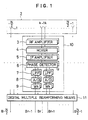
- Fig. 1 is a block diagram of a prior-art holographic radar shown in the paper "Digital Multiple Beamforming Techniques for Radar” by Abraham E. Ruvin and Leonard Weinberg in EASCON-78 Record , a publication of the Institute of Electrical and Electronics Engineers (IEEE). The radar shown in Fig.
- N antenna elements 1 forming an antenna array 2 RF amplifiers 3 connected to the antenna elements to amplify the radio-frequency signal received by the antenna element, mixers 4 which convert the received RF signal to an intermediate-frequency signal, IF amplifiers 5 which amplify the intermediate-frequency signal output from the mixers 5, phase detectors 6 which convert the output of the IF amplifiers to a baseband complex video signal while preserving the phase of the intermediate-frequency signal, low-pass filters 7 connected to the I (in-phase) channel output and Q (quadrature) channel output of the phase detectors 6, A/D converters 8 connected to the low-pass filters 7 for converting the analog baseband complex video signal to a digital signal, and multipliers 9 for weighting the digital signals output by the A/D converters 8 to adjust the sidelobe levels in the beamforming process.
- Receivers 10 comprise the preceding components 3 to 9.
- a digital multiple beamformer 11 performs mathematical operations on the outputs of the receivers 10 connected to the respective antenna elements 1 to create multiple beams corresponding in number to the
- This radar operates as described next.
- the radio-frequency signals received by the N antenna elements are amplified by the RF amplifiers 3, then down-converted by the mixers 4 to an intermediate frequency and amplified again by the IF amplifiers 5.
- the phase of the intermediate-frequency signals is detected by the phase detectors 6, which convert the signals to complex video signals comprising an I-channel component and a Q-channel component.
- the complex video signals are band-restricted by the low-pass filters 7, converted to digital complex video signals by the A/D converters 8, and weighted by the multipliers 9 to reduce the side lobes in the beamforming process, then supplied to the digital multiple beamformer 11.
- the direction in which the N antenna elements are aligned is shown as the x-axis in Fig. 2.
- ⁇ be the angle of the incoming RF wavefront with respect to the x-axis
- d be the antenna element spacing
- ⁇ be the wavelength.
- the phase difference between the signals received by adjacent antenna elements is then 2 ⁇ (dcos ⁇ ).
- the interval ⁇ r between the r-th beam and the r-1-th beam is given by equation (3):
- w is a constant determined by the coefficients Wk, and is generally set in the range from about 0.88 to 1.3.
- equation (1) describes a discrete Fourier transform (DFT).
- DFT discrete Fourier transform
- Holographic radars therefore employ the fast Fourier transform (FFT) algorithm to efficiently form a multiple beam in the field of observation, which is the coverage field determined by the antenna element beam width.
- FFT fast Fourier transform
- the field of observation of prior-art holographic radars is limited by the antenna element beam width (approximately 120°).
- the radar To scan the entire 360° field it is necessary for the radar to be rotated mechanically, which lengthens the time required for a 360° scan, or for the field to be divided among three or four radars, which increases the cost of the apparatus.
- Another problem is that a separate receiver is required for each antenna element, in contrast to a phased-array radar which performs analog beam forming in the RF stage.
- the large number of receivers adds significantly to the size and weight of the apparatus, and the receivers consume considerable power.
- WO-86/00760 provides a further multi beam antenna system having three sub-arrays and a high RF power switching capability.
- Electronic switch means enables different beam positions to be provided in an azimuthal hemispace in the range of only 0° to 180°.
- the present invention provides a holographic radar comprises a first antenna array comprising a plurality of antenna elements, a plurality of receivers and a digital multiple beam forming means for using the outputs of said receivers to generate multiple beams.
- the radar also comprises a further one or more antenna arrays each comprising a plurality of antenna elements, array switches for switching the connections between the plurality of receivers and the plurality of antenna arrays so that the plurality of receivers are connected to the antenna elements in one of the arrays at a time and switch controlling means for controlling the timing of switching of said array switches according to pulse hit numbers and range bin numbers.
- radar in accordance with this invention can enable a 360° scan to be accomplished rapidly and inexpensively.
- one receiver can be provided for every K antenna elements (where K is an integer equal to or greater than one), memory elements can be provided for storing the data output of the receivers and time division switches can be provided for switching the connections between the antenna elements and the array switches and between the receivers and the memory elements. These additional switches enable each receiver to process the RF signals received by the K antenna elements so the number of receivers can be reduced by a further factor of K, making the radar small in size and light in weight.
- the first antenna array and the further one or more antenna arrays are sub-arrays within a single array wherein the array switches and the receivers are provided for each antenna element in a single antenna sub-array.
- Figure 1 is a block diagram of a prior-art holographic radar.
- Figure 2 illustrates the principle of operation of the radar in Figure 1.
- Figure 3 is a block diagram of a holographic radar illustrating an embodiment of the present invention.
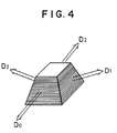
- Figure 4 is an oblique view of a quadruple antenna array.
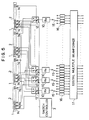
- Fig. 5 is a block diagram of a holographic radar illustrating another embodiment of the present invention.
- Fig. 3 shows a holographic radar comprising four antenna arrays 2, a set of receivers 10 equal in number to the antenna elements 1 in a single antenna array 2, switches 12 for switching the receivers 10 among the antenna arrays 2, and switch controlling means 13 for controlling the timing of the switches 12 according to a transmit pulse number and a range bin number.
- Components numbered 1 to 11 in Fig. 3 are identical to the corresponding components in Fig. 1.
- the four antenna arrays (D0, D1, D2, D3) are disposed as shown in Fig. 4, so that they divide the coverage range into four directions D0, D1, D2, and D3.
- Gt be the transmitting antenna gain
- Gr be the receiving antenna gain after multiple beamforming
- ⁇ be the transmit wavelength
- Pt be the peak transmitting power
- ⁇ be the radar cross-section of the target
- SNR be the signal-to-noise power ratio
- K Boltzmann's constant
- T represent absolute temperature
- B the receiver bandwidth
- NF the receiver noise figure
- L the system loss
- ⁇ R the range resolution
- k be the range bin number.
- the k-th pulse hit number Nk which is the coherent integral number required in the k-th range bin, is given by equation (4).
- the parameters inside the braces ⁇ in equation (4) are constants characteristic of the individual radar system, so the required pulse hit number Nk is proportional to the fourth power of the range bin number k.
- FIG. 5 Another embodiment of this invention is illustrated in Fig. 5.
- a set of switches 14 are located between the antenna elements 1 and the antenna array-switching switches 12, and another set of switches 15 are provided that connect the receivers 10 with a set of memory elements 16 which store the output from the receivers 10.
- the components numbered 1 to 13 are the same as in the embodiment shown in Fig. 3.
- Each group of K adjacent antenna elements is assigned to a single receiver 10.
- the L receivers 10 and the switches 14 and 15 connected to their input and output terminals all operate alike.
- the switches 14 are set to connect the input terminals of the switches 12 to the first antenna elements 1 in each group of K adjacent antenna elements 1 assigned one each receiver 10, and the switches 15 connect the output terminals of each receiver 10 to the first of its K assigned memory elements.
- the switches remain connected in this manner until the second transmit pulse is fired; during this interval the radio-frequency signals in all the range bins of the first antenna element in each group are amplified, detected, and A/D-converted, and the resulting digital complex video signals are stored in the first memory elements 16 in each group.
- the switches 14 and 15 switch to connect the second antenna element 1 in each group to the input terminal of the antenna array-switching switch 12, and connect the receiver output terminal to the second memory element 16, so that the radio-frequency signals received by the second antenna elements are amplified, detected, A/D-converted, and stored. This operation is repeated in sequence through the K-th transmit pulse.
- all the complex video signals are read out simultaneously, providing the digital multiple beamformer 11 with KL digital complex video signals, a number equal to the number N of antenna elements.
- the digital multiple beam former 11 then generates N multiple beams in the same way as in the prior art, just as if N antenna elements and N receivers had been used.
- This invention can be used to provide a compact, lightweight holographic radar with an improved 360° scan coverage rate. It can also be applied to other communication apparatus such as sonar apparatus and digital beamforming antennas that use a digital multiple beamformer.
Abstract
Description
- This invention relates to a holographic radar with improved 360° scanning performance and reduced size and weight.
- Fig. 1 is a block diagram of a prior-art holographic radar shown in the paper "Digital Multiple Beamforming Techniques for Radar" by Abraham E. Ruvin and Leonard Weinberg in EASCON-78 Record, a publication of the Institute of Electrical and Electronics Engineers (IEEE). The radar shown in Fig. 1 comprises
N antenna elements 1 forming anantenna array 2,RF amplifiers 3 connected to the antenna elements to amplify the radio-frequency signal received by the antenna element,mixers 4 which convert the received RF signal to an intermediate-frequency signal,IF amplifiers 5 which amplify the intermediate-frequency signal output from themixers 5, phase detectors 6 which convert the output of the IF amplifiers to a baseband complex video signal while preserving the phase of the intermediate-frequency signal, low-pass filters 7 connected to the I (in-phase) channel output and Q (quadrature) channel output of the phase detectors 6, A/D converters 8 connected to the low-pass filters 7 for converting the analog baseband complex video signal to a digital signal, and multipliers 9 for weighting the digital signals output by the A/D converters 8 to adjust the sidelobe levels in the beamforming process.Receivers 10 comprise the precedingcomponents 3 to 9. A digitalmultiple beamformer 11 performs mathematical operations on the outputs of thereceivers 10 connected to therespective antenna elements 1 to create multiple beams corresponding in number to the number of antenna elements. - This radar operates as described next.
- The radio-frequency signals received by the N antenna elements are amplified by the
RF amplifiers 3, then down-converted by themixers 4 to an intermediate frequency and amplified again by theIF amplifiers 5. The phase of the intermediate-frequency signals is detected by the phase detectors 6, which convert the signals to complex video signals comprising an I-channel component and a Q-channel component. The complex video signals are band-restricted by the low-pass filters 7, converted to digital complex video signals by the A/D converters 8, and weighted by themultipliers 9 to reduce the side lobes in the beamforming process, then supplied to the digitalmultiple beamformer 11. The direction in which the N antenna elements are aligned is shown as the x-axis in Fig. 2. Let α be the angle of the incoming RF wavefront with respect to the x-axis, let d be the antenna element spacing, and let λ be the wavelength. The phase difference between the signals received by adjacent antenna elements is then 2π(dcosα). The digitalmultiple beamformer 11 can simultaneously create N beams (r = -N/2, ..., 0, ..., N/2-1) having a maximum gain at

where Wk is a weighting coefficient introduced by the multipliers in thereceiver 10 to suppress side lobes. - The beam width δr of the r-th beam is given by equation (2) below:

The interval Δαr between the r-th beam and the r-1-th beam is given by equation (3):
In equation (2), w is a constant determined by the coefficients Wk, and is generally set in the range from about 0.88 to 1.3. In the digitalmultiple beamformer 11, equation (1) describes a discrete Fourier transform (DFT). Holographic radars therefore employ the fast Fourier transform (FFT) algorithm to efficiently form a multiple beam in the field of observation, which is the coverage field determined by the antenna element beam width. - Due to the configuration described above, the field of observation of prior-art holographic radars is limited by the antenna element beam width (approximately 120°). To scan the entire 360° field it is necessary for the radar to be rotated mechanically, which lengthens the time required for a 360° scan, or for the field to be divided among three or four radars, which increases the cost of the apparatus.
- Another problem is that a separate receiver is required for each antenna element, in contrast to a phased-array radar which performs analog beam forming in the RF stage. The large number of receivers adds significantly to the size and weight of the apparatus, and the receivers consume considerable power.
- WO-86/00760 provides a further multi beam antenna system having three sub-arrays and a high RF power switching capability. Electronic switch means enables different beam positions to be provided in an azimuthal hemispace in the range of only 0° to 180°.
- As is known from Figure 1, the present invention provides a holographic radar comprises a first antenna array comprising a plurality of antenna elements, a plurality of receivers and a digital multiple beam forming means for using the outputs of said receivers to generate multiple beams. In accordance with the invention, the radar also comprises a further one or more antenna arrays each comprising a plurality of antenna elements, array switches for switching the connections between the plurality of receivers and the plurality of antenna arrays so that the plurality of receivers are connected to the antenna elements in one of the arrays at a time and switch controlling means for controlling the timing of switching of said array switches according to pulse hit numbers and range bin numbers.
- By switching a single set of receivers among a number of antenna arrays, radar in accordance with this invention can enable a 360° scan to be accomplished rapidly and inexpensively.
- To further reduce the number of receivers in a single antenna array, one receiver can be provided for every K antenna elements (where K is an integer equal to or greater than one), memory elements can be provided for storing the data output of the receivers and time division switches can be provided for switching the connections between the antenna elements and the array switches and between the receivers and the memory elements. These additional switches enable each receiver to process the RF signals received by the K antenna elements so the number of receivers can be reduced by a further factor of K, making the radar small in size and light in weight.
- In a further embodiment the first antenna array and the further one or more antenna arrays are sub-arrays within a single array wherein the array switches and the receivers are provided for each antenna element in a single antenna sub-array.
- Figure 1 is a block diagram of a prior-art holographic radar.
- Figure 2 illustrates the principle of operation of the radar in Figure 1.
- Figure 3 is a block diagram of a holographic radar illustrating an embodiment of the present invention.
- Figure 4 is an oblique view of a quadruple antenna array. Fig. 5 is a block diagram of a holographic radar illustrating another embodiment of the present invention.
- An embodiment of this invention will be explained with reference to the drawings. Fig. 3 shows a holographic radar comprising four
antenna arrays 2, a set ofreceivers 10 equal in number to theantenna elements 1 in asingle antenna array 2,switches 12 for switching thereceivers 10 among theantenna arrays 2, and switch controllingmeans 13 for controlling the timing of theswitches 12 according to a transmit pulse number and a range bin number. Components numbered 1 to 11 in Fig. 3 are identical to the corresponding components in Fig. 1. - The operation of this holographic radar will be described next. The operation of the
receivers 10 and the digitalmultiple beamformer 11 will not be described because it is the same as in the prior art, but a detailed description will be given of theswitches 12 and the switch controllingmeans 13, which are the new components in this embodiment. - The four antenna arrays (D₀, D₁, D₂, D₃) are disposed as shown in Fig. 4, so that they divide the coverage range into four directions D₀, D₁, D₂, and D₃. Let Gt be the transmitting antenna gain, Gr be the receiving antenna gain after multiple beamforming, λ be the transmit wavelength, Pt be the peak transmitting power, σ be the radar cross-section of the target, SNR be the signal-to-noise power ratio, K be Boltzmann's constant, T represent absolute temperature, B be the receiver bandwidth, NF be the receiver noise figure, L be the system loss, ΔR be the range resolution, and k be the range bin number. Then the k-th pulse hit number Nk, which is the coherent integral number required in the k-th range bin, is given by equation (4).

The parameters inside the braces {} in equation (4) are constants characteristic of the individual radar system, so the required pulse hit number Nk is proportional to the fourth power of the range bin number k. - The switch controlling means 13 determines the required pulse hit number Nk in each range bin from equation (4) and the values of the parameters K, T, B, NF, L, SNR, ΔR, Pt, Gr, λ, and σ for the particular radar system. For each transmitted pulse, it divides the current transmit pulse number m by the required pulse hit number Nk for the range bin number k to obtain the quotient lk.

The brackets [] in equation (5) are the Gaussian notation for the greatest integer. The remainder Jk when the quotient lk is divided by the number of antenna arrays (4) is also found. Theswitches 12 are set to connect the receivers to theD₀ antenna array 2 if Jk = 0, to the D₁ array if Jk = 1, to the D₂ array if Jk = 2, and to the D₃ array if Jk = 3. This operation is carried out in all range bins k for every transmit pulse number m, thereby providing 360° scan coverage by a set of receivers for a single antenna array much faster than if the array had been turned mechanically as in the prior art. - Another embodiment of this invention is illustrated in Fig. 5. In this embodiment a set of
switches 14 are located between theantenna elements 1 and the antenna array-switching switches 12, and another set ofswitches 15 are provided that connect thereceivers 10 with a set ofmemory elements 16 which store the output from thereceivers 10. The components numbered 1 to 13 are the same as in the embodiment shown in Fig. 3. - The operation of a holographic radar according to the embodiment in Fig. 5 will be explained next. The internal operation of the
receivers 10 and the digitalmultiple beamformer 11 will not be described because it is the same as in the prior art, but detailed descriptions will be given of theswitches memory elements 16, which are the new elements in this embodiment. - The number of antenna elements N and the number of receivers L in this holographic radar are selected so that the ratio K = N/L is a natural number. Each group of K adjacent antenna elements is assigned to a
single receiver 10. TheL receivers 10 and theswitches - At the start of the observation, synchronized with the first transmitted pulse, the
switches 14 are set to connect the input terminals of theswitches 12 to thefirst antenna elements 1 in each group of Kadjacent antenna elements 1 assigned one eachreceiver 10, and theswitches 15 connect the output terminals of eachreceiver 10 to the first of its K assigned memory elements. The switches remain connected in this manner until the second transmit pulse is fired; during this interval the radio-frequency signals in all the range bins of the first antenna element in each group are amplified, detected, and A/D-converted, and the resulting digital complex video signals are stored in thefirst memory elements 16 in each group. Then in synchronization with the second transmit pulse, theswitches second antenna element 1 in each group to the input terminal of the antenna array-switchingswitch 12, and connect the receiver output terminal to thesecond memory element 16, so that the radio-frequency signals received by the second antenna elements are amplified, detected, A/D-converted, and stored. This operation is repeated in sequence through the K-th transmit pulse. When complex video signals have been stored in allK memory elements 16 assigned to each of theL receivers 10, all the complex video signals are read out simultaneously, providing the digitalmultiple beamformer 11 with KL digital complex video signals, a number equal to the number N of antenna elements. - The digital multiple beam former 11 then generates N multiple beams in the same way as in the prior art, just as if N antenna elements and N receivers had been used.
- This invention can be used to provide a compact, lightweight holographic radar with an improved 360° scan coverage rate. It can also be applied to other communication apparatus such as sonar apparatus and digital beamforming antennas that use a digital multiple beamformer.
Claims (3)
- A holographic radar comprising a first antenna array (2) comprising a plurality of antenna elements (1), a plurality of receivers (10) and a digital multiple beam forming means (11) for using the outputs of said receivers (10) to generate multiple beams; characterised in that the radar also comprises a further one or more antenna arrays (2), each comprising a plurality of antenna elements (1), array switches (12) for switching the connections between the plurality of receivers (10) and the plurality of antenna arrays (2) so that the plurality of receivers (10) is connected to the antenna elements (1) in one of the arrays (2) at a time and switch controlling means (13) for controlling the timing of switching of said array switches (12) according to pulse hit numbers and range bin numbers.
- A holographic radar according to claim 1, wherein said array switches (12) and said receivers (10) are provided, each per a group of plurality of antenna elements (1) in a single antenna array, with a plurality of said groups making up an antenna array (2) and said radar further comprises a plurality of memory elements (16) corresponding to the antenna elements (1) in one of the antenna arrays (2) for storing the output data from the receivers (10) and time division switches (14,15) disposed between said antenna elements (1) and said array switches (12) and between said receivers (10) and said memory elements (16), for time division input of the signals received in each group of antenna elements (1) through said array switches (12) to said receiver (10) and successive storage of the output of said receiver in the corresponding memory element.
- A holographic radar as claimed in claim 1, wherein the first antenna array and the further one or more antenna arrays (2) are part of a single array, and the array switches (12) and the receivers (10) are provided for each antenna element (1) in the antenna array connected by the array switches (12) to the receivers (10).
Applications Claiming Priority (4)
| Application Number | Priority Date | Filing Date | Title |
|---|---|---|---|
| JP62032101A JPS63198889A (en) | 1987-02-13 | 1987-02-13 | Holographic radar |
| JP62091189A JPH0668542B2 (en) | 1987-04-14 | 1987-04-14 | Holographic It Crader |
| JP91189/87 | 1987-04-14 | ||
| PCT/JP1988/000131 WO1988006295A1 (en) | 1987-02-13 | 1988-02-10 | Holographic radar |
Publications (3)
| Publication Number | Publication Date |
|---|---|
| EP0371133A1 EP0371133A1 (en) | 1990-06-06 |
| EP0371133A4 EP0371133A4 (en) | 1990-12-12 |
| EP0371133B1 true EP0371133B1 (en) | 1994-04-13 |
Family
ID=27287582
Family Applications (1)
| Application Number | Title | Priority Date | Filing Date |
|---|---|---|---|
| EP88907545A Expired - Lifetime EP0371133B1 (en) | 1987-02-13 | 1988-02-10 | Holographic radar |
Country Status (1)
| Country | Link |
|---|---|
| EP (1) | EP0371133B1 (en) |
Cited By (1)
| Publication number | Priority date | Publication date | Assignee | Title |
|---|---|---|---|---|
| US6721235B2 (en) * | 1997-02-03 | 2004-04-13 | Teratech Corporation | Steerable beamforming system |
Families Citing this family (5)
| Publication number | Priority date | Publication date | Assignee | Title |
|---|---|---|---|---|
| JP2939561B2 (en) * | 1989-09-08 | 1999-08-25 | 東洋通信機株式会社 | Microstrip antenna system |
| JP2576249B2 (en) * | 1990-01-30 | 1997-01-29 | 三菱電機株式会社 | Phased array radar beam management method and apparatus |
| US7548185B2 (en) | 2005-09-30 | 2009-06-16 | Battelle Memorial Institute | Interlaced linear array sampling technique for electromagnetic wave imaging |
| DE102011084610A1 (en) * | 2011-10-17 | 2013-04-18 | Robert Bosch Gmbh | Angle-resolving radar sensor |
| CN109638462B (en) * | 2018-12-21 | 2021-09-14 | 深圳市万普拉斯科技有限公司 | Antenna system, mobile terminal and switching method of antenna system |
Family Cites Families (1)
| Publication number | Priority date | Publication date | Assignee | Title |
|---|---|---|---|---|
| BR8407009A (en) * | 1983-08-11 | 1985-07-02 | Noel Carroll | PROCESS AND APPARATUS TO SEPARATE LIQUIDS |
-
1988
- 1988-02-10 EP EP88907545A patent/EP0371133B1/en not_active Expired - Lifetime
Cited By (1)
| Publication number | Priority date | Publication date | Assignee | Title |
|---|---|---|---|---|
| US6721235B2 (en) * | 1997-02-03 | 2004-04-13 | Teratech Corporation | Steerable beamforming system |
Also Published As
| Publication number | Publication date |
|---|---|
| EP0371133A1 (en) | 1990-06-06 |
| EP0371133A4 (en) | 1990-12-12 |
Similar Documents
| Publication | Publication Date | Title |
|---|---|---|
| US4924235A (en) | Holographic radar | |
| US5414433A (en) | Phased array radar antenna with two-stage time delay units | |
| US5592178A (en) | Wideband interference suppressor in a phased array radar | |
| US5179386A (en) | Cylindrical phased array antenna system to produce wide open coverage of a wide angular sector with high directive gain and strong capability to resolve multiple signals | |
| US20200371229A1 (en) | Hybrid multiple-input multiple-output (mimo) radar system | |
| US4451831A (en) | Circular array scanning network | |
| CN111370873B (en) | High-efficiency phase modulation system based on time modulation array | |
| US7205937B2 (en) | Non-multiple delay element values for phase shifting | |
| US11740208B2 (en) | Switched capacitor delay line | |
| CN112748428A (en) | Coherent MIMO radar processing method using DDMA waveform | |
| WO2001086755A2 (en) | Phased array antenna data re-alignment | |
| US5087917A (en) | Radar system | |
| EP0371133B1 (en) | Holographic radar | |
| US5479177A (en) | Phased array antenna system to produce wide-open coverage of a wide angular sector with high directive gain and wide frequency bandwidth | |
| US4894660A (en) | Range sidelobe reduction by aperiodic swept-frequency subpulses | |
| WO2007040635A1 (en) | Improved thinned array antenna system | |
| JPH0668542B2 (en) | Holographic It Crader | |
| US5410320A (en) | Cylindrical phased array antenna system to produce wide open coverage of a wide angular sector with high directive gain | |
| EP0232071A2 (en) | Sonar apparatus | |
| JP3197084B2 (en) | Radar equipment | |
| US5058081A (en) | Method of formation of channels for a sonar, in particular for a towed-array sonar | |
| US5252983A (en) | Method for reducing side lobes in antenna patterns | |
| US5243352A (en) | Method for processing antenna patterns | |
| US4757318A (en) | Phased array antenna feed | |
| JPH10209750A (en) | Dbf antenna system |
Legal Events
| Date | Code | Title | Description |
|---|---|---|---|
| PUAI | Public reference made under article 153(3) epc to a published international application that has entered the european phase |
Free format text: ORIGINAL CODE: 0009012 |
|
| 17P | Request for examination filed |
Effective date: 19881010 |
|
| AK | Designated contracting states |
Kind code of ref document: A1 Designated state(s): DE FR GB |
|
| A4 | Supplementary search report drawn up and despatched |
Effective date: 19901023 |
|
| AK | Designated contracting states |
Kind code of ref document: A4 Designated state(s): DE FR GB |
|
| 17Q | First examination report despatched |
Effective date: 19921202 |
|
| GRAA | (expected) grant |
Free format text: ORIGINAL CODE: 0009210 |
|
| AK | Designated contracting states |
Kind code of ref document: B1 Designated state(s): DE FR GB |
|
| REF | Corresponds to: |
Ref document number: 3889118 Country of ref document: DE Date of ref document: 19940519 |
|
| ET | Fr: translation filed | ||
| PLBE | No opposition filed within time limit |
Free format text: ORIGINAL CODE: 0009261 |
|
| STAA | Information on the status of an ep patent application or granted ep patent |
Free format text: STATUS: NO OPPOSITION FILED WITHIN TIME LIMIT |
|
| 26N | No opposition filed | ||
| PGFP | Annual fee paid to national office [announced via postgrant information from national office to epo] |
Ref country code: FR Payment date: 19960125 Year of fee payment: 9 |
|
| PGFP | Annual fee paid to national office [announced via postgrant information from national office to epo] |
Ref country code: GB Payment date: 19960201 Year of fee payment: 9 |
|
| PGFP | Annual fee paid to national office [announced via postgrant information from national office to epo] |
Ref country code: DE Payment date: 19960215 Year of fee payment: 9 |
|
| PG25 | Lapsed in a contracting state [announced via postgrant information from national office to epo] |
Ref country code: GB Effective date: 19970210 |
|
| GBPC | Gb: european patent ceased through non-payment of renewal fee |
Effective date: 19970210 |
|
| PG25 | Lapsed in a contracting state [announced via postgrant information from national office to epo] |
Ref country code: FR Effective date: 19971030 |
|
| PG25 | Lapsed in a contracting state [announced via postgrant information from national office to epo] |
Ref country code: DE Effective date: 19971101 |
|
| REG | Reference to a national code |
Ref country code: FR Ref legal event code: ST |