EP0371019B1 - Sheet-film cassette - Google Patents
Sheet-film cassette Download PDFInfo
- Publication number
- EP0371019B1 EP0371019B1 EP88903783A EP88903783A EP0371019B1 EP 0371019 B1 EP0371019 B1 EP 0371019B1 EP 88903783 A EP88903783 A EP 88903783A EP 88903783 A EP88903783 A EP 88903783A EP 0371019 B1 EP0371019 B1 EP 0371019B1
- Authority
- EP
- European Patent Office
- Prior art keywords
- locking
- cassette
- locking arm
- sheet
- grip piece
- Prior art date
- Legal status (The legal status is an assumption and is not a legal conclusion. Google has not performed a legal analysis and makes no representation as to the accuracy of the status listed.)
- Expired - Lifetime
Links
Images


Classifications
-
- G—PHYSICS
- G03—PHOTOGRAPHY; CINEMATOGRAPHY; ANALOGOUS TECHNIQUES USING WAVES OTHER THAN OPTICAL WAVES; ELECTROGRAPHY; HOLOGRAPHY
- G03B—APPARATUS OR ARRANGEMENTS FOR TAKING PHOTOGRAPHS OR FOR PROJECTING OR VIEWING THEM; APPARATUS OR ARRANGEMENTS EMPLOYING ANALOGOUS TECHNIQUES USING WAVES OTHER THAN OPTICAL WAVES; ACCESSORIES THEREFOR
- G03B17/00—Details of cameras or camera bodies; Accessories therefor
- G03B17/28—Locating light-sensitive material within camera
- G03B17/32—Locating plates or cut films
Abstract
Description
- The invention relates to a sheet-film cassette comprising a first and a second cassette portion connected by a hinge, in the first portion an exposure window and a light-shielding slider with a grip piece being arranged for shifting movement and in the second portion support means being provided for positioning a sheet film, two locking devices associated with the light-shielding slider and arranged in the grip piece thereof and adapted for engagement with one of the cassette portions, one of said locking devices comprising a locking arm mounted to the grip piece and being adapted for locking engagement with the second cassette portion and for being automatically reset when the cassette portions are pivoted to their open position.
- In a cassette of this type which has been disclosed in DE-PS 30 40 819, two locking devices are provided for the light-shielding slider, one preventing the light-shielding slider from being inadvertently operated and the other from being operated again after an exposure has been made. However, following exposure, the second locking device has to be manually moved to its operative position so that there exists the danger of the operator forgetting to actuate it and a double-exposure occurring.
- It is the object of the invention to design a sheet-film cassette of the generic type such that the danger of double exposure of a sheet film is excluded.
- In accordance with the invention this object is attained with the features of the characterising portion of
claim 1. - According to a useful modification of the invention, the locking arm is at one end positively mounted in the grip piece by means of mounting pins molded to it on either side. At its other end, the locking arm is provided with a locking nose adapted for engagement with the associated cassette portion.
- According to another useful modification of the invention, the control element is guided in a recess adjacent to the locking projection in the lower cassette portion which positions the sheet film.
- Advantageously, the locking arm is mounted in a recess of a bottom part of a grip piece consisting of two parts and is covered by the light-shielding slider which is secured between the two parts of said grip piece.
- According to still another useful modification of the invention, the control element is provided with a color mark which is visible from outside through an opening of the lower cassette portion and which indicates via the position of the control element the exposure condition of the sheet film.
- The design and arrangement of the second locking device as provided by the invention results in that the light-shielding slider cannot be moved again out of its covering position which it has assumed after an exposure so that the danger of double exposure is excluded.
- Further features and advantages can be inferred from the description of an embodiment of the invention illustrated in the drawings as well as from the sub-claims.
- The drawings show in
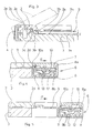
- Fig. 1
- a plan view of a sheet-film cassette;
- Fig. 2
- a rear view (hinge side) of the cassette according to Fig. 1;
- Fig. 3
- a sectional view along line C-C in Fig. 1;
- Fig. 4
- a sectional view along line B-B in Fig. 1 with the light-shielding slider in its closing position;
- Fig. 5
- the device according to Fig. 4 with the light-shielding slider partially extracted;
- Fig. 6
- a sectional view along line A-A in Fig. 1 with the light-shielding slider in its closed position;
- Fig. 7
- the device according to Fig. 6 with the light-shielding slider partially extracted;
- Fig. 8
- the device according to Fig. 6 with the double-exposure lock being operative;
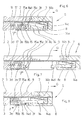
- Fig. 9
- a sectional view along line D-D in Fig. 1 with a sheet film loaded in the cassette;
- Fig. 10
- the device according to Fig. 9 without a sheet film.
- The sheet-
film cassette 1 comprises anupper portion 2 and alower portion 3 which are connected by aflexible hinge 4 secured by a snap fit (see Fig. 3). - The
upper portion 2 ofcassette 1 can be locked with thelower portion 3 of the cassette by an automatically or manually operated pivotable closing device 5 of a type known per se and not illustrated in detail. - An
exposure window 2a which can be closed by a light-shielding slider 9 guided in aguide 2b is arranged in theupper portion 2 ofcassette 1. - The
lower portion 3 ofcassette 1 features asupport surface 3a for asheet film 16 which is completely surrounded by aframe 3c. The twoshorter edge sections 3b ofsupport surface 3a are bent upwardly at an angle of about 6°. - Correspondingly designed
surface areas 2g of theupper portion 2 ofcassette 1 are arranged opposite and parallel to theseedge sections 3b. The longer sides ofexposure window 2a comprisesurface areas 2h running parallel with thesupport surface 3a. - A space "E" for accommodating a
sheet film 16 is provided between thesupport surface 3a with its two bent-offedge sections 3b oflower portion 3 and thesurface areas upper portion 2 extending parallel thereto and surrounding theexposure window 2a. - The bent-off
edge sections cassette 1 cause the two shorter edge sections of thesheet film 16 to be bent upwardly so that the sheet film is pretensioned in the direction towards thesupport surface 3a of thelower portion 3 and rests in a plane position on thesupport surface 3a. -
Frame 3c of thelower portion 3, which completely surrounds thefilm support surface endless groove 2c in theupper portion 2 ofcassette 1, both the frame and the groove being designed such that they form an interlocking light-tight labyrinth. - On the
lower portion 3 ofcassette 1,guide elements 2e are provided in the area of the hinge (see Fig. 3), said elements being received in arecess 2f of theupper portion 2 and serving to center the twocassette portions - The light-
shielding slider 9 has agrip piece 6 on which a first and a seconding locking device for said slider are arranged. - The grip piece, 6 consists of an
upper part 7 and alower part 8 screwed together with said upper part and the interposed light-shielding slider 9. - The first locking device according to Figs. 1, 4 and 5 comprises a
locking lever 10 which is arranged in arecess 8a of thelower part 8 ofgrip piece 6, and is held in engagement with arecess 2d in theupper portion 2 ofcassette 1 by means of aspring 11. -
Locking lever 10 is held by the light-shielding slider 9 covering therecess 8a and extends with alocking nose 10a through the light-shielding slider 9 into therecess 2d of theupper cassette portion 2. - Recess 8a moreover accommodates an
operating member 12 which can be operated from outside through an opening 8b in thelower part 8 ofgrip piece 6. The operatingmember 12 is influenced by aspring 13 supported on thelocking lever 10 and engages that end oflocking lever 10 which faces away from thelocking nose 10a. - The second locking device according to Figs. 1 and 6 to 8 comprises a
locking arm 14 which is positively held and pivotably mounted in anotherrecess 8c of thelower part 8 ofgrip piece 6 by mountingpins 14a arranged on either side of it. -
Locking arm 14 is provided in its mounting area with a support 14c and has aflexible spring arm 14b molded to it, with both the support and the spring arm resting against light-shielding slider 9 which covers therecess 8a. - At the free end of
locking arm 14, alocking nose 14d is arranged which engages aprojection 3f provided in arecess 3d in thelower cassette portion 3. Therecess 3d houses asliding shoe 15 which is spring-biased in the direction of the arrow "F" by aspring 17. The slidingshoe 15 is provided with astep 15a which cooperates with lockingnose 14d oflocking arm 14 in a manner to be described further below. At its lower side, thesliding shoe 15 is provided with acolor mark 15b visible from outside through an opening 3e in thelower cassette portion 3. - Sliding
shoe 15 is held in itsrecess 3d by a light-shielding means not illustrated which is arranged above said shoe and, in a manner known per se, provides a light-tight seal of the slot for the extracted light-shielding slider 9. - Further provisions of a known type and not illustrated are made in the area of the
grip piece 6 and the light-shielding slider 9 to prevent light from entering the interior of the cassette. - The
sheet film cassette 1 is handled as follows:
Aftercassette 1 has been loaded with asheet film 16 either automatically by means of a suitable unloading and reloading device or manually in a darkroom, the cassette is attached to a camera such as an X-ray camera. - At that stage, the
first locking device 10 to 13 assumes the locking position illustrated in Fig. 4 while thesecond locking device locking arm 14 with itslocking nose 14d is spring-biased to rest onstep 15a of slidingshoe 15. - In order to render the cassette ready for exposure, the
grip piece 6 is seized and the light-shielding slider 9 unlocked by means of theoperating member 12. The light-shielding slider 9 thus released (see Fig. 5) is extracted in the direction of the arrow "G" and thereby clears theexposure window 2a ofcassette 1. - While light-
shielding slider 9 is being extracted by means ofgrip piece 6, lockingnose 14d oflocking arm 14 slides offstep 15a of slidingshoe 15 and assumes the position illustrated in Fig. 7. - When the light-
shielding slider 9 has been extracted, thesheet film 16 is exposed. - Upon completion of the exposure, the light-shielding
slider 9 is shifted back intocassette 1 by means ofgrip piece 6, and theexposure window 2a is thus closed. - When the light-shielding
slider 9 is slid into the cassette in opposition to the direction of the arrow "G", lockingnose 14d of lockingarm 14 slides ontoprojection 3f ofrecess 3d. During that movement, the lockingnose 14d makes contact with theend face 15c of slidingshoe 15, urges said sliding shoe contrary to the direction of the arrow "F" and, under the action ofspring arm 14b, locks behindprojection 3f (see Fig. 8). - In the final position of light-shielding
slider 9 and itsgrip piece 6 respectively, in which said slider is shifted into the cassette, lockinglever 10, too, is once again received inrecess 2d of the upper cassette portion 2 (see Fig. 4). - Should an attempt be made to open the light-shielding
slider 9 again after an exposure has been made, thefirst locking device 10, 12 (Fig. 4) could be actuated. However, lockingarm slider 9 from being erroneously extracted. - The
second locking device - When the
second locking device color mark 15b of slidingshoe 15, which is visible from outside through anopening 3e in thelower cassette portion 3. - At the end of the exposure and with light-shielding
slider 9 in its covering position,cassette 1 is removed from the camera. - The exposed
sheet film 16 is removed fromcassette 1 either automatically in daylight in an unloading and reloading device or manually in a darkroom. - When the
cassette 1 is opened for this purpose by operation of the closing device 5 and theupper cassette portion 2 is pivoted to its open position,grip piece 6, which engages theupper cassette portion 2 via the light-shieldingslider 9, also moves away from the lower cassette portion 3 (shown in dash-dotted lines in Fig. 3). - At the same time, locking
nose 14d of lockingarm 14 leavesprojection 3f and slidingshoe 15 so that slidingshoe 15 is able to slide, under the action ofspring 17, in the direction of the arrow "F" until itsstep 15a is positioned beneath the lockingnose 14d of lockingarm 14. - The
second locking device 14, 15 (double-exposure lock) has thus also been unlocked and, upon loading of another sheet film and closing of thecassette portions -
Cassette 1 is now ready for exposure, which can also be ascertained from outside by the absence of the double-exposure lock signal (color mark 15b). - In order that it can be ascertained in the closed position of the sheet-
film cassette 1 whether or not a sheet film has been loaded,cassette 1 is provided with a load-condition indicator. - The load-condition indicator comprises an
indicator element 18 which is movable perpendicularly to the sheet-film support surface 3a. Theindicator element 18 is guided in asleeve 19 mounted in anopening 3g of thelower cassette portion 3 and under the action of its own weight slides in abore 19a ofsleeve 19, which opens towards the exterior. The inner wall ofbore 19a is provided with acolor mark 19b which is either visible from the exterior of the cassette or covered, depending on the position of theindicator element 18. - For light-sealing purposes the
indicator element 18 and thesleeve 19 interlock in a labyrinth-type manner and are designed such that theindicator element 18 is movable to and fro over a distance "H". - The
indicator element 18 is arranged on thelower cassette portion 3 which positions thesheet film 16 and opposite to the opening of theexposure window 2a. It is guided for movement over a distance "H" from a position, in which it is flush with the outer surface of thelower cassette portion 3, to a position, in which it extends by a limited amount into the opening ofexposure window 2a. - The
cassette 1 is loaded with asheet film 16 when it is in the position in which the lower cassette portion is at the bottom as shown in Fig. 3. In this position, theindicator element 18 is flush with the outer surface of thelower cassette portion 3 and does not extend beyond thesupport surface 3a ofsheet film 16. - In order to ascertain whether or not a
sheet film 16 is loaded in aclosed cassette 1, thecassette 1 is turned around so that thelower cassette portion 3 is positioned at the top as illustrated in Fig. 9. With asheet film 16 loaded, theindicator element 18 rests againstsheet film 16 as shown in Fig. 9 and thus cannot move. This "cassette loaded" condition is indicated by the flush alignment of theindicator element 18 with the outer cassette surface and by the fact thatcolor mark 19b is not visible. - If the loading condition is checked and there is no sheet film loaded in
cassette 1,indicator element 18 drops by its own weight by the distance "H" downwardly to the position illustrated in Fig. 10 in which is extends into the opening ofexposure window 2a. This clearscolor mark 19b so that it can be seen from outside that no sheet film is present incassette 1. - When the
indicator element 18 drops inwardly by the distance "H", bore 19a is partially cleared and thus a recess produced on the outer cassette surface which can be sensed. This offers the opportunity of ascertaining the loading condition even in a darkroom without thecassette 1 having to be opened. - The indicator means 3a and 15b of the double-
exposure lock condition indicator lower cassette portion 3 and are, moreover, associated with the same cassette end (see Fig. 1). This facilitates handling of thecassette 1, because the loading condition - cassette empty or loaded - and the exposure condition - sheet film exposed or unexposed - can be ascertained at the same side of the cassette. - Moreover, the operating
member 12 for thefirst locking device
Claims (7)
- A sheet film cassette (1) comprising a first and a second cassette portion (2, 3) connected by a hinge (4), in the first portion (2) an exposure window (2a) and a light-shielding slider (9) with a grip piece (6) being arranged for shifting movement and in the second portion (3) support means (3a, 3b) being provided for positioning a sheet film (16), two locking devices (10, 14) associated with the light-shielding slider and arranged in the grip piece thereof and adapted for engagement with one of the cassette portions, one of said locking devices (14) comprising a locking arm (14) mounted to the grip piece (6) and being adapted for locking engagement with the second cassette portion (3) and for being automatically reset when the cassette portions (2, 3) are pivoted to their open position, characterized in that the locking arm (14) is rigidly connected with said grip piece in the direction of its movement and spring-biased into engagement with a projection (3f) of the second cassette portion (3), and in that the second cassette portion (3) comprises a control element (15) which is movable in the direction of the shifting movement of the slider (9), spring-biased into a locking path of the locking arm (14) to prevent locking in its reset position, and movable away from the locking path of the locking arm (14) to enable locking in its locking position.
- A sheet-film cassette according to claim 1, characterized in that the locking arm (14) is positively held and pivotably mounted at one end in the grip piece (6) by means of mounting pins (14a) molded to it on either side and in that the locking arm (14) comprises at its other end a locking nose (14d) adapted for engagement with the associated cassette portion (3).
- A sheet-film cassette according to claim 1 or 2, characterized in that the control element (15) is guided in a recess (3d) adjacent to the projection (3f) in the second cassette portion (3), and in that the locking arm (14) is mounted in a recess (8c) of a lower part (8) of the grip piece (6) which consists of two parts (7, 8).
- A sheet-film cassette according to claim 3, characterized in that the light-shielding slider (9) is secured between an upper part (7) and the lower part (8) of the grip piece (6) and covers the recess (8c) and the locking arm (14) located therein.
- A sheet-film cassette according to any of claims 1 to 4, characterized in that a spring arm (14b) is molded to the locking arm (14) for biasing the locking arm into engagement with the projection (3f).
- A sheet-film cassette according to any of claims 1 to 5, characterized in that the control element (15) comprises an end face (15c) arranged within the path of shifting movement of the locking arm (14) and continuing in a step (15a).
- A sheet-film cassette according to any of claims 1 to 6, characterized in that a color mark (15b) is arranged on a lower side of the control element (15), said color mark being visible through an opening (3e) on the outer side of the cassette, when the control element is in its locking position.
Priority Applications (1)
| Application Number | Priority Date | Filing Date | Title |
|---|---|---|---|
| AT88903783T ATE97243T1 (en) | 1987-04-09 | 1988-04-08 | SHEET FILM CASSETTE. |
Applications Claiming Priority (2)
| Application Number | Priority Date | Filing Date | Title |
|---|---|---|---|
| DE19873711943 DE3711943A1 (en) | 1987-04-09 | 1987-04-09 | PLAN FILM CASSETTE |
| DE3711943 | 1987-04-09 |
Publications (2)
| Publication Number | Publication Date |
|---|---|
| EP0371019A1 EP0371019A1 (en) | 1990-06-06 |
| EP0371019B1 true EP0371019B1 (en) | 1993-11-10 |
Family
ID=6325193
Family Applications (1)
| Application Number | Title | Priority Date | Filing Date |
|---|---|---|---|
| EP88903783A Expired - Lifetime EP0371019B1 (en) | 1987-04-09 | 1988-04-08 | Sheet-film cassette |
Country Status (4)
| Country | Link |
|---|---|
| EP (1) | EP0371019B1 (en) |
| JP (1) | JP2688433B2 (en) |
| DE (2) | DE3711943A1 (en) |
| WO (1) | WO1988008151A1 (en) |
Families Citing this family (3)
| Publication number | Priority date | Publication date | Assignee | Title |
|---|---|---|---|---|
| DE9101332U1 (en) * | 1991-02-06 | 1991-04-25 | Agfa-Gevaert Ag, 5090 Leverkusen, De | |
| CN109407442A (en) * | 2018-11-30 | 2019-03-01 | 江苏科技大学 | A kind of camera double exposure radical occlusion device |
| CN112489837B (en) * | 2020-11-27 | 2024-04-02 | 中广核检测技术有限公司 | Sheet distributing device and method for in-service inspection of claw gaskets of control rod driving mechanism |
Family Cites Families (2)
| Publication number | Priority date | Publication date | Assignee | Title |
|---|---|---|---|---|
| DE3040819C2 (en) * | 1980-10-30 | 1983-10-20 | Agfa-Gevaert Ag, 5090 Leverkusen | Sheet film cassette |
| DE3119977C2 (en) * | 1981-05-20 | 1986-11-27 | Agfa-Gevaert Ag, 5090 Leverkusen | Flat film cassette for holding two films |
-
1987
- 1987-04-09 DE DE19873711943 patent/DE3711943A1/en active Granted
-
1988
- 1988-04-08 JP JP63503486A patent/JP2688433B2/en not_active Expired - Fee Related
- 1988-04-08 EP EP88903783A patent/EP0371019B1/en not_active Expired - Lifetime
- 1988-04-08 DE DE3885615T patent/DE3885615T2/en not_active Expired - Fee Related
- 1988-04-08 WO PCT/EP1988/000293 patent/WO1988008151A1/en active IP Right Grant
Also Published As
| Publication number | Publication date |
|---|---|
| DE3885615T2 (en) | 1994-05-19 |
| DE3711943A1 (en) | 1988-10-20 |
| DE3711943C2 (en) | 1990-12-20 |
| DE3885615D1 (en) | 1993-12-16 |
| EP0371019A1 (en) | 1990-06-06 |
| JPH02502946A (en) | 1990-09-13 |
| JP2688433B2 (en) | 1997-12-10 |
| WO1988008151A1 (en) | 1988-10-20 |
Similar Documents
| Publication | Publication Date | Title |
|---|---|---|
| US4522478A (en) | Cover-equipped camera | |
| US4240735A (en) | Protective cover for taking lens of camera | |
| JPH05781B2 (en) | ||
| EP0371019B1 (en) | Sheet-film cassette | |
| US4554603A (en) | Adapter for a miniature type tape cassette | |
| US4493545A (en) | Film cassette | |
| US4249819A (en) | Arrangement for feeding sheets into a developing machine | |
| US5729784A (en) | Photographic camera | |
| US4367028A (en) | Camera with protective cover | |
| JPH0887064A (en) | Cartridge chamber door locking device of camera | |
| EP0251171B1 (en) | Camera door release and film rewind interlock apparatus | |
| US3427943A (en) | Cinematographic or photographic filming apparatus | |
| GB2134076A (en) | Tape cassette having a transparent window | |
| US3665830A (en) | Film transport mechanism | |
| US4710006A (en) | Shutter release and film advance interlock mechanism | |
| JPH08234283A (en) | Camera with interlock mechanism for prevention of tilt of film loading chamber | |
| US4273434A (en) | Photographic camera | |
| US4572641A (en) | Latch device for cartridge compartment door of a camera | |
| EP0366657B1 (en) | Sheet-film cassette | |
| US4571043A (en) | Dustproofing device for thin vertically disposed camera | |
| US6450709B1 (en) | Interchangeable film back type camera | |
| US3936846A (en) | Battery magazine in single lens reflex camera | |
| US4596452A (en) | Thin disc camera | |
| US4527873A (en) | Camera loading door interlock | |
| US6055380A (en) | Cameras |
Legal Events
| Date | Code | Title | Description |
|---|---|---|---|
| PUAI | Public reference made under article 153(3) epc to a published international application that has entered the european phase |
Free format text: ORIGINAL CODE: 0009012 |
|
| 17P | Request for examination filed |
Effective date: 19891006 |
|
| AK | Designated contracting states |
Kind code of ref document: A1 Designated state(s): AT CH DE FR GB LI |
|
| RAP1 | Party data changed (applicant data changed or rights of an application transferred) |
Owner name: EASTMAN KODAK COMPANY Owner name: KODAK AKTIENGESELLSCHAFT |
|
| 17Q | First examination report despatched |
Effective date: 19920716 |
|
| RAP1 | Party data changed (applicant data changed or rights of an application transferred) |
Owner name: EASTMAN KODAK COMPANY Owner name: KODAK AKTIENGESELLSCHAFT |
|
| GRAA | (expected) grant |
Free format text: ORIGINAL CODE: 0009210 |
|
| AK | Designated contracting states |
Kind code of ref document: B1 Designated state(s): AT CH DE FR GB LI |
|
| REF | Corresponds to: |
Ref document number: 97243 Country of ref document: AT Date of ref document: 19931115 Kind code of ref document: T |
|
| REF | Corresponds to: |
Ref document number: 3885615 Country of ref document: DE Date of ref document: 19931216 |
|
| ET | Fr: translation filed | ||
| PLBE | No opposition filed within time limit |
Free format text: ORIGINAL CODE: 0009261 |
|
| STAA | Information on the status of an ep patent application or granted ep patent |
Free format text: STATUS: NO OPPOSITION FILED WITHIN TIME LIMIT |
|
| 26N | No opposition filed | ||
| PGFP | Annual fee paid to national office [announced via postgrant information from national office to epo] |
Ref country code: AT Payment date: 20010314 Year of fee payment: 14 |
|
| PGFP | Annual fee paid to national office [announced via postgrant information from national office to epo] |
Ref country code: CH Payment date: 20010627 Year of fee payment: 14 |
|
| REG | Reference to a national code |
Ref country code: GB Ref legal event code: IF02 |
|
| PG25 | Lapsed in a contracting state [announced via postgrant information from national office to epo] |
Ref country code: AT Free format text: LAPSE BECAUSE OF NON-PAYMENT OF DUE FEES Effective date: 20020408 |
|
| PG25 | Lapsed in a contracting state [announced via postgrant information from national office to epo] |
Ref country code: LI Free format text: LAPSE BECAUSE OF NON-PAYMENT OF DUE FEES Effective date: 20020430 Ref country code: CH Free format text: LAPSE BECAUSE OF NON-PAYMENT OF DUE FEES Effective date: 20020430 |
|
| REG | Reference to a national code |
Ref country code: CH Ref legal event code: PL |
|
| PGFP | Annual fee paid to national office [announced via postgrant information from national office to epo] |
Ref country code: GB Payment date: 20050314 Year of fee payment: 18 |
|
| PGFP | Annual fee paid to national office [announced via postgrant information from national office to epo] |
Ref country code: FR Payment date: 20050401 Year of fee payment: 18 |
|
| PGFP | Annual fee paid to national office [announced via postgrant information from national office to epo] |
Ref country code: DE Payment date: 20050429 Year of fee payment: 18 |
|
| PG25 | Lapsed in a contracting state [announced via postgrant information from national office to epo] |
Ref country code: GB Free format text: LAPSE BECAUSE OF NON-PAYMENT OF DUE FEES Effective date: 20060408 |
|
| PG25 | Lapsed in a contracting state [announced via postgrant information from national office to epo] |
Ref country code: DE Free format text: LAPSE BECAUSE OF NON-PAYMENT OF DUE FEES Effective date: 20061101 |
|
| GBPC | Gb: european patent ceased through non-payment of renewal fee |
Effective date: 20060408 |
|
| REG | Reference to a national code |
Ref country code: FR Ref legal event code: ST Effective date: 20061230 |
|
| PG25 | Lapsed in a contracting state [announced via postgrant information from national office to epo] |
Ref country code: FR Free format text: LAPSE BECAUSE OF NON-PAYMENT OF DUE FEES Effective date: 20060502 |