EP0370724A2 - Luftreifen - Google Patents
Luftreifen Download PDFInfo
- Publication number
- EP0370724A2 EP0370724A2 EP89311992A EP89311992A EP0370724A2 EP 0370724 A2 EP0370724 A2 EP 0370724A2 EP 89311992 A EP89311992 A EP 89311992A EP 89311992 A EP89311992 A EP 89311992A EP 0370724 A2 EP0370724 A2 EP 0370724A2
- Authority
- EP
- European Patent Office
- Prior art keywords
- rubber
- tire
- tread
- base
- base rubber
- Prior art date
- Legal status (The legal status is an assumption and is not a legal conclusion. Google has not performed a legal analysis and makes no representation as to the accuracy of the status listed.)
- Granted
Links
Images


Classifications
-
- B—PERFORMING OPERATIONS; TRANSPORTING
- B60—VEHICLES IN GENERAL
- B60C—VEHICLE TYRES; TYRE INFLATION; TYRE CHANGING; CONNECTING VALVES TO INFLATABLE ELASTIC BODIES IN GENERAL; DEVICES OR ARRANGEMENTS RELATED TO TYRES
- B60C9/00—Reinforcements or ply arrangement of pneumatic tyres
- B60C9/18—Structure or arrangement of belts or breakers, crown-reinforcing or cushioning layers
-
- B—PERFORMING OPERATIONS; TRANSPORTING
- B60—VEHICLES IN GENERAL
- B60C—VEHICLE TYRES; TYRE INFLATION; TYRE CHANGING; CONNECTING VALVES TO INFLATABLE ELASTIC BODIES IN GENERAL; DEVICES OR ARRANGEMENTS RELATED TO TYRES
- B60C11/00—Tyre tread bands; Tread patterns; Anti-skid inserts
- B60C11/0041—Tyre tread bands; Tread patterns; Anti-skid inserts comprising different tread rubber layers
- B60C11/005—Tyre tread bands; Tread patterns; Anti-skid inserts comprising different tread rubber layers with cap and base layers
-
- B—PERFORMING OPERATIONS; TRANSPORTING
- B60—VEHICLES IN GENERAL
- B60C—VEHICLE TYRES; TYRE INFLATION; TYRE CHANGING; CONNECTING VALVES TO INFLATABLE ELASTIC BODIES IN GENERAL; DEVICES OR ARRANGEMENTS RELATED TO TYRES
- B60C11/00—Tyre tread bands; Tread patterns; Anti-skid inserts
- B60C11/14—Anti-skid inserts, e.g. vulcanised into the tread band
- B60C2011/147—Foamed rubber or sponge rubber on the tread band
Definitions
- the present invention relates to pneumatic tires having an improved tread structure.
- pneumatic tires as described in Japanese patent application Laid-open No. 63-93,604 are formerly known, in which their tread structure is improved.
- Such tires are pneumatic tires having a cap/base structure in which a tread is constituted by an outer tread portion which is arranged on a radially outer side of the tire and made of a single kind of a rubber and an inner tread portion which is arranged radially inside a surface of a wearing indicator of the tread and also on a radially inner side of the tire and made of plural kinds of rubbers.
- the inner tread portion is divided into at least three zones in an axial direction of the tire, that is, a central zone spread over tire equator, side zones continuously positioned on the opposite sides of the central zone.
- Hardness of the tread rubber in the central zone of the inner tread portion is made smaller than that of the tread rubber in the side zones and that of the tread rubber in the outer tread portion, and hardness of the tread rubber in the inner tread portion is increased as it goes from the central zone to the side zones. Further, hardness of the tread rubber of that portion of the inner tread which is located on the axially outermost portion of the tire is not greater than that of the tread rubber in the outer tread portion.
- the tread rubber that is, the rubber of the inner and outer tread portions is all made of a non-foam rubber in the above-mentioned tire.
- a non-foam rubber When compression forces are applied to such a non-foam rubber, its volume is not almost reduced.
- a compression modulus of the entire tread does not almost decrease in actual.
- anti-vibration riding comfortability can merely be improved to some extent, but no sufficient effect cannot be obtained during actual use.
- a tensile modulus of an ordinary non-foam rubber is reduced corresponding to reduction in the rubber hardness as mentioned above.
- the pneumatic tire comprising a toroidal carcass, a belt arranged radially outside the carcass and consisting of at least two rubberized cord layers, a tread rubber surrounding the belt, wherein the tread rubber is constituted by a base rubber made of a foamed rubber and a cap rubber made of a non-foam rubber and arranged radially outside the base rubber.
- the widthwise center of the base rubber is almost in conformity with the equatorial plane of the tire and that the width of the base rubber is narrower than that of the belt so that the cap rubber may be laid on widthwise opposite sides of the base rubber.
- the expansion ratio (Vs) of the base rubber is preferivelyably in a range from 10% to 50%.
- the ratio b/W in which b and W are the width of the base rubber and the width of the ground contact area of the tread, respectively, preferably falls in a range from 0.15 to 0.65.
- the ratio t/T in which t and T are the maximum gauge of the base rubber and that of the tread rubber, respectively falls in a range from 0.05 to 0.50.
- the tread rubber of the pneumatic tire according to the present invention involves the base rubber made of the foamed rubber.
- compression forces When compression forces are applied to such a foamed rubber, bubbles inside the rubber are collapsed to decrease the volume by compression. Consequently, its compression modulus becomes smaller as compared with that of the non-foam rubber.
- the rigidity of the above tread rubber against the compression forces becomes lower.
- the cap rubber when the cap rubber is arranged not only radially outside the base rubber but also on the widthwise opposite sides thereof, rigidity of the opposite shoulder portions of the pneumatic tire and bending rigidity of the tread rubber are maintained at respective levels as conventionally possessed, while cornering stability is prevented from lowering. At the same time, the foamed rubber having a higher wearing rate, that is, the base rubber is protected against wearing. Further, when the expansion ratio (Vs), the ratio b/W and the gauge ratio t/T fall within the above-specified respective ranges, anti-vibration riding comfortability and cornering stability can both be improved as compared with conventional tires, and drop in entire wearing life can be prevented.
- Vs expansion ratio
- the ratio b/W and the gauge ratio t/T fall within the above-specified respective ranges, anti-vibration riding comfortability and cornering stability can both be improved as compared with conventional tires, and drop in entire wearing life can be prevented.
- a reference numeral 1 is a pneumatic tire.
- the tire comprises a toroidal carcass 3 having axially opposite end portions turned up around beads 2, a belt 4 radially outwardly arranged on the carcass 3, and a tread rubber 5 surrounding the belt 4.
- the belt 4 is constituted by piling at least two rubberized cord layers 6 one upon another.
- the tread rubber 5 is constituted by a base rubber 8 arranged on a radially inner side of the tire and made of a foamed rubber containing numerous closed cells, and a cap rubber 9 arranged on a radially outer side of the tire and made of a non-foam rubber.
- the base rubber 8 When compression forces act upon the foamed rubber constituting the base rubber 8, the closed cells inside the foamed rubber are collapsed to reduce their volume. Accordingly, compression modulus of the foamed rubber is smaller than that of the non-foam rubber constituting the cap rubber 9. Further, the base rubber 8 is so arranged that its widthwise center may be almost in conformity with the equatorial plane 10 of the tire. The width b of the base rubber is smaller than that of the belt 4. By so constructing, the cap rubber 9 made of the above non-foam rubber is arranged radially outside and on widthwise opposite sides of the base rubber 8.
- the outer and opposite sides of the base rubber 8 are surrounded with the cap rubber, so that cornering stability can be prevented from lowering, while rigidity of opposite shoulder portions 11 of the tire 1 and bending rigidity of the tread rubber 5 are maintained at same levels as those of the tire in which the tread rubber is entirely made of the unfoamable rubber.
- the foamed rubber having a higher wearing rate, that is, the base rubber 8 is protected against wearing.
- the ratio b/W falls in a range from 0.15 to 0.65, in which b and W are the width of the base rubber 8 and the ground contact width of the tread when a normal internal pressure is applied to the tire 1 fitted to a normal rim under application of a normal load, respectively.
- the ratio b/W is less than 0.15, anti-vibration riding comfortability is lowered than the conventional tires as mentioned later.
- the ratio is more than 0.65, the cornering stability is lowered as compared with the conventional tires.
- the expansion ratio (Vs) of the base rubber 8 falls in the range from 10 to 50%. The reason is that if the expansion ratio is less than 10%, the anti-vibration riding comfortability is lowered than the conventional tires as mentioned later. On the other hand, if the expansion ratio is more than 50%, the cornering stability is lowered than that of the conventional tires, and the complete wear life is rapidly lowered.
- Vs the expansion ratio (Vs) is represented by the following equation.
- Vs ⁇ ( ⁇ 0 - ⁇ g )/( ⁇ 1 - ⁇ g ) - 1 ⁇ ⁇ 100(%) (1), wherein: ⁇ 1 is the density (g/cm3) of the foamed rubber; ⁇ 0 is the density (9/cm3) of a solid part of the foamed rubber; and ⁇ g is the density (g/cm3) of a gas contained in the foams of the foamed rubber.
- the gauge ratio t/T falls in the range from 0.05 to 0.50, in which t and T are the maximum gauge of the base rubber 8 and that of the tread rubber 5, respectively.
- t and T are the maximum gauge of the base rubber 8 and that of the tread rubber 5, respectively.
- the gauge ratio t/T is less than 0.05, the anti-vibration riding comfortability is lowered than the conventional tires as mentioned later.
- the gauge ratio is more than 0.50, the base rubber 8, which has a greater wearing rate, comes out from the surface of the tire at the wear final stage to rapidly lower the complete wear life, and to lower the cornering stability than the conventional tires.
- a deep main groove 17 is formed in the surface portion 16 of the tread of the tire 1, the base rubber 8 may appear at the groove bottom of the main groove 17.
- the base rubber 8 made of the foamed rubber is weaker than the non-foam rubber, and is easily broken.
- the base rubber must not come out from the groove bottom of the main groove 17.
- those portions of the base rubber which overlap with the main grooves 17 are dented toward the radially inner side of the tire.
- Comparative Tire 1 in which a tread rubber was entirely made of a non-foam rubber, and Test Tires 1 through 7 to which the present invention was applied were prepared.
- Various dimensions of each of the tires are shown in Table 1, and their tire size was 185/70SR14.
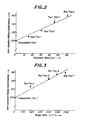
- each of the tires was fitted to a vehicle, its anti-vibration riding comfortability was evaluated by driver's feeling. Results are shown in Table 1 by index.
- Table 1 the anti-vibration riding comfortability was improved for the Test Tires.
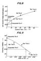
- Figs. 2 and 3 as the expansion ratio (Vs) increases or as the gauge ratio t/T increases, the anti-vibration riding comfortability is improved. Further, the complete wear life was measured by running each of the tires in this test.
- the complete wear life means a running distance at which at least one portion of the remaining main groove became 1.0 mm or less in depth.
- the main groove means the deepest groove in the tread, and is generally a wide groove extending continuously in a circumferential direction. Results are shown in Figs. 4 and 5. From the results, it is seen that as the expansion ratio (Vs) increases or as the gauge ratio t/T increases, the complete wear life lowers. If the expansion ratio (Vs) exceeds 50% or if the gauge ratio t/T exceeds 0.5, the complete wear life rapidly drops. Thus, it is preferable that the expansion ratio (Vs) is not more than 50% and that the gauge ratio t/T is not more than 0.50.
- Comparative Tires 2 and 3 in which a tread rubber was entirely made of a non-foam rubber and Test tires 8 through 14 to which the present invention was applied were prepared.
- Comparative Tire 2 is a tire in which contradictory properties, that is, the anti-vibration riding comfortability and the cornering stability were both satisfied by selecting an appropriate kind of a non-foam rubber.
- Comparative tire 2 had a practically sufficient anti-vibration riding comfortability and cornering stability.
- the tire size of each of the tires used in this Test Example was 185/70SR14, and the ground contact width of the tread was 121 mm.
- Various dimensions of the tires are shown in Table 2.
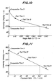
- the ratio b/W is not less than 0.15, that the gauge ratio t/T is not less than 0.55, and that the expansion ratio (Vs) is not less than 10%.
- the ratio b/W increases, or as the gauge t/T increases, or as the expansion ratio (Vs) increases, the cornering stability drops. If the ratio b/W exceeds 0.65, or if the gauge ratio t/T exceeds 0.50, or if the expansion ratio (Vs) exceeds 50%, the cornering stability becomes poorer than the above Comparative Tire 2.
- the ratio b/W is not more than 0.65, that the gauge ratio t/T is not more than 0.50, and that the expansion ratio (Vs) is not more than 50%.
- the 10% compression modulus means a value obtained by measuring compression stresses occurring when static compression forces were applied to a flat rubber plate having lengthwise and breadthwise lengths being both 40 mm and a thickness of 10 mm from upper and lower sides, and dividing a compression stress by a compression strain, the compression stress being a value when the thickness of the flat rubber plate is reduced by 10%.
- Fig. 12 is a sectional view of a second embodiment of the present invention.
- the widthwise center of a base rubber 21 is spaced from the equatorial plane 10 of the tire such that the base rubber 21 is entirely arranged on one side of the equatorial plane 10.
- Fig. 13 is a sectional view of a third embodiment of the present invention.
- narrow base rubbers 22 and 23 are provided on opposite sides of the tire equatorial plane 10, respectively, and a cap rubber 9 is arranged above and between the base rubbers 22 and 23.
- the total value of widths c and d of the base rubbers 22 and 23, respectively, is equal to the width b of the base rubber 8 in the first embodiment.
- the radially outer side surface of the base rubber is flat.
- the radially outer surface of the base rubber may be corrugated.
- the anti-vibration riding comfortability can be improved to a large extent without deteriorating the wear resistance.
Landscapes
- Engineering & Computer Science (AREA)
- Mechanical Engineering (AREA)
- Tires In General (AREA)
Applications Claiming Priority (4)
| Application Number | Priority Date | Filing Date | Title |
|---|---|---|---|
| JP29547388 | 1988-11-22 | ||
| JP295473/88 | 1988-11-22 | ||
| JP1112994A JPH02225106A (ja) | 1988-11-22 | 1989-05-02 | 空気入りタイヤ |
| JP112994/89 | 1989-05-02 |
Publications (3)
| Publication Number | Publication Date |
|---|---|
| EP0370724A2 true EP0370724A2 (de) | 1990-05-30 |
| EP0370724A3 EP0370724A3 (de) | 1991-03-27 |
| EP0370724B1 EP0370724B1 (de) | 1994-08-10 |
Family
ID=26452023
Family Applications (1)
| Application Number | Title | Priority Date | Filing Date |
|---|---|---|---|
| EP89311992A Expired - Lifetime EP0370724B1 (de) | 1988-11-22 | 1989-11-20 | Luftreifen |
Country Status (4)
| Country | Link |
|---|---|
| US (1) | US5109902A (de) |
| EP (1) | EP0370724B1 (de) |
| DE (1) | DE68917431T2 (de) |
| ES (1) | ES2062038T3 (de) |
Cited By (5)
| Publication number | Priority date | Publication date | Assignee | Title |
|---|---|---|---|---|
| EP0529955A1 (de) * | 1991-08-20 | 1993-03-03 | Bridgestone Corporation | Luftreifen |
| EP0543620A1 (de) * | 1991-11-18 | 1993-05-26 | Bridgestone Corporation | Niedriger Geräuschpegel-Luftreifen |
| EP0572127A1 (de) * | 1992-05-28 | 1993-12-01 | Bridgestone Corporation | Luftreifen mit einer doppelschichtigen Lauffläche |
| EP0576130A1 (de) * | 1992-06-24 | 1993-12-29 | Bridgestone Corporation | Luftreifen |
| EP1584494A3 (de) * | 2004-04-06 | 2008-04-23 | The Goodyear Tire & Rubber Company | Notlaufreifen |
Families Citing this family (9)
| Publication number | Priority date | Publication date | Assignee | Title |
|---|---|---|---|---|
| DE69301081T2 (de) * | 1992-10-14 | 1996-06-13 | Sumitomo Rubber Ind | Luftreifen |
| EP0827845B1 (de) | 1996-09-03 | 2003-05-21 | Michelin Recherche Et Technique S.A. | Reifen mit einer Lauffläche aus zwei verschiedenen Gummizusammensetzungen zur Steuerung der Abnutzung |
| US7053137B2 (en) * | 2003-02-04 | 2006-05-30 | Uniroyal Chemical Company, Inc. | Azodicarbonamide treatment for carbon black and rubber compounds |
| US7028734B2 (en) * | 2003-06-24 | 2006-04-18 | The Goodyear Tire & Rubber Company | Truck tire with cap/base construction tread |
| US20100065173A1 (en) * | 2007-09-19 | 2010-03-18 | The Goodyear Tire & Rubber Company | Tire having tread with an internal closed cellular rubber transition layer |
| US20090071584A1 (en) * | 2007-09-19 | 2009-03-19 | Ping Zhang | Tire having tread with an internal closed cellular rubber transition layer |
| ES2509642T3 (es) * | 2011-05-26 | 2014-10-17 | Continental Reifen Deutschland Gmbh | Neumático de vehículo |
| US9649896B1 (en) * | 2015-12-31 | 2017-05-16 | Chung I Lin | Method and system for tire pressure monitoring system (TPMS) with wireless tire condition sensing and warning |
| DE102022211588A1 (de) * | 2022-11-02 | 2024-05-02 | Continental Reifen Deutschland Gmbh | Fahrzeugluftreifen |
Citations (4)
| Publication number | Priority date | Publication date | Assignee | Title |
|---|---|---|---|---|
| DE1016583B (de) * | 1954-11-08 | 1957-09-26 | Hirozo Nishijima | Reifen fuer Kraftfahrzeuge, Fahrraeder u. dgl. |
| FR2302874A1 (fr) * | 1975-03-07 | 1976-10-01 | Continental Gummi Werke Ag | Pneumatique pour vehicule |
| GB2044191A (en) * | 1979-03-16 | 1980-10-15 | Dunlop Ltd | Improvements in or relating to tyres |
| DE3042350A1 (de) * | 1980-11-10 | 1982-05-27 | Teroson Gmbh, 6900 Heidelberg | Fahrzeugluftreifen |
Family Cites Families (6)
| Publication number | Priority date | Publication date | Assignee | Title |
|---|---|---|---|---|
| US2445725A (en) * | 1944-06-14 | 1948-07-20 | Firestone Tire & Rubber Co | Tire construction |
| JPS584642B2 (ja) * | 1979-03-23 | 1983-01-27 | 横浜ゴム株式会社 | ラジアルタイヤ |
| US4381810A (en) * | 1981-05-22 | 1983-05-03 | The Goodyear Tire & Rubber Company | Tire with dual tread compound |
| JP2568502B2 (ja) * | 1985-04-02 | 1997-01-08 | 株式会社 ブリヂストン | 空気入りタイヤ |
| JPS6393604A (ja) * | 1986-10-06 | 1988-04-23 | Bridgestone Corp | 空気入りタイヤ |
| JPS63235105A (ja) * | 1987-03-23 | 1988-09-30 | Bridgestone Corp | 空気入りタイヤ |
-
1989
- 1989-11-20 ES ES89311992T patent/ES2062038T3/es not_active Expired - Lifetime
- 1989-11-20 DE DE68917431T patent/DE68917431T2/de not_active Expired - Fee Related
- 1989-11-20 EP EP89311992A patent/EP0370724B1/de not_active Expired - Lifetime
- 1989-11-22 US US07/440,543 patent/US5109902A/en not_active Expired - Lifetime
Patent Citations (4)
| Publication number | Priority date | Publication date | Assignee | Title |
|---|---|---|---|---|
| DE1016583B (de) * | 1954-11-08 | 1957-09-26 | Hirozo Nishijima | Reifen fuer Kraftfahrzeuge, Fahrraeder u. dgl. |
| FR2302874A1 (fr) * | 1975-03-07 | 1976-10-01 | Continental Gummi Werke Ag | Pneumatique pour vehicule |
| GB2044191A (en) * | 1979-03-16 | 1980-10-15 | Dunlop Ltd | Improvements in or relating to tyres |
| DE3042350A1 (de) * | 1980-11-10 | 1982-05-27 | Teroson Gmbh, 6900 Heidelberg | Fahrzeugluftreifen |
Cited By (8)
| Publication number | Priority date | Publication date | Assignee | Title |
|---|---|---|---|---|
| EP0529955A1 (de) * | 1991-08-20 | 1993-03-03 | Bridgestone Corporation | Luftreifen |
| US5417267A (en) * | 1991-08-20 | 1995-05-23 | Bridgestone Corporation | Pneumatic tires including foamed rubber layer to reduce noise |
| EP0543620A1 (de) * | 1991-11-18 | 1993-05-26 | Bridgestone Corporation | Niedriger Geräuschpegel-Luftreifen |
| US6216757B1 (en) | 1991-11-18 | 2001-04-17 | Bridgestone Corporation | Low noise level tire |
| EP0572127A1 (de) * | 1992-05-28 | 1993-12-01 | Bridgestone Corporation | Luftreifen mit einer doppelschichtigen Lauffläche |
| US5429164A (en) * | 1992-05-28 | 1995-07-04 | Bridgestone Corporation | Cap-and-base type pneumatic tires |
| EP0576130A1 (de) * | 1992-06-24 | 1993-12-29 | Bridgestone Corporation | Luftreifen |
| EP1584494A3 (de) * | 2004-04-06 | 2008-04-23 | The Goodyear Tire & Rubber Company | Notlaufreifen |
Also Published As
| Publication number | Publication date |
|---|---|
| EP0370724B1 (de) | 1994-08-10 |
| ES2062038T3 (es) | 1994-12-16 |
| US5109902A (en) | 1992-05-05 |
| DE68917431D1 (de) | 1994-09-15 |
| EP0370724A3 (de) | 1991-03-27 |
| DE68917431T2 (de) | 1995-03-02 |
Similar Documents
| Publication | Publication Date | Title |
|---|---|---|
| EP0371755B1 (de) | Sicherheits-Luftreifen | |
| EP0370724A2 (de) | Luftreifen | |
| US6247512B1 (en) | Tire having tread portion with rubber to control wear | |
| US4287924A (en) | Safety tire with sidewall support members having two parts with different flexibilities | |
| EP1167081B1 (de) | Notlaufreifen | |
| EP1914092B1 (de) | Reifen für baufahrzeug | |
| US4671333A (en) | Pneumatic vehicle tire | |
| EP0202788B1 (de) | Luftreifen | |
| US20040007305A1 (en) | Pneumatic tire | |
| EP0730987A1 (de) | Radialer LKW-Reifen | |
| EP2423005A1 (de) | Luftreifen | |
| EP0395039A2 (de) | Radialer Luftreifen | |
| EP0298673A2 (de) | Gürtelreifen | |
| EP0309134B1 (de) | Gürtelreifen für LKW | |
| EP0543620B1 (de) | Niedriger Geräuschpegel-Luftreifen | |
| EP0787602A1 (de) | Radialer Luftreifen | |
| EP0744305A2 (de) | Luftreifen | |
| EP1215054B1 (de) | Fahrzeugluftreifen | |
| EP0712738A1 (de) | Radialer Luftreifen | |
| EP1199192B1 (de) | Luftreifen | |
| US4962802A (en) | Pneumatic vehicle tire | |
| EP1834814B1 (de) | Luftreifen | |
| EP0982158B1 (de) | Radiale LKW-Luftreifen | |
| EP0640496B1 (de) | Luftreifen | |
| AU606767B2 (en) | Radial-ply pneumatic tire with reverse curvature carcass ply |
Legal Events
| Date | Code | Title | Description |
|---|---|---|---|
| PUAI | Public reference made under article 153(3) epc to a published international application that has entered the european phase |
Free format text: ORIGINAL CODE: 0009012 |
|
| AK | Designated contracting states |
Kind code of ref document: A2 Designated state(s): DE ES FR GB IT LU |
|
| PUAL | Search report despatched |
Free format text: ORIGINAL CODE: 0009013 |
|
| AK | Designated contracting states |
Kind code of ref document: A3 Designated state(s): DE ES FR GB IT LU |
|
| 17P | Request for examination filed |
Effective date: 19910606 |
|
| 17Q | First examination report despatched |
Effective date: 19921027 |
|
| GRAA | (expected) grant |
Free format text: ORIGINAL CODE: 0009210 |
|
| AK | Designated contracting states |
Kind code of ref document: B1 Designated state(s): DE ES FR GB IT LU |
|
| ITF | It: translation for a ep patent filed |
Owner name: BUGNION S.P.A. |
|
| REF | Corresponds to: |
Ref document number: 68917431 Country of ref document: DE Date of ref document: 19940915 |
|
| ET | Fr: translation filed | ||
| REG | Reference to a national code |
Ref country code: ES Ref legal event code: FG2A Ref document number: 2062038 Country of ref document: ES Kind code of ref document: T3 |
|
| PLBE | No opposition filed within time limit |
Free format text: ORIGINAL CODE: 0009261 |
|
| STAA | Information on the status of an ep patent application or granted ep patent |
Free format text: STATUS: NO OPPOSITION FILED WITHIN TIME LIMIT |
|
| 26N | No opposition filed | ||
| REG | Reference to a national code |
Ref country code: GB Ref legal event code: IF02 |
|
| PGFP | Annual fee paid to national office [announced via postgrant information from national office to epo] |
Ref country code: FR Payment date: 20021108 Year of fee payment: 14 |
|
| PGFP | Annual fee paid to national office [announced via postgrant information from national office to epo] |
Ref country code: GB Payment date: 20021120 Year of fee payment: 14 |
|
| PGFP | Annual fee paid to national office [announced via postgrant information from national office to epo] |
Ref country code: DE Payment date: 20021121 Year of fee payment: 14 |
|
| PGFP | Annual fee paid to national office [announced via postgrant information from national office to epo] |
Ref country code: LU Payment date: 20021127 Year of fee payment: 14 Ref country code: ES Payment date: 20021127 Year of fee payment: 14 |
|
| PG25 | Lapsed in a contracting state [announced via postgrant information from national office to epo] |
Ref country code: LU Free format text: LAPSE BECAUSE OF NON-PAYMENT OF DUE FEES Effective date: 20031120 Ref country code: GB Free format text: LAPSE BECAUSE OF NON-PAYMENT OF DUE FEES Effective date: 20031120 |
|
| PG25 | Lapsed in a contracting state [announced via postgrant information from national office to epo] |
Ref country code: ES Free format text: LAPSE BECAUSE OF NON-PAYMENT OF DUE FEES Effective date: 20031121 |
|
| PG25 | Lapsed in a contracting state [announced via postgrant information from national office to epo] |
Ref country code: DE Free format text: LAPSE BECAUSE OF NON-PAYMENT OF DUE FEES Effective date: 20040602 |
|
| GBPC | Gb: european patent ceased through non-payment of renewal fee |
Effective date: 20031120 |
|
| PG25 | Lapsed in a contracting state [announced via postgrant information from national office to epo] |
Ref country code: FR Free format text: LAPSE BECAUSE OF NON-PAYMENT OF DUE FEES Effective date: 20040730 |
|
| REG | Reference to a national code |
Ref country code: FR Ref legal event code: ST |
|
| REG | Reference to a national code |
Ref country code: ES Ref legal event code: FD2A Effective date: 20031121 |
|
| PG25 | Lapsed in a contracting state [announced via postgrant information from national office to epo] |
Ref country code: IT Free format text: LAPSE BECAUSE OF NON-PAYMENT OF DUE FEES;WARNING: LAPSES OF ITALIAN PATENTS WITH EFFECTIVE DATE BEFORE 2007 MAY HAVE OCCURRED AT ANY TIME BEFORE 2007. THE CORRECT EFFECTIVE DATE MAY BE DIFFERENT FROM THE ONE RECORDED. Effective date: 20051120 |