EP0370542B1 - Sealing element for feeding through at least one elongated object such as wire and a vacuum apparatus provided with one or more of such sealing elements - Google Patents
Sealing element for feeding through at least one elongated object such as wire and a vacuum apparatus provided with one or more of such sealing elements Download PDFInfo
- Publication number
- EP0370542B1 EP0370542B1 EP89202667A EP89202667A EP0370542B1 EP 0370542 B1 EP0370542 B1 EP 0370542B1 EP 89202667 A EP89202667 A EP 89202667A EP 89202667 A EP89202667 A EP 89202667A EP 0370542 B1 EP0370542 B1 EP 0370542B1
- Authority
- EP
- European Patent Office
- Prior art keywords
- sealing
- sealing element
- casing
- vacuum apparatus
- wire
- Prior art date
- Legal status (The legal status is an assumption and is not a legal conclusion. Google has not performed a legal analysis and makes no representation as to the accuracy of the status listed.)
- Expired - Lifetime
Links
Images
Classifications
-
- C—CHEMISTRY; METALLURGY
- C23—COATING METALLIC MATERIAL; COATING MATERIAL WITH METALLIC MATERIAL; CHEMICAL SURFACE TREATMENT; DIFFUSION TREATMENT OF METALLIC MATERIAL; COATING BY VACUUM EVAPORATION, BY SPUTTERING, BY ION IMPLANTATION OR BY CHEMICAL VAPOUR DEPOSITION, IN GENERAL; INHIBITING CORROSION OF METALLIC MATERIAL OR INCRUSTATION IN GENERAL
- C23C—COATING METALLIC MATERIAL; COATING MATERIAL WITH METALLIC MATERIAL; SURFACE TREATMENT OF METALLIC MATERIAL BY DIFFUSION INTO THE SURFACE, BY CHEMICAL CONVERSION OR SUBSTITUTION; COATING BY VACUUM EVAPORATION, BY SPUTTERING, BY ION IMPLANTATION OR BY CHEMICAL VAPOUR DEPOSITION, IN GENERAL
- C23C14/00—Coating by vacuum evaporation, by sputtering or by ion implantation of the coating forming material
- C23C14/22—Coating by vacuum evaporation, by sputtering or by ion implantation of the coating forming material characterised by the process of coating
- C23C14/56—Apparatus specially adapted for continuous coating; Arrangements for maintaining the vacuum, e.g. vacuum locks
- C23C14/562—Apparatus specially adapted for continuous coating; Arrangements for maintaining the vacuum, e.g. vacuum locks for coating elongated substrates
-
- C—CHEMISTRY; METALLURGY
- C21—METALLURGY OF IRON
- C21D—MODIFYING THE PHYSICAL STRUCTURE OF FERROUS METALS; GENERAL DEVICES FOR HEAT TREATMENT OF FERROUS OR NON-FERROUS METALS OR ALLOYS; MAKING METAL MALLEABLE, e.g. BY DECARBURISATION OR TEMPERING
- C21D9/00—Heat treatment, e.g. annealing, hardening, quenching or tempering, adapted for particular articles; Furnaces therefor
- C21D9/52—Heat treatment, e.g. annealing, hardening, quenching or tempering, adapted for particular articles; Furnaces therefor for wires; for strips ; for rods of unlimited length
- C21D9/54—Furnaces for treating strips or wire
- C21D9/56—Continuous furnaces for strip or wire
- C21D9/562—Details
- C21D9/565—Sealing arrangements
-
- C—CHEMISTRY; METALLURGY
- C23—COATING METALLIC MATERIAL; COATING MATERIAL WITH METALLIC MATERIAL; CHEMICAL SURFACE TREATMENT; DIFFUSION TREATMENT OF METALLIC MATERIAL; COATING BY VACUUM EVAPORATION, BY SPUTTERING, BY ION IMPLANTATION OR BY CHEMICAL VAPOUR DEPOSITION, IN GENERAL; INHIBITING CORROSION OF METALLIC MATERIAL OR INCRUSTATION IN GENERAL
- C23C—COATING METALLIC MATERIAL; COATING MATERIAL WITH METALLIC MATERIAL; SURFACE TREATMENT OF METALLIC MATERIAL BY DIFFUSION INTO THE SURFACE, BY CHEMICAL CONVERSION OR SUBSTITUTION; COATING BY VACUUM EVAPORATION, BY SPUTTERING, BY ION IMPLANTATION OR BY CHEMICAL VAPOUR DEPOSITION, IN GENERAL
- C23C16/00—Chemical coating by decomposition of gaseous compounds, without leaving reaction products of surface material in the coating, i.e. chemical vapour deposition [CVD] processes
- C23C16/44—Chemical coating by decomposition of gaseous compounds, without leaving reaction products of surface material in the coating, i.e. chemical vapour deposition [CVD] processes characterised by the method of coating
- C23C16/54—Apparatus specially adapted for continuous coating
- C23C16/545—Apparatus specially adapted for continuous coating for coating elongated substrates
-
- Y—GENERAL TAGGING OF NEW TECHNOLOGICAL DEVELOPMENTS; GENERAL TAGGING OF CROSS-SECTIONAL TECHNOLOGIES SPANNING OVER SEVERAL SECTIONS OF THE IPC; TECHNICAL SUBJECTS COVERED BY FORMER USPC CROSS-REFERENCE ART COLLECTIONS [XRACs] AND DIGESTS
- Y10—TECHNICAL SUBJECTS COVERED BY FORMER USPC
- Y10S—TECHNICAL SUBJECTS COVERED BY FORMER USPC CROSS-REFERENCE ART COLLECTIONS [XRACs] AND DIGESTS
- Y10S277/00—Seal for a joint or juncture
- Y10S277/906—Seal for article of indefinite length, e.g. strip, sheet
-
- Y—GENERAL TAGGING OF NEW TECHNOLOGICAL DEVELOPMENTS; GENERAL TAGGING OF CROSS-SECTIONAL TECHNOLOGIES SPANNING OVER SEVERAL SECTIONS OF THE IPC; TECHNICAL SUBJECTS COVERED BY FORMER USPC CROSS-REFERENCE ART COLLECTIONS [XRACs] AND DIGESTS
- Y10—TECHNICAL SUBJECTS COVERED BY FORMER USPC
- Y10S—TECHNICAL SUBJECTS COVERED BY FORMER USPC CROSS-REFERENCE ART COLLECTIONS [XRACs] AND DIGESTS
- Y10S277/00—Seal for a joint or juncture
- Y10S277/913—Seal for fluid pressure below atmospheric, e.g. vacuum
Definitions
- the invention relates in the first instance to a sealing element to be applied when feeding at least one elongated object such as wire, strip foil, bundles of wire through the wall of a vacuum apparatus, at least comprising a tubular casing that can be attached in sealing relation in the wall of the vacuum apparatus and which has an inside cross-sectional area that is larger than the cross-sectional area of the elongated object.
- a sealing element to be applied when feeding at least one elongated object such as wire, strip foil, bundles of wire through the wall of a vacuum apparatus, at least comprising a tubular casing that can be attached in sealing relation in the wall of the vacuum apparatus and which has an inside cross-sectional area that is larger than the cross-sectional area of the elongated object.
- a sealing element that can be fitted into the wall of a vacuum apparatus, the wire being fed through a casing the length and the free surface of which are dimensioned in such a way that when feeding a wire through, the leakage of ambient air into the interior of the apparatus is reduced in such a way that the pumps connected to the vacuum apparatus, which have a normal, sufficient capacity, are well able to attain and maintain the required vacuum.
- the European patent publication 0272710 deals with a feed-through and sealing element for application in the wall of a vacuum chamber, which element comprises two detachable parts such as a split drawing die. The two parts are pressed against each other under a spring load and abut in this manner in a sealing relation thereby maintaining a free cross sectional area.
- a similar sealing element is also known from the French patent 1.545.284.
- the free cross sectional area has a rectangular shape.
- the wall of the feed-through area comprises an elastic liner which is subjected at its outside to a pressure cushion load.
- the cross sectional area of the passage for the elongated object is not necessarily constant during operation.
- the resilient spring or pressure cushion loading enables a temporary expansion of this area as suggested e.g. in column 1 l.47 to 54 of EP 272710A1 thereby increasing temporarily the amount of air inflow to the vacuum chamber.
- the casing comprises at least two detachable parts that abut in sealing relation, leaving a free space interbetween them for allowing an elongated object to pass through easily, one part comprising a hollow or recess and the other part a bulge or projection fitting into said recess, thereby forming said free space which tapers down from the attachment side towards the opposite side.
- the free cross-sectional area of the casing is relatively large at the place of attachment of the vacuum apparatus so that the feeding-through is in no way hampered there. If so desired, even relatively thick, rigid wires or tubes can be used when feeding through, so that no obstructions are met with inside the vacuum apparatus either.
- the free cross-sectional area gradually decreases in the direction of the side opposite the attachment side. as stated in claim 1.
- the sealing element in accordance with the invention is carried out as indicated in claim 2.
- Said free surface is the difference between the free surface left vacant by the construction and the total surface that corresponds to the cross-sectional area of the wires fed through.
- One sheet-shaped part of the casing then comprises a hollow, whereas the other part of the casing comprises a bulge that fits the hollow.
- the hollow and the bulge can be adjusted to each other in such a way that either a free cross-sectional area is obtained that is constant over the whole length of the casing; also, such a version of the hollow and the bulge can be present that the free cross-sectional area for feeding wire through decreases in the direction of the side of the casing opposite the attachment side.
- a certain degree of wear of the casing material can occur when feeding wire through the relatively narrow aperture at the side opposite the attachment side.
- the side opposite the attachment side is provided with detachably mounted inserts between which is a free cross-sectional area for feeding through several wires.
- these inserts can be made of a wear-resistant material such as silicon carbide, tungsten carbide, aluminium oxide and the like.
- the invention also relates to a vacuum apparatus for the treatment of wire-shaped material provided with one or more sealing elements for continuously leading wire material into and out of the vacuum apparatus, characterised in that one or more sealing elements are applied as described hereinbefore in accordance with the invention.
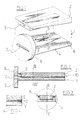
- Figure 1 shows a sealing element 1 that is suitable for feeding through several wires such as steel wires at the same time.
- the sealing element 1 comprises a casing that consists of the parts 2 and 4, the casing part 2 comprising a bulge 3 and the casing part 4 a hollow 5.
- the bulge 3 and the hollow 5 fit together; a resilient sealing means 8 is present in the casing part 4 for the sealing conjunction of the sheet-shaped parts 2 and 4.
- the bulge 3 and the hollow 5 are adjusted to each other in such a way that a free cross-sectional area is left for feeding wires through that connects with the feed-through aperture 7 made in the flange 6 that is attached onto or into the wall of a vacuum apparatus.
- the sheet-shaped casing part 2 is removed from the sheet-shaped casing part 4; the size of the aperture 7 is such that several wires can be fed through effortlessly.
- the sheet-shaped part 2 is put back in its place and attached in sealing relation onto the sheet-shaped casing part 4 with the aid of suitable means.
- the means of attachment can consist of simple screws; it is also possible to use clamping means that are simple to operate and with which a sealing conjunction of the casing parts 2 and 4 can be effected by a simple movement of the hand.
- the free cross-sectional area can be varied as well.
- spacers or distance pieces are used to regulate the cross-sectional area.
- Figure 2 is a sectional representation of the sealing element 1 of figure 1; the same parts are indicated with the same reference numbers.
- the attachment side of the sealing element is indicated with 9; the opposite side is indicated with 10.
- the sealing means 8 is fitted in a groove that extends over three of the four perimeter sides of the casing leaving on one perimeter side only a free cross-sectional area connected to the ambient air through which a number of wires can be fed.
- Figure 3 represents a section through the sealing element of fig. 1 and 2 along line III-III′ in figure 2.
- the sealing element on the side with the smallest cross-sectional area i.e. the side opposite the attachment side of the sealing element
- wear-resistant inserts 11 and 12 with which a wearing out of said part with the smallest cross-sectional area is prevented.
- the sealing element described hereinbefore can be applied when treating wire-shaped material in a vacuum apparatus.
- a vacuum apparatus is to be understood as referring to an apparatus that can carry out a treatment at a pressure that is lower than the atmospheric pressure and as regards the nature of the treatments, the treatments in mind are treatments such as vacuum coating, cathode sputtering, plasma deposition, sputter etching etc.
- sealing element has been described mainly as sealing element for application with wire-shaped material.
Landscapes
- Chemical & Material Sciences (AREA)
- Engineering & Computer Science (AREA)
- Materials Engineering (AREA)
- Mechanical Engineering (AREA)
- Metallurgy (AREA)
- Organic Chemistry (AREA)
- Chemical Kinetics & Catalysis (AREA)
- Thermal Sciences (AREA)
- Physics & Mathematics (AREA)
- Crystallography & Structural Chemistry (AREA)
- General Chemical & Material Sciences (AREA)
- Physical Vapour Deposition (AREA)
- Chemical Vapour Deposition (AREA)
- Sealing Devices (AREA)
- Sheet Holders (AREA)
- Gasket Seals (AREA)
Abstract
Description
- The invention relates in the first instance to a sealing element to be applied when feeding at least one elongated object such as wire, strip foil, bundles of wire through the wall of a vacuum apparatus, at least comprising a tubular casing that can be attached in sealing relation in the wall of the vacuum apparatus and which has an inside cross-sectional area that is larger than the cross-sectional area of the elongated object.
- Such a sealing element for application with a wire is known from the Dutch patent application 8602661 or European patent application No. 0266818 of the present applicant.
- In said application is described a sealing element that can be fitted into the wall of a vacuum apparatus, the wire being fed through a casing the length and the free surface of which are dimensioned in such a way that when feeding a wire through, the leakage of ambient air into the interior of the apparatus is reduced in such a way that the pumps connected to the vacuum apparatus, which have a normal, sufficient capacity, are well able to attain and maintain the required vacuum.
- It has been found when applying such a sealing element that the required length of the casing can be so long that major practical difficulties are encountered when leading a wire in at one side of the apparatus and leading it out at the other side, as is necessary in the case of wire rupture for instance, which has a detrimental effect on a good production process.
- The European patent publication 0272710 deals with a feed-through and sealing element for application in the wall of a vacuum chamber, which element comprises two detachable parts such as a split drawing die. The two parts are pressed against each other under a spring load and abut in this manner in a sealing relation thereby maintaining a free cross sectional area.
- A similar sealing element is also known from the French patent 1.545.284. However the free cross sectional area has a rectangular shape. The wall of the feed-through area comprises an elastic liner which is subjected at its outside to a pressure cushion load.
- Besides the fact that the parts of the feed through device according to these two prior art documents are not designed for easy assembly and disassembly, the cross sectional area of the passage for the elongated object is not necessarily constant during operation. Indeed the resilient spring or pressure cushion loading enables a temporary expansion of this area as suggested e.g. in column 1 l.47 to 54 of EP 272710A1 thereby increasing temporarily the amount of air inflow to the vacuum chamber.
- It is the object of the present invention to provide a solution to said drawback and it is to that end characterised in that the above described sealing element in accordance with the invention, the casing comprises at least two detachable parts that abut in sealing relation, leaving a free space interbetween them for allowing an elongated object to pass through easily, one part comprising a hollow or recess and the other part a bulge or projection fitting into said recess, thereby forming said free space which tapers down from the attachment side towards the opposite side.
- The application of a casing that consists of several parts allows a wire to be fed through very simply and quickly in the event of a wire rupture but also when starting the vacuum method. A simple laying-in of the wire can take place by removing one part of the casing, while the leading-out at the other side also becomes very simple by removing a part of the casing; the closing, too, can take place very simply and quickly.
- As will become clear later, the free cross-sectional area of the casing is relatively large at the place of attachment of the vacuum apparatus so that the feeding-through is in no way hampered there. If so desired, even relatively thick, rigid wires or tubes can be used when feeding through, so that no obstructions are met with inside the vacuum apparatus either.
- In the embodiment of the sealing element in accordance with the invention, the free cross-sectional area gradually decreases in the direction of the side opposite the attachment side. as stated in claim 1.
- By applying such a taper in free cross-sectional area from the attachment side to the other side of the casing, a further increase in the resistance against inflow of air is obtained.
- The description given hereinbefore started from the assumption that the sealing element is applied when loading one single wire into and out of a vacuum apparatus.
- In many cases, it will be desirable to feed several wires through a vacuum apparatus at the same time ; to that end, the sealing element in accordance with the invention is carried out as indicated in
claim 2.
By carrying out the casing parts of the sealing element in the shape of sheets and by having the sheet-shaped parts abut in sealing relation through the insertion of a resilient sealing means, it is obtained that the inflow of ambient air only takes place via the remaining free surface at the side opposite the attachment side. - Said free surface is the difference between the free surface left vacant by the construction and the total surface that corresponds to the cross-sectional area of the wires fed through.
- One sheet-shaped part of the casing then comprises a hollow, whereas the other part of the casing comprises a bulge that fits the hollow. The hollow and the bulge can be adjusted to each other in such a way that either a free cross-sectional area is obtained that is constant over the whole length of the casing; also, such a version of the hollow and the bulge can be present that the free cross-sectional area for feeding wire through decreases in the direction of the side of the casing opposite the attachment side.
- A certain degree of wear of the casing material can occur when feeding wire through the relatively narrow aperture at the side opposite the attachment side.
- With very great advantage in order to reduce wear, the side opposite the attachment side is provided with detachably mounted inserts between which is a free cross-sectional area for feeding through several wires. In particular, these inserts can be made of a wear-resistant material such as silicon carbide, tungsten carbide, aluminium oxide and the like.
- The invention also relates to a vacuum apparatus for the treatment of wire-shaped material provided with one or more sealing elements for continuously leading wire material into and out of the vacuum apparatus, characterised in that one or more sealing elements are applied as described hereinbefore in accordance with the invention.
- The invention will hereinafter be described with reference to the drawing, in which:
- fig. 1
- represents a perspective view of a sealing element in accordance with the invention, the sheet-shaped parts of the element being detached from each other;
- fig. 2
- represents a section along line II-II′ in fig. 3 through the sealing element in accordance with the invention;
- fig. 3
- represents a section along line III-III′ through the sealing element according of fig. 2; and
- fig. 4
- is a partial sectional view of a sealing element that is provided with wear-resistant inserts.
- Figure 1 shows a sealing element 1 that is suitable for feeding through several wires such as steel wires at the same time.
- The sealing element 1 comprises a casing that consists of the
parts casing part 2 comprising abulge 3 and the casing part 4 a hollow 5. Thebulge 3 and the hollow 5 fit together; a resilient sealing means 8 is present in thecasing part 4 for the sealing conjunction of the sheet-shaped parts - The
bulge 3 and the hollow 5 are adjusted to each other in such a way that a free cross-sectional area is left for feeding wires through that connects with the feed-through aperture 7 made in theflange 6 that is attached onto or into the wall of a vacuum apparatus.
When wire is fed through, the sheet-shaped casing part 2 is removed from the sheet-shaped casing part 4; the size of the aperture 7 is such that several wires can be fed through effortlessly. When the wire or wires have been fed through the vacuum apparatus and a sealing element at the other side of the apparatus, auxiliary means being used if so desired, the sheet-shaped part 2 is put back in its place and attached in sealing relation onto the sheet-shaped casing part 4 with the aid of suitable means. The means of attachment can consist of simple screws; it is also possible to use clamping means that are simple to operate and with which a sealing conjunction of thecasing parts - By varying the diameter of the sealing means 8, the free cross-sectional area can be varied as well. Preferably, however, spacers or distance pieces are used to regulate the cross-sectional area.
- Figure 2 is a sectional representation of the sealing element 1 of figure 1; the same parts are indicated with the same reference numbers. The attachment side of the sealing element is indicated with 9; the opposite side is indicated with 10. The
sealing means 8 is fitted in a groove that extends over three of the four perimeter sides of the casing leaving on one perimeter side only a free cross-sectional area connected to the ambient air through which a number of wires can be fed. - In figure 2 is shown that the free cross-sectional area of the space left between the
sheets opposite side 10. - Figure 3 represents a section through the sealing element of fig. 1 and 2 along line III-III′ in figure 2.
- Here too, the location of the sealing means 8 is clearly visible.
- Finally, in figure 4 is indicated that the sealing element on the side with the smallest cross-sectional area (i.e. the side opposite the attachment side of the sealing element) is provided with wear-
resistant inserts
The sealing element described hereinbefore can be applied when treating wire-shaped material in a vacuum apparatus. In this context, a vacuum apparatus is to be understood as referring to an apparatus that can carry out a treatment at a pressure that is lower than the atmospheric pressure and as regards the nature of the treatments, the treatments in mind are treatments such as vacuum coating, cathode sputtering, plasma deposition, sputter etching etc. - In the above and foregoing, the sealing element has been described mainly as sealing element for application with wire-shaped material.
- It will be clear that in particular the above described sealing element for application with several wires at the same time, can also be successfully applied for feeding a band or strip-shaped material through a vacuum apparatus. Excellent results are also obtained when treating such material that deviates from the wire shape with the aid of the sealing element in accordance with the invention.
Claims (10)
- A sealing element (1) for attachment in the wall of a vacuum apparatus and for feeding at least one elongated object, through said wall, said element (1) having an attachment side (9) and an opposite side (10) and comprising at least two detachable casing parts (2, 4) that abut in sealing relation thereby leaving a free space interbetween them for allowing said elongated object to pass through, characterized in that one casing part (4) comprises a hollow or recess (5) and the other part (2) comprises a bulge or projection (3) fitting into said recess (5) thereby forming said free space which tapers down from the attachment side (9) towards the opposite side (10).
- A sealing element according to claim 1 wherein the cross section of the free space, perpendicular to the longitudinal direction of the elongated object, is rectangular.
- A sealing element according to claim 1 or 2 whereby the casing parts (2, 4) abut in sealing relation by the insertion of a sealing means (8) that extends over the perimeter sides of the casing leaving only the opposite side (10) free.
- A sealing element according to claim 3, whereby said sealing means (8) comprises a resilient strip inserted into a groove extending on said perimeter sides.
- A sealing element according to claim 3 or 4 comprising further attachment or clamping means to effect the sealing relation between casing parts (2, 4) with an adjustable free space interbetween said parts.
- A sealing element according to claim 1 wherein on the side (10) opposite the attachment side (9) the casing is provided with detachably mounted inserts (11, 12) leaving the free space interbetween.
- A sealing element in accordance with claim 6, wherein the inserts (11, 12) are made of wear-resistant material.
- A vacuum apparatus for the treatment of elongated objects provided with one or more sealing elements for continuously passing said objects into and out of the apparatus and wherein one or more sealing elements are mounted in accordance with any of the claims 1 to 7.
- A vacuum apparatus according to claim 8 for vacuum coating, cathode sputtering, plasma deposition or sputter etching of the objects.
- A vacuum apparatus according to claim 8 or 9 for the treatment of several wires at the same time.
Applications Claiming Priority (2)
| Application Number | Priority Date | Filing Date | Title |
|---|---|---|---|
| NL8802822 | 1988-11-16 | ||
| NL8802822A NL8802822A (en) | 1988-11-16 | 1988-11-16 | SEALING ELEMENT FOR TRANSITING AT LEAST AN ELECTROUS OBJECT SUCH AS WIRE AND VACUUM DEVICE EQUIPPED WITH ONE OR MORE SEALING ELEMENTS. |
Publications (2)
| Publication Number | Publication Date |
|---|---|
| EP0370542A1 EP0370542A1 (en) | 1990-05-30 |
| EP0370542B1 true EP0370542B1 (en) | 1995-01-25 |
Family
ID=19853237
Family Applications (1)
| Application Number | Title | Priority Date | Filing Date |
|---|---|---|---|
| EP89202667A Expired - Lifetime EP0370542B1 (en) | 1988-11-16 | 1989-10-23 | Sealing element for feeding through at least one elongated object such as wire and a vacuum apparatus provided with one or more of such sealing elements |
Country Status (8)
| Country | Link |
|---|---|
| US (1) | US5050416A (en) |
| EP (1) | EP0370542B1 (en) |
| JP (1) | JP2918583B2 (en) |
| AT (1) | ATE117737T1 (en) |
| CA (1) | CA2001578A1 (en) |
| DE (1) | DE68920832T2 (en) |
| ES (1) | ES2070896T3 (en) |
| NL (1) | NL8802822A (en) |
Families Citing this family (9)
| Publication number | Priority date | Publication date | Assignee | Title |
|---|---|---|---|---|
| US5157851A (en) * | 1991-10-02 | 1992-10-27 | United Solar Systems Corporation | Pinching gate valve |
| US7247229B2 (en) | 1999-06-28 | 2007-07-24 | Eltech Systems Corporation | Coatings for the inhibition of undesirable oxidation in an electrochemical cell |
| US8138443B2 (en) * | 2008-10-20 | 2012-03-20 | Honeywell International Inc. | Sealing systems |
| EP2281921A1 (en) * | 2009-07-30 | 2011-02-09 | Nederlandse Organisatie voor toegepast -natuurwetenschappelijk onderzoek TNO | Apparatus and method for atomic layer deposition. |
| EP2360293A1 (en) | 2010-02-11 | 2011-08-24 | Nederlandse Organisatie voor toegepast -natuurwetenschappelijk onderzoek TNO | Method and apparatus for depositing atomic layers on a substrate |
| EP2362002A1 (en) | 2010-02-18 | 2011-08-31 | Nederlandse Organisatie voor toegepast -natuurwetenschappelijk onderzoek TNO | Continuous patterned layer deposition |
| EP2362411A1 (en) | 2010-02-26 | 2011-08-31 | Nederlandse Organisatie voor toegepast -natuurwetenschappelijk onderzoek TNO | Apparatus and method for reactive ion etching |
| US8707748B2 (en) * | 2010-07-01 | 2014-04-29 | Siemens Industry, Inc. | Turn down apparatus |
| CN102443818B (en) | 2010-10-08 | 2016-01-13 | 水之星公司 | Multi-layer mixed metal oxide electrode and manufacture method thereof |
Family Cites Families (10)
| Publication number | Priority date | Publication date | Assignee | Title |
|---|---|---|---|---|
| US1948485A (en) * | 1930-06-30 | 1934-02-27 | Fansteel Prod Co Inc | Method of drawing wire |
| US2006931A (en) * | 1934-03-01 | 1935-07-02 | Gen Electric | Electrical insulator |
| US2968505A (en) * | 1957-05-03 | 1961-01-17 | Scaramucci Domer | Long life cylindrical packing for oil savers and like devices |
| FR1545284A (en) * | 1967-11-24 | 1968-11-08 | Hochvakuum Dresden Veb | Spraying device by spraying on strips |
| US3669065A (en) * | 1971-03-15 | 1972-06-13 | United Aircraft Corp | Reactor seal |
| GB1512837A (en) * | 1975-06-24 | 1978-06-01 | Electricity Council | Seals for the passage of wire between regions of different pressure |
| FR2315645A2 (en) * | 1973-09-06 | 1977-01-21 | Electricity Council | Sealed reduced pressure appts. for treating wire |
| US3952568A (en) * | 1974-09-04 | 1976-04-27 | The Electricity Council | Vacuum processing of rod, wire or strip material |
| NL8602661A (en) * | 1986-10-23 | 1988-05-16 | Bekaert Sa Nv | TRANSIT ELEMENT FOR VACUUM EQUIPMENT AND EQUIPMENT EQUIPPED WITH SUCH TRANSIT ELEMENTS. |
| NL8602660A (en) * | 1986-10-23 | 1988-05-16 | Bekaert Sa Nv | TRANSIT ELEMENT FOR APPLICATION IN A VACUUM DEVICE AND VACUUM DEVICE EQUIPPED WITH ONE OR MORE OF SUCH TRANSIT ELEMENTS. |
-
1988
- 1988-11-16 NL NL8802822A patent/NL8802822A/en not_active Application Discontinuation
-
1989
- 1989-10-23 AT AT89202667T patent/ATE117737T1/en not_active IP Right Cessation
- 1989-10-23 EP EP89202667A patent/EP0370542B1/en not_active Expired - Lifetime
- 1989-10-23 ES ES89202667T patent/ES2070896T3/en not_active Expired - Lifetime
- 1989-10-23 DE DE68920832T patent/DE68920832T2/en not_active Expired - Fee Related
- 1989-10-26 CA CA002001578A patent/CA2001578A1/en not_active Abandoned
- 1989-11-02 US US07/430,288 patent/US5050416A/en not_active Expired - Lifetime
- 1989-11-14 JP JP1294100A patent/JP2918583B2/en not_active Expired - Lifetime
Also Published As
| Publication number | Publication date |
|---|---|
| JPH02213470A (en) | 1990-08-24 |
| EP0370542A1 (en) | 1990-05-30 |
| ES2070896T3 (en) | 1995-06-16 |
| ATE117737T1 (en) | 1995-02-15 |
| DE68920832T2 (en) | 1995-07-06 |
| CA2001578A1 (en) | 1990-05-16 |
| NL8802822A (en) | 1990-06-18 |
| DE68920832D1 (en) | 1995-03-09 |
| US5050416A (en) | 1991-09-24 |
| JP2918583B2 (en) | 1999-07-12 |
Similar Documents
| Publication | Publication Date | Title |
|---|---|---|
| US5050416A (en) | Sealing element for feeding through at least one elongated object such as wire and a vacuum apparatus provided with one or more of sealing elements | |
| US3642132A (en) | Adjustable hard ceramic underflow outlet for hydrocyclone | |
| US2966373A (en) | Tubular inserts | |
| EP0792951A4 (en) | Vacuum chamber made of aluminum or its alloy, and surface treatment and material for the vacuum chamber | |
| EP1175976A3 (en) | Panel cutting apparatus | |
| EP0929093A3 (en) | Plasma processor for large workpieces | |
| NO311731B1 (en) | Slot configuration for a pressure belt | |
| JP2006205739A (en) | Apparatus for variable limitation barrier of flat flow channel and method for extracting "massebahn" with variable geometric shape | |
| US2956301A (en) | Web cleaning apparatus | |
| EP0585109A3 (en) | N-acetylglucosaminyl transferase, gene coding therefor, corresponding vectors and transformed hosts, processes for production thereof | |
| US4436252A (en) | Tension shaft for winding frames | |
| KR19990008741A (en) | Roller structure for rolling the band | |
| GB2276339B (en) | Screening Apparatus | |
| EP0364215A2 (en) | Plasma etching apparatus | |
| WO1997025561A3 (en) | Subsea flexible pipe | |
| AU701094B2 (en) | Tool component | |
| GB2060718A (en) | Reed baulk unit | |
| US7772576B2 (en) | Shielding assembly for semiconductor manufacturing apparatus and method of using the same | |
| EP0266818B1 (en) | Feed-through element for vacuum apparatus and apparatus provided with such feed-through elements | |
| US4790165A (en) | Feed-through element for a vacuum apparatus | |
| US4787227A (en) | Feed-through element for a vacuum apparatus | |
| US2820487A (en) | Grid fabrication method | |
| ITMI950517A1 (en) | APPARATUS FOR BEVELING PIPES | |
| EP0326085B1 (en) | Production of nozzle member | |
| EP0802346A3 (en) | Gas cylinder |
Legal Events
| Date | Code | Title | Description |
|---|---|---|---|
| PUAI | Public reference made under article 153(3) epc to a published international application that has entered the european phase |
Free format text: ORIGINAL CODE: 0009012 |
|
| AK | Designated contracting states |
Kind code of ref document: A1 Designated state(s): AT BE CH DE ES FR GB GR IT LI LU NL SE |
|
| 17P | Request for examination filed |
Effective date: 19901112 |
|
| 17Q | First examination report despatched |
Effective date: 19921012 |
|
| GRAA | (expected) grant |
Free format text: ORIGINAL CODE: 0009210 |
|
| AK | Designated contracting states |
Kind code of ref document: B1 Designated state(s): AT BE CH DE ES FR GB GR IT LI LU NL SE |
|
| PG25 | Lapsed in a contracting state [announced via postgrant information from national office to epo] |
Ref country code: LI Effective date: 19950125 Ref country code: GR Free format text: LAPSE BECAUSE OF FAILURE TO SUBMIT A TRANSLATION OF THE DESCRIPTION OR TO PAY THE FEE WITHIN THE PRESCRIBED TIME-LIMIT Effective date: 19950125 Ref country code: CH Effective date: 19950125 |
|
| REF | Corresponds to: |
Ref document number: 117737 Country of ref document: AT Date of ref document: 19950215 Kind code of ref document: T |
|
| REF | Corresponds to: |
Ref document number: 68920832 Country of ref document: DE Date of ref document: 19950309 |
|
| ITF | It: translation for a ep patent filed | ||
| REG | Reference to a national code |
Ref country code: CH Ref legal event code: PL |
|
| ET | Fr: translation filed | ||
| REG | Reference to a national code |
Ref country code: ES Ref legal event code: FG2A Ref document number: 2070896 Country of ref document: ES Kind code of ref document: T3 |
|
| PLBE | No opposition filed within time limit |
Free format text: ORIGINAL CODE: 0009261 |
|
| STAA | Information on the status of an ep patent application or granted ep patent |
Free format text: STATUS: NO OPPOSITION FILED WITHIN TIME LIMIT |
|
| 26N | No opposition filed | ||
| PGFP | Annual fee paid to national office [announced via postgrant information from national office to epo] |
Ref country code: SE Payment date: 19960830 Year of fee payment: 8 |
|
| PGFP | Annual fee paid to national office [announced via postgrant information from national office to epo] |
Ref country code: AT Payment date: 19960902 Year of fee payment: 8 |
|
| REG | Reference to a national code |
Ref country code: FR Ref legal event code: ST |
|
| PGFP | Annual fee paid to national office [announced via postgrant information from national office to epo] |
Ref country code: NL Payment date: 19960910 Year of fee payment: 8 |
|
| PGFP | Annual fee paid to national office [announced via postgrant information from national office to epo] |
Ref country code: ES Payment date: 19961011 Year of fee payment: 8 |
|
| REG | Reference to a national code |
Ref country code: FR Ref legal event code: RN |
|
| REG | Reference to a national code |
Ref country code: FR Ref legal event code: D3 |
|
| PG25 | Lapsed in a contracting state [announced via postgrant information from national office to epo] |
Ref country code: AT Free format text: LAPSE BECAUSE OF NON-PAYMENT OF DUE FEES Effective date: 19971023 |
|
| PG25 | Lapsed in a contracting state [announced via postgrant information from national office to epo] |
Ref country code: SE Free format text: LAPSE BECAUSE OF NON-PAYMENT OF DUE FEES Effective date: 19971024 Ref country code: ES Free format text: LAPSE BECAUSE OF NON-PAYMENT OF DUE FEES Effective date: 19971024 |
|
| PG25 | Lapsed in a contracting state [announced via postgrant information from national office to epo] |
Ref country code: NL Free format text: LAPSE BECAUSE OF NON-PAYMENT OF DUE FEES Effective date: 19980501 |
|
| NLV4 | Nl: lapsed or anulled due to non-payment of the annual fee |
Effective date: 19980501 |
|
| EUG | Se: european patent has lapsed |
Ref document number: 89202667.5 |
|
| REG | Reference to a national code |
Ref country code: GB Ref legal event code: IF02 |
|
| PGFP | Annual fee paid to national office [announced via postgrant information from national office to epo] |
Ref country code: FR Payment date: 20020912 Year of fee payment: 14 |
|
| PGFP | Annual fee paid to national office [announced via postgrant information from national office to epo] |
Ref country code: DE Payment date: 20020914 Year of fee payment: 14 |
|
| PGFP | Annual fee paid to national office [announced via postgrant information from national office to epo] |
Ref country code: GB Payment date: 20020916 Year of fee payment: 14 |
|
| PGFP | Annual fee paid to national office [announced via postgrant information from national office to epo] |
Ref country code: LU Payment date: 20020917 Year of fee payment: 14 Ref country code: BE Payment date: 20020917 Year of fee payment: 14 |
|
| PG25 | Lapsed in a contracting state [announced via postgrant information from national office to epo] |
Ref country code: LU Free format text: LAPSE BECAUSE OF NON-PAYMENT OF DUE FEES Effective date: 20031023 Ref country code: GB Free format text: LAPSE BECAUSE OF NON-PAYMENT OF DUE FEES Effective date: 20031023 |
|
| PG25 | Lapsed in a contracting state [announced via postgrant information from national office to epo] |
Ref country code: BE Free format text: LAPSE BECAUSE OF NON-PAYMENT OF DUE FEES Effective date: 20031031 |
|
| REG | Reference to a national code |
Ref country code: ES Ref legal event code: FD2A Effective date: 19981113 |
|
| BERE | Be: lapsed |
Owner name: S.A. *BEKAERT N.V. Effective date: 20031031 |
|
| PG25 | Lapsed in a contracting state [announced via postgrant information from national office to epo] |
Ref country code: DE Free format text: LAPSE BECAUSE OF NON-PAYMENT OF DUE FEES Effective date: 20040501 |
|
| GBPC | Gb: european patent ceased through non-payment of renewal fee |
Effective date: 20031023 |
|
| PG25 | Lapsed in a contracting state [announced via postgrant information from national office to epo] |
Ref country code: FR Free format text: LAPSE BECAUSE OF NON-PAYMENT OF DUE FEES Effective date: 20040630 |
|
| REG | Reference to a national code |
Ref country code: FR Ref legal event code: ST |
|
| PG25 | Lapsed in a contracting state [announced via postgrant information from national office to epo] |
Ref country code: IT Free format text: LAPSE BECAUSE OF NON-PAYMENT OF DUE FEES;WARNING: LAPSES OF ITALIAN PATENTS WITH EFFECTIVE DATE BEFORE 2007 MAY HAVE OCCURRED AT ANY TIME BEFORE 2007. THE CORRECT EFFECTIVE DATE MAY BE DIFFERENT FROM THE ONE RECORDED. Effective date: 20051023 |