EP0370313B1 - Heat transfer method in a glass sheet bending furnace and bending furnace - Google Patents
Heat transfer method in a glass sheet bending furnace and bending furnace Download PDFInfo
- Publication number
- EP0370313B1 EP0370313B1 EP89120722A EP89120722A EP0370313B1 EP 0370313 B1 EP0370313 B1 EP 0370313B1 EP 89120722 A EP89120722 A EP 89120722A EP 89120722 A EP89120722 A EP 89120722A EP 0370313 B1 EP0370313 B1 EP 0370313B1
- Authority
- EP
- European Patent Office
- Prior art keywords
- sections
- section
- cooling
- successive
- heating
- Prior art date
- Legal status (The legal status is an assumption and is not a legal conclusion. Google has not performed a legal analysis and makes no representation as to the accuracy of the status listed.)
- Expired - Lifetime
Links
- 239000011521 glass Substances 0.000 title claims abstract description 40
- 238000005452 bending Methods 0.000 title claims abstract description 25
- 238000000034 method Methods 0.000 title claims abstract description 12
- 238000001816 cooling Methods 0.000 claims abstract description 41
- 238000010438 heat treatment Methods 0.000 claims abstract description 32
- 238000005422 blasting Methods 0.000 claims abstract 2
- 230000004888 barrier function Effects 0.000 claims description 2
- 238000005192 partition Methods 0.000 claims description 2
- 238000007789 sealing Methods 0.000 claims description 2
- 239000007789 gas Substances 0.000 description 4
- 230000005855 radiation Effects 0.000 description 2
- 230000000630 rising effect Effects 0.000 description 2
- 230000003247 decreasing effect Effects 0.000 description 1
- 238000004519 manufacturing process Methods 0.000 description 1
- 230000000284 resting effect Effects 0.000 description 1
- 229920002994 synthetic fiber Polymers 0.000 description 1
Images


Classifications
-
- C—CHEMISTRY; METALLURGY
- C03—GLASS; MINERAL OR SLAG WOOL
- C03B—MANUFACTURE, SHAPING, OR SUPPLEMENTARY PROCESSES
- C03B23/00—Re-forming shaped glass
- C03B23/02—Re-forming glass sheets
- C03B23/023—Re-forming glass sheets by bending
- C03B23/025—Re-forming glass sheets by bending by gravity
- C03B23/0258—Gravity bending involving applying local or additional heating, cooling or insulating means
-
- C—CHEMISTRY; METALLURGY
- C03—GLASS; MINERAL OR SLAG WOOL
- C03B—MANUFACTURE, SHAPING, OR SUPPLEMENTARY PROCESSES
- C03B25/00—Annealing glass products
- C03B25/04—Annealing glass products in a continuous way
- C03B25/06—Annealing glass products in a continuous way with horizontal displacement of the glass products
- C03B25/08—Annealing glass products in a continuous way with horizontal displacement of the glass products of glass sheets
-
- C—CHEMISTRY; METALLURGY
- C03—GLASS; MINERAL OR SLAG WOOL
- C03B—MANUFACTURE, SHAPING, OR SUPPLEMENTARY PROCESSES
- C03B29/00—Reheating glass products for softening or fusing their surfaces; Fire-polishing; Fusing of margins
- C03B29/04—Reheating glass products for softening or fusing their surfaces; Fire-polishing; Fusing of margins in a continuous way
- C03B29/06—Reheating glass products for softening or fusing their surfaces; Fire-polishing; Fusing of margins in a continuous way with horizontal displacement of the products
- C03B29/08—Glass sheets
-
- Y—GENERAL TAGGING OF NEW TECHNOLOGICAL DEVELOPMENTS; GENERAL TAGGING OF CROSS-SECTIONAL TECHNOLOGIES SPANNING OVER SEVERAL SECTIONS OF THE IPC; TECHNICAL SUBJECTS COVERED BY FORMER USPC CROSS-REFERENCE ART COLLECTIONS [XRACs] AND DIGESTS
- Y02—TECHNOLOGIES OR APPLICATIONS FOR MITIGATION OR ADAPTATION AGAINST CLIMATE CHANGE
- Y02P—CLIMATE CHANGE MITIGATION TECHNOLOGIES IN THE PRODUCTION OR PROCESSING OF GOODS
- Y02P40/00—Technologies relating to the processing of minerals
- Y02P40/50—Glass production, e.g. reusing waste heat during processing or shaping
- Y02P40/57—Improving the yield, e-g- reduction of reject rates
Definitions
- the present invention relates to a heat transfer method in a glass sheet bending furnace, comprising a top array of successive heating sections and a bottom array of successive cooling sections, whereby the glass sheets are placed upon bending moulds supported by carrier wagons and the successive wagons are advanced on the top conveyor track from one heating section to the next and, correspondingly, on the bottom conveyor track from one cooling section to the next and heat is transferred from the bent, hot glasses and moulds in said cooling sections to the non-bent, colder glasses and moulds in said heating sections.
- the invention relates also to a glass sheet bending furnace for carrying out the method, said furnace comprising a top array of successive heating sections and a bottom array of successive cooling sections as well as, respectively, a top and a bottom conveyor track for the carrrier wagons of bending moulds.
- FR-A-15 84 600 discloses a glass sheet bending furnace comprising a system of gas conduits disposed in the area of the furnace in which the bending is effected for controlling the bending temperature. Hot gas from an exterior source and a cold gas sucked from a cold area of the furnace are provided by means of the conduits. The bending temperature is controlled by mixing these two gases at different ratios.
- An object of the invention is to provide an improved heat transfer method for further intensifying the transfer of heat from hot glass to colder glass as well as from a hot mould to a colder mould.
- the invention can be used for accelerating the cooling rate of glass sheets to be cooled, for accelerating the heating rate of glass sheets to be heated, for more effective exploitation of the thermal energy of glass sheets to be cooled, for retrieving glass sheets from the furnace colder than heretofore and, in addition, the invention can accomplish a more uniform cooling rate and a more uniform heating rate for glass sheets.
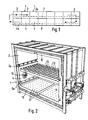
- the bending furnace shown in fig. 1 includes a top or upper array of successive heating sections 2 and a bottom or lower array of successive cooling sections 4.
- the arrows indicate the traveling path of glass sheets along an upper conveyor track 7 and a lower conveyor track 8.
- the first heating sections 2 are so-called preheating sections which are followed by actual heating sections and then by one or two bending sections 3.
- At least the preheating sections 2 along with cooling sections 4 therebelow consist of section units 1 as shown in fig. 2.
- the glass sheets are placed upon bending moulds 6 supported by carrier wagons 5 shown in fig. 3.
- the rails 5a of carrier wagons 5 are carried on top of upper track rollers 7a and, respectively, on top of lower track rollers 8a.
- the successive wagons 5 are advanced on upper conveyor track 7 from one heating section 2 to the next.
- said wagons 5 are advanced from one cooling section 4 to the next.
- heat is transferred from the bent, hot glasses HG in cooling sections 4 to non-bent, colder glasses CG in heating sections 2.
- the heat is transferred by means of radiation and gravitational convection.
- the ceiling and floors of heating section 2 as well as those of cooling section 4 are fitted with blast air supply boxes 13, 15, 16 provided with blast orifices 14, 17 which are distributed substantially over the entire surface area of the sections.
- Both side walls of cooling sections 4 are fitted with fans 11 whose suction inlets 10 open into the cooling section.
- the pressure sides of fans 11 are connected by air passages 12 to said supply boxes 13, 15, 16.
- the fans 11 are used for the continuous suction of air from cooling section 4, whereby a hot glass sheet HG delivers heat into said air upon cooling. From the blast orifices 14, 17 of supply boxes 13, 15, 16 the air discharges as substantially vertical blast jets to the top and bottom surfaces of glass sheet CG as well as to the top and bottom surfaces of glass sheet HG. The air coming into section 2 finds its way back into section 4 through the gaps between supply boxes 13.
- hot air is discharged from at least one section 2 and, respectively, at least one section 4 is supplied with cold replacement air which in the lengthwise direction of the furnace is distributed from one section 4 to another section 4.
- cold replacement air is supplied into section 4a and some hot air is discharged from section 2a (fig. 1).
- the heat transfer arrangement of the invention is typically carried out e.g. in three heating sections (depending on furnace capacity) and respectively in as many of the last cooling sections 4.
- the temperature curve of fig. 4 illustrates a situation in which the intensified heat transfer has been effected in three successive sections, indicated with ordinal numbers I, II and III.
- the curve indicates that in sections I, II and III, i.e. on the rising section of the curve, the glass sheet temperature increasing rate is initially very high whereby the final temperature of the section is reached quickly or, alternatively, the glass sheet takes a longer time to reach the final temperature of the section. Accordingly, on the falling section of the curve, the cooling proceeds in cooling sections I, II and III in a manner that the temperature decreasing rate is very high at the beginning of each cooling cycle.
- the temperature difference is indicated in fig. 4 with ⁇ T.
- the invention serves also to increase production capacity in that the furnace will be able to operate on the maximum capacity determined on the basis of time required for bending a glass sheet in bending section 3 (fig. 1).
- Fig. 3 illustrates flat rails 5a which run alongside wagons 5 and which carry wagons 5 resting upon conveyor rollers 7a.
- the end walls 18 of wagons 5 provide partitions between successive sections 2, 2 or 4, 4 whenever said wagons 5 are stopped inside the sections.
- a resilient sealing 19 which comes into contact with the edges of end walls 18 of the wagons and which is e.g. a brush made of artificial fibers and/or hair and which provides a barrier to the air flows between the successive sections. This makes it easier to maintain the temperature differences between successive heating sections 2.
- temperature differences between the superimposed sections should be equalized as effectively as possible according to the invention.
Landscapes
- Chemical & Material Sciences (AREA)
- Engineering & Computer Science (AREA)
- Materials Engineering (AREA)
- Organic Chemistry (AREA)
- Re-Forming, After-Treatment, Cutting And Transporting Of Glass Products (AREA)
- Tunnel Furnaces (AREA)
- Auxiliary Devices For And Details Of Packaging Control (AREA)
- Control Of El Displays (AREA)
- Glass Compositions (AREA)
- Solid-Sorbent Or Filter-Aiding Compositions (AREA)
Abstract
Description
- The present invention relates to a heat transfer method in a glass sheet bending furnace, comprising a top array of successive heating sections and a bottom array of successive cooling sections, whereby the glass sheets are placed upon bending moulds supported by carrier wagons and the successive wagons are advanced on the top conveyor track from one heating section to the next and, correspondingly, on the bottom conveyor track from one cooling section to the next and heat is transferred from the bent, hot glasses and moulds in said cooling sections to the non-bent, colder glasses and moulds in said heating sections.
- The invention relates also to a glass sheet bending furnace for carrying out the method, said furnace comprising a top array of successive heating sections and a bottom array of successive cooling sections as well as, respectively, a top and a bottom conveyor track for the carrrier wagons of bending moulds.
- As for the prior art, reference is made to the Proprietor's US Patent 4 497 645 which discloses the intensification of heat transfer through the wagon floors. In this prior art method, the transfer of heat is effected by means of radiation and gravitational convection.
- FR-A-15 84 600 discloses a glass sheet bending furnace comprising a system of gas conduits disposed in the area of the furnace in which the bending is effected for controlling the bending temperature. Hot gas from an exterior source and a cold gas sucked from a cold area of the furnace are provided by means of the conduits. The bending temperature is controlled by mixing these two gases at different ratios.
- An object of the invention is to provide an improved heat transfer method for further intensifying the transfer of heat from hot glass to colder glass as well as from a hot mould to a colder mould.
- This object is achieved by the method of claim 1 and the bending furnace of claim 4.
- Thus, the invention can be used for accelerating the cooling rate of glass sheets to be cooled, for accelerating the heating rate of glass sheets to be heated, for more effective exploitation of the thermal energy of glass sheets to be cooled, for retrieving glass sheets from the furnace colder than heretofore and, in addition, the invention can accomplish a more uniform cooling rate and a more uniform heating rate for glass sheets.
- The invention will now be described in more detail with reference made to the accompanying drawings, in which
- fig. 1 shows a bending furnace schematically in a side view.
- Fig. 2 shows a cutaway perspective view of one section of a furnace, including a top heating section and a bottom cooling section.
- Fig. 3 shows a cross-section of a bending furnace and
- fig. 4 is a graph showing the glass sheet temperature as a function of time, the successive sections being separated by vertical lines. The rising curve represents heating on the upper track and the falling curve represents cooling on the lower track.
- The bending furnace shown in fig. 1 includes a top or upper array of
successive heating sections 2 and a bottom or lower array of successive cooling sections 4. - The arrows indicate the traveling path of glass sheets along an
upper conveyor track 7 and alower conveyor track 8. Thefirst heating sections 2 are so-called preheating sections which are followed by actual heating sections and then by one or twobending sections 3. At least the preheatingsections 2 along with cooling sections 4 therebelow consist of section units 1 as shown in fig. 2. - The glass sheets are placed upon bending moulds 6 supported by carrier wagons 5 shown in fig. 3. The
rails 5a of carrier wagons 5 are carried on top ofupper track rollers 7a and, respectively, on top oflower track rollers 8a. The successive wagons 5 are advanced onupper conveyor track 7 from oneheating section 2 to the next. Correspondingly, onlower conveyor track 8 said wagons 5 are advanced from one cooling section 4 to the next. Thus, heat is transferred from the bent, hot glasses HG in cooling sections 4 to non-bent, colder glasses CG inheating sections 2. In the solution disclosed in US Patent 4 497 645, the heat is transferred by means of radiation and gravitational convection. - In this invention, the transfer of heat is intensified by means of the arrangement described hereinbelow.
- As shown in figs. 2 and 3, the ceiling and floors of
heating section 2 as well as those of cooling section 4 are fitted with blastair supply boxes blast orifices 14, 17 which are distributed substantially over the entire surface area of the sections. Both side walls of cooling sections 4 are fitted withfans 11 whosesuction inlets 10 open into the cooling section. The pressure sides offans 11 are connected byair passages 12 to saidsupply boxes - The
fans 11 are used for the continuous suction of air from cooling section 4, whereby a hot glass sheet HG delivers heat into said air upon cooling. From theblast orifices 14, 17 ofsupply boxes section 2 finds its way back into section 4 through the gaps betweensupply boxes 13. - In order to maintain thermal equilibrieum, hot air is discharged from at least one
section 2 and, respectively, at least one section 4 is supplied with cold replacement air which in the lengthwise direction of the furnace is distributed from one section 4 to another section 4. Most preferably, the cold replacement air is supplied intosection 4a and some hot air is discharged from section 2a (fig. 1). - The heat transfer arrangement of the invention is typically carried out e.g. in three heating sections (depending on furnace capacity) and respectively in as many of the last cooling sections 4.
- The temperature curve of fig. 4 illustrates a situation in which the intensified heat transfer has been effected in three successive sections, indicated with ordinal numbers I, II and III. The curve indicates that in sections I, II and III, i.e. on the rising section of the curve, the glass sheet temperature increasing rate is initially very high whereby the final temperature of the section is reached quickly or, alternatively, the glass sheet takes a longer time to reach the final temperature of the section. Accordingly, on the falling section of the curve, the cooling proceeds in cooling sections I, II and III in a manner that the temperature decreasing rate is very high at the beginning of each cooling cycle. By virtue of this, the glass coming out of the furnace has a temperature substantially lower than what it would have without the intensified heat transfer of the invention. The temperature difference is indicated in fig. 4 with ΔT. The invention serves also to increase production capacity in that the furnace will be able to operate on the maximum capacity determined on the basis of time required for bending a glass sheet in bending section 3 (fig. 1).
- Fig. 3 illustrates
flat rails 5a which run alongside wagons 5 and which carry wagons 5 resting uponconveyor rollers 7a. Theend walls 18 of wagons 5 provide partitions betweensuccessive sections successive heating sections 2 there is provided aresilient sealing 19 which comes into contact with the edges ofend walls 18 of the wagons and which is e.g. a brush made of artificial fibers and/or hair and which provides a barrier to the air flows between the successive sections. This makes it easier to maintain the temperature differences betweensuccessive heating sections 2. On the other hand, temperature differences between the superimposed sections should be equalized as effectively as possible according to the invention.
Claims (7)
- A heat transfer method in a glass sheet bending furnace, including a top array of successive heating sections (2) and a bottom array of successive cooling sections (4), whereby the glass sheets are placed upon bending molds (6) supported by carrier wagons (5) and successive wagons (5) are advanced on an upper conveyor track (7) from one heating section (2) to the next and, correspondingly, on a lower conveyor track (8) from one cooling section (4) to the next and heat is transferred from bent, hot glass (HG) in said cooling sections (4) to non-bent, cooler glasses (CG) in said heating sections (2),
characterized in that
in order to intensify said heat transfer, air is sucked from at least one cooling section (4) and blasted into the corresponding overlaying heating section (2) on either side of a glass sheet (CG) contained in said at least one heating section (2) and also back into the at least one cooling section on either side of a glass sheet (HG) contained in said at least one cooling section (4). - A method as set forth in claim 1,
characterized in that
the substantially vertical blast jets are directed to the opposite surfaces of a glass sheet from the ceiling and floor of said sections (2, 4), said jets being distributed over substantially the entire surface of the sections. - A method as set forth in claim 1 or 2,
characterized in that
the blast air is sucked from either side of said cooling sections (4). - A glass sheet bending furnace for carrying out the methods set forth in any of claims 1 to 3, said furnace including a top array of successive heating sections (2) and a bottom array of successive cooling sections (4) and, respectively, an upper and a lower conveyor track (7 and 8) for carrier wagons (5) of bending molds (6),
characterized in that
between at least one cooling section (4) and a corresponding overlaying heating section (2) there is a system of air passages (12) provided with a fan (11) in a manner that a suction inlet (10) of the air passage system is provided in said at least one cooling section (4) for sucking air from said at least one cooling section, and air jet blast orifices (14, 17) are provided in the ceiling and floor of said corresponding heating section as well as in the ceiling and floor of said at least one cooling section (2) for blasting said air into both said at least one heating section and said at least one cooling section. - A furnace as set forth in claim 4,
characterized in that
the ceiling and floor of each heating section (2), as well as those of each cooling section (4), are fitted with blast air supply boxes (13, 15, 16) provided with said blast orifices (14, 17) which are distributed over substantially the entire surface area of the sections. - A furnace as set forth in claim 4 or 5,
characterized in that
said fans (11), along with said suction inlets (10) thereof, are located on both side walls of said cooling sections (4). - A furnace as set forth in any of claims 4 to 6,
characterized in that
the end walls (18) of said wagons (5) provide partitions between successive sections (2,2 or 4,4), wherein at the junctions between successive sections there is provided a resilient sealing (19) which comes into contact with the edges of said end walls (18) of the wagons and which provides a barrier to the air flow between successive sections whenever said carrier wagons (5) are stopped inside the sections.
Priority Applications (1)
| Application Number | Priority Date | Filing Date | Title |
|---|---|---|---|
| AT89120722T ATE93501T1 (en) | 1988-11-24 | 1989-11-08 | HEAT EVALUATION IN A GLASS PANE BENDING FURNACE AND BENDING FURNACE. |
Applications Claiming Priority (2)
| Application Number | Priority Date | Filing Date | Title |
|---|---|---|---|
| FI885450 | 1988-11-24 | ||
| FI885450A FI81331C (en) | 1988-11-24 | 1988-11-24 | VAERMEOEVERFOERINGSFOERFARANDE I EN BOEJNINGSUGN FOER GLASSKIVOR OCH EN BOEJNINGSUGN. |
Publications (2)
| Publication Number | Publication Date |
|---|---|
| EP0370313A1 EP0370313A1 (en) | 1990-05-30 |
| EP0370313B1 true EP0370313B1 (en) | 1993-08-25 |
Family
ID=8527456
Family Applications (1)
| Application Number | Title | Priority Date | Filing Date |
|---|---|---|---|
| EP89120722A Expired - Lifetime EP0370313B1 (en) | 1988-11-24 | 1989-11-08 | Heat transfer method in a glass sheet bending furnace and bending furnace |
Country Status (10)
| Country | Link |
|---|---|
| US (1) | US4986842A (en) |
| EP (1) | EP0370313B1 (en) |
| JP (1) | JP2815428B2 (en) |
| CN (1) | CN1014600B (en) |
| AT (1) | ATE93501T1 (en) |
| AU (1) | AU619358B2 (en) |
| CA (1) | CA2001928C (en) |
| DE (1) | DE68908669T2 (en) |
| FI (1) | FI81331C (en) |
| RU (1) | RU2009107C1 (en) |
Families Citing this family (27)
| Publication number | Priority date | Publication date | Assignee | Title |
|---|---|---|---|---|
| FI84805C (en) * | 1990-03-30 | 1992-01-27 | Tamglass Oy | FOERFARANDE OCH FORMANORDNING FOER ATT BOEJA SVAORA FORMER PAO EN GLASSKIVA. |
| FI86054C (en) * | 1990-07-05 | 1992-07-10 | Tamglass Oy | Method and apparatus for bending glass sheet |
| FI87920C (en) * | 1991-04-26 | 1993-03-10 | Tamglass Eng Oy | ANORDING FOR BOILING AV EN AV KANTFORM UNDERSTOEDD GLASSKIVA |
| FI91244C (en) * | 1992-04-30 | 1994-06-10 | Tamglass Eng Oy | Method and apparatus for bending and curing glass sheet |
| FI91522C (en) * | 1992-09-18 | 1994-07-11 | Tamglass Eng Oy | Method and apparatus for bending glass sheets |
| DE69308715T2 (en) * | 1992-10-15 | 1997-06-19 | Tamglass Eng Oy | Method and furnace for bending glass sheets |
| FI91521C (en) * | 1992-10-15 | 1996-09-11 | Tamglass Eng Oy | Method for bending glass sheets |
| FI97292C (en) * | 1995-04-04 | 1996-11-25 | Tamglass Eng Oy | Method for transferring glass sheet transport carts in a glass sheet bending furnace and a glass sheet bending furnace |
| FI100397B (en) * | 1995-10-24 | 1997-11-28 | Glassrobots Oy | Heat transfer method in a bending oven for glass sheets and a bending oven |
| BR9612448A (en) * | 1996-01-19 | 1999-07-13 | Glasstech Inc | Apparatus for heating by forced convection and process to heat a glass slide in said apparatus |
| FI109199B (en) * | 2001-02-28 | 2002-06-14 | Tamglass Ltd Oy | Arrangement for bending glass plates |
| US6983104B2 (en) * | 2002-03-20 | 2006-01-03 | Guardian Industries Corp. | Apparatus and method for bending and/or tempering glass |
| FI116726B (en) * | 2002-06-12 | 2006-02-15 | Tamglass Ltd Oy | Device for bending glass sheets |
| FI20021131A7 (en) * | 2002-06-12 | 2003-12-13 | Tamglass Ltd Oy | Device for bending and tempering glass sheets |
| FI20035065L (en) * | 2003-05-14 | 2004-11-15 | Tamglass Ltd Oy | Method and furnace for bending glass sheets |
| FI118178B (en) * | 2003-06-25 | 2007-08-15 | Tamglass Ltd Oy | Device for bending glass sheets |
| CN102757169B (en) * | 2012-07-20 | 2014-08-20 | 福耀玻璃工业集团股份有限公司 | Bending furnace and method for bending glass sheets |
| CN103803781B (en) * | 2012-11-09 | 2016-04-13 | 信义汽车玻璃(深圳)有限公司 | A kind of continuous thermal bending furnace for glass |
| US9505654B2 (en) | 2013-06-06 | 2016-11-29 | Gyrotron Technology, Inc. | Method for the chemical strengthening of glass |
| EP3022159B1 (en) * | 2013-07-16 | 2019-03-20 | Corning Incorporated | Apparatus and method for bending thin glass |
| RU2550611C1 (en) * | 2014-03-05 | 2015-05-10 | Закрытое акционерное общество "МАКРОМЕР" | Plate glass bending unit |
| CN104986948B (en) * | 2015-06-26 | 2017-10-27 | 东莞市华星镀膜科技有限公司 | The process equipment and its processing technology of a kind of sheet glass hot bending |
| RU2677509C1 (en) * | 2015-08-18 | 2019-01-17 | Сэн-Гобэн Гласс Франс | Glass moulding using a fan device and method |
| PL3347313T3 (en) | 2015-09-08 | 2019-09-30 | Saint-Gobain Glass France | Positive pressure assisted gravity bending method and device suited for carrying out this method |
| CN107614445B (en) | 2015-11-25 | 2020-11-17 | 法国圣戈班玻璃厂 | Overpressure-assisted gravity bending method and device suitable therefor |
| WO2017129307A1 (en) | 2016-01-28 | 2017-08-03 | Saint-Gobain Glass France | Positive pressure-supported glass bending method, and device suitable for this purpose |
| CN107324644A (en) * | 2017-06-27 | 2017-11-07 | 信利(惠州)智能显示有限公司 | The processing method of glass processing device and glass |
Family Cites Families (6)
| Publication number | Priority date | Publication date | Assignee | Title |
|---|---|---|---|---|
| DE1270747B (en) * | 1962-01-26 | 1968-06-20 | Glaceries Reunies Sa | Continuous tunnel furnace for bending glass panes |
| US3431095A (en) * | 1965-11-24 | 1969-03-04 | Libbey Owens Ford Glass Co | Glass bending furnace |
| FR1584600A (en) * | 1968-07-23 | 1969-12-26 | ||
| JPS5834416B2 (en) * | 1972-11-21 | 1983-07-26 | スミツト ニ−メゲン ビ− ブイ | Tunnel furnace and its operation method |
| FI68390C (en) * | 1983-07-25 | 1986-12-30 | Tamglass Oy | REFERENCE TO A GLASS BOX. |
| GB8604246D0 (en) * | 1986-02-20 | 1986-03-26 | Pilkington Brothers Plc | Manufacture of curved glass |
-
1988
- 1988-11-24 FI FI885450A patent/FI81331C/en not_active IP Right Cessation
-
1989
- 1989-10-31 CA CA002001928A patent/CA2001928C/en not_active Expired - Lifetime
- 1989-11-08 AT AT89120722T patent/ATE93501T1/en not_active IP Right Cessation
- 1989-11-08 EP EP89120722A patent/EP0370313B1/en not_active Expired - Lifetime
- 1989-11-08 DE DE89120722T patent/DE68908669T2/en not_active Expired - Fee Related
- 1989-11-14 US US07/435,999 patent/US4986842A/en not_active Expired - Lifetime
- 1989-11-15 AU AU44712/89A patent/AU619358B2/en not_active Ceased
- 1989-11-23 CN CN89108736A patent/CN1014600B/en not_active Expired
- 1989-11-23 RU SU894742417A patent/RU2009107C1/en not_active IP Right Cessation
- 1989-11-24 JP JP1306359A patent/JP2815428B2/en not_active Expired - Fee Related
Also Published As
| Publication number | Publication date |
|---|---|
| CA2001928A1 (en) | 1990-05-24 |
| CN1042889A (en) | 1990-06-13 |
| FI81331C (en) | 1990-10-10 |
| ATE93501T1 (en) | 1993-09-15 |
| EP0370313A1 (en) | 1990-05-30 |
| CN1014600B (en) | 1991-11-06 |
| FI885450A0 (en) | 1988-11-24 |
| AU619358B2 (en) | 1992-01-23 |
| CA2001928C (en) | 2000-02-29 |
| JPH02180725A (en) | 1990-07-13 |
| AU4471289A (en) | 1990-05-31 |
| JP2815428B2 (en) | 1998-10-27 |
| US4986842A (en) | 1991-01-22 |
| FI81331B (en) | 1990-06-29 |
| DE68908669T2 (en) | 1993-12-23 |
| RU2009107C1 (en) | 1994-03-15 |
| DE68908669D1 (en) | 1993-09-30 |
Similar Documents
| Publication | Publication Date | Title |
|---|---|---|
| US4986842A (en) | Heat transfer method in a glass sheet bending furnace and bending furnace | |
| US6881931B2 (en) | Method and apparatus for heating glass | |
| US3809544A (en) | Method and apparatus for heating,annealing,tempering,decorating and handling glassware | |
| US4481025A (en) | Glass annealing lehr | |
| JPS58501629A (en) | forehearth | |
| CN100390085C (en) | Method and furnace for bending glass sheets | |
| EP0370310B1 (en) | Method and apparatus for preventing the deflection of the bearing rails of a mould wagon in a glass sheet bending furnace | |
| US3184224A (en) | Tunnel kiln and method of operation | |
| US4065249A (en) | Heater for billets | |
| US4718847A (en) | Kiln system | |
| JPS6321730B2 (en) | ||
| EP0655965B1 (en) | Process for the drying of perforated brick blocks and plants for carrying out the process | |
| US5974833A (en) | Heat transfer method in glass sheet bending oven and a bending oven | |
| EP0453696B1 (en) | A tunnel kiln | |
| US3551130A (en) | Apparatus for applying gas against the opposite surfaces of a sheet of glass | |
| US2550807A (en) | Tunnel kiln | |
| US4597735A (en) | High-efficiency porcelain enameling furnace | |
| US3495309A (en) | Continuous kiln with varying temperature zones | |
| JPS631380B2 (en) | ||
| JPS638169B2 (en) | ||
| US2497621A (en) | Lehr for glassware | |
| SU1728614A1 (en) | Method of article heat treatment | |
| JP2001049353A (en) | Continuous annealing furnace | |
| JPS62158982A (en) | Method of operating annealing section of cooling zone for tunnel kiln | |
| JPH066752B2 (en) | Circulating gas supply device in floating furnace |
Legal Events
| Date | Code | Title | Description |
|---|---|---|---|
| PUAI | Public reference made under article 153(3) epc to a published international application that has entered the european phase |
Free format text: ORIGINAL CODE: 0009012 |
|
| AK | Designated contracting states |
Kind code of ref document: A1 Designated state(s): AT BE CH DE ES FR GB IT LI NL SE |
|
| 17P | Request for examination filed |
Effective date: 19901022 |
|
| 17Q | First examination report despatched |
Effective date: 19920117 |
|
| RAP1 | Party data changed (applicant data changed or rights of an application transferred) |
Owner name: TAMGLASS ENGINEERING OY |
|
| GRAA | (expected) grant |
Free format text: ORIGINAL CODE: 0009210 |
|
| AK | Designated contracting states |
Kind code of ref document: B1 Designated state(s): AT BE CH DE ES FR GB IT LI NL SE |
|
| PG25 | Lapsed in a contracting state [announced via postgrant information from national office to epo] |
Ref country code: BE Effective date: 19930825 Ref country code: NL Effective date: 19930825 Ref country code: ES Free format text: THE PATENT HAS BEEN ANNULLED BY A DECISION OF A NATIONAL AUTHORITY Effective date: 19930825 Ref country code: SE Effective date: 19930825 Ref country code: AT Effective date: 19930825 |
|
| REF | Corresponds to: |
Ref document number: 93501 Country of ref document: AT Date of ref document: 19930915 Kind code of ref document: T |
|
| REF | Corresponds to: |
Ref document number: 68908669 Country of ref document: DE Date of ref document: 19930930 |
|
| ITF | It: translation for a ep patent filed | ||
| ET | Fr: translation filed | ||
| NLV1 | Nl: lapsed or annulled due to failure to fulfill the requirements of art. 29p and 29m of the patents act | ||
| PLBE | No opposition filed within time limit |
Free format text: ORIGINAL CODE: 0009261 |
|
| STAA | Information on the status of an ep patent application or granted ep patent |
Free format text: STATUS: NO OPPOSITION FILED WITHIN TIME LIMIT |
|
| 26N | No opposition filed | ||
| PGFP | Annual fee paid to national office [announced via postgrant information from national office to epo] |
Ref country code: CH Payment date: 19951222 Year of fee payment: 7 |
|
| PG25 | Lapsed in a contracting state [announced via postgrant information from national office to epo] |
Ref country code: LI Effective date: 19961130 Ref country code: CH Effective date: 19961130 |
|
| REG | Reference to a national code |
Ref country code: CH Ref legal event code: PL |
|
| REG | Reference to a national code |
Ref country code: GB Ref legal event code: IF02 |
|
| REG | Reference to a national code |
Ref country code: FR Ref legal event code: CD |
|
| PGFP | Annual fee paid to national office [announced via postgrant information from national office to epo] |
Ref country code: DE Payment date: 20071029 Year of fee payment: 19 |
|
| PGFP | Annual fee paid to national office [announced via postgrant information from national office to epo] |
Ref country code: IT Payment date: 20071023 Year of fee payment: 19 |
|
| PGFP | Annual fee paid to national office [announced via postgrant information from national office to epo] |
Ref country code: GB Payment date: 20071018 Year of fee payment: 19 Ref country code: FR Payment date: 20071011 Year of fee payment: 19 |
|
| GBPC | Gb: european patent ceased through non-payment of renewal fee |
Effective date: 20081108 |
|
| PG25 | Lapsed in a contracting state [announced via postgrant information from national office to epo] |
Ref country code: IT Free format text: LAPSE BECAUSE OF NON-PAYMENT OF DUE FEES Effective date: 20081108 |
|
| REG | Reference to a national code |
Ref country code: FR Ref legal event code: ST Effective date: 20090731 |
|
| PG25 | Lapsed in a contracting state [announced via postgrant information from national office to epo] |
Ref country code: DE Free format text: LAPSE BECAUSE OF NON-PAYMENT OF DUE FEES Effective date: 20090603 |
|
| PG25 | Lapsed in a contracting state [announced via postgrant information from national office to epo] |
Ref country code: GB Free format text: LAPSE BECAUSE OF NON-PAYMENT OF DUE FEES Effective date: 20081108 |
|
| PG25 | Lapsed in a contracting state [announced via postgrant information from national office to epo] |
Ref country code: FR Free format text: LAPSE BECAUSE OF NON-PAYMENT OF DUE FEES Effective date: 20081130 |