EP0369792A1 - Vehicle and method of installing an electrical battery in the vehicle - Google Patents
Vehicle and method of installing an electrical battery in the vehicle Download PDFInfo
- Publication number
- EP0369792A1 EP0369792A1 EP89311887A EP89311887A EP0369792A1 EP 0369792 A1 EP0369792 A1 EP 0369792A1 EP 89311887 A EP89311887 A EP 89311887A EP 89311887 A EP89311887 A EP 89311887A EP 0369792 A1 EP0369792 A1 EP 0369792A1
- Authority
- EP
- European Patent Office
- Prior art keywords
- battery
- carrier
- vehicle
- wheels
- guide means
- Prior art date
- Legal status (The legal status is an assumption and is not a legal conclusion. Google has not performed a legal analysis and makes no representation as to the accuracy of the status listed.)
- Granted
Links
- 238000000034 method Methods 0.000 title claims description 6
- 230000015572 biosynthetic process Effects 0.000 claims description 4
- 238000005755 formation reaction Methods 0.000 claims description 4
- 238000006073 displacement reaction Methods 0.000 claims 1
- 238000005096 rolling process Methods 0.000 description 3
- 235000004443 Ricinus communis Nutrition 0.000 description 2
- 238000013459 approach Methods 0.000 description 2
- 230000000295 complement effect Effects 0.000 description 2
- 238000010276 construction Methods 0.000 description 2
- 239000003792 electrolyte Substances 0.000 description 2
- 230000005484 gravity Effects 0.000 description 2
- 240000000528 Ricinus communis Species 0.000 description 1
- 239000011435 rock Substances 0.000 description 1
Images

Classifications
-
- A—HUMAN NECESSITIES
- A61—MEDICAL OR VETERINARY SCIENCE; HYGIENE
- A61G—TRANSPORT, PERSONAL CONVEYANCES, OR ACCOMMODATION SPECIALLY ADAPTED FOR PATIENTS OR DISABLED PERSONS; OPERATING TABLES OR CHAIRS; CHAIRS FOR DENTISTRY; FUNERAL DEVICES
- A61G5/00—Chairs or personal conveyances specially adapted for patients or disabled persons, e.g. wheelchairs
- A61G5/04—Chairs or personal conveyances specially adapted for patients or disabled persons, e.g. wheelchairs motor-driven
- A61G5/041—Chairs or personal conveyances specially adapted for patients or disabled persons, e.g. wheelchairs motor-driven having a specific drive-type
- A61G5/045—Rear wheel drive
-
- A—HUMAN NECESSITIES
- A61—MEDICAL OR VETERINARY SCIENCE; HYGIENE
- A61G—TRANSPORT, PERSONAL CONVEYANCES, OR ACCOMMODATION SPECIALLY ADAPTED FOR PATIENTS OR DISABLED PERSONS; OPERATING TABLES OR CHAIRS; CHAIRS FOR DENTISTRY; FUNERAL DEVICES
- A61G5/00—Chairs or personal conveyances specially adapted for patients or disabled persons, e.g. wheelchairs
- A61G5/10—Parts, details or accessories
- A61G5/1051—Arrangements for steering
-
- A—HUMAN NECESSITIES
- A61—MEDICAL OR VETERINARY SCIENCE; HYGIENE
- A61G—TRANSPORT, PERSONAL CONVEYANCES, OR ACCOMMODATION SPECIALLY ADAPTED FOR PATIENTS OR DISABLED PERSONS; OPERATING TABLES OR CHAIRS; CHAIRS FOR DENTISTRY; FUNERAL DEVICES
- A61G5/00—Chairs or personal conveyances specially adapted for patients or disabled persons, e.g. wheelchairs
- A61G5/10—Parts, details or accessories
- A61G5/1054—Large wheels, e.g. higher than the seat portion
-
- H—ELECTRICITY
- H01—ELECTRIC ELEMENTS
- H01M—PROCESSES OR MEANS, e.g. BATTERIES, FOR THE DIRECT CONVERSION OF CHEMICAL ENERGY INTO ELECTRICAL ENERGY
- H01M50/00—Constructional details or processes of manufacture of the non-active parts of electrochemical cells other than fuel cells, e.g. hybrid cells
- H01M50/20—Mountings; Secondary casings or frames; Racks, modules or packs; Suspension devices; Shock absorbers; Transport or carrying devices; Holders
- H01M50/244—Secondary casings; Racks; Suspension devices; Carrying devices; Holders characterised by their mounting method
-
- H—ELECTRICITY
- H01—ELECTRIC ELEMENTS
- H01M—PROCESSES OR MEANS, e.g. BATTERIES, FOR THE DIRECT CONVERSION OF CHEMICAL ENERGY INTO ELECTRICAL ENERGY
- H01M50/00—Constructional details or processes of manufacture of the non-active parts of electrochemical cells other than fuel cells, e.g. hybrid cells
- H01M50/20—Mountings; Secondary casings or frames; Racks, modules or packs; Suspension devices; Shock absorbers; Transport or carrying devices; Holders
- H01M50/249—Mountings; Secondary casings or frames; Racks, modules or packs; Suspension devices; Shock absorbers; Transport or carrying devices; Holders specially adapted for aircraft or vehicles, e.g. cars or trains
Definitions
- the present invention relates to a vehicle comprising a plurality of ground-engaging wheels, a body supported on the wheels, an electric motor for driving the vehicle and a battery of electrical cells for supplying electrical power to the motor.
- the invention has been devised primarily for use in a vehicle of the kind described which has a single seat for a user.
- An electrically propelled wheelchair is an example of such a vehicle.
- a vehicle of the kind described is characterised by guide means for guiding the battery for movement relative to the body of the vehicle along a path which has a length substantially exceeding the corresponding dimension of the battery.
- the battery is a relatively heavy component of the vehicle, it is desirable to mount the battery at a fairly low level in the vehicle and so that the centre of gravity of the battery is not far outside the area of support of the vehicle, defined by the positions where the wheels contact a level floor. When the battery is positioned in this manner, access to the battery is necessarily impeded by other components of the vehicle.
- the present invention provides better accessibility by enabling the battery to be moved to one end of the path for servicing, for example checking of the electrolyte level and of connections to the battery, and to be moved to the opposite end of its path for normal use of the vehicle.
- the path defined by the guide means preferably extends upwardly towards the normal position of the battery so that when the battery is moved along the path into its normal position, it is raised. With this arrangement, the battery can be introduced into the path at floor level and raised from the floor as the battery is moved along the guide means.
- a carrier for the battery co-operating with the guide means and having running means for engaging the floor when the battery is separated from the remainder of the vehicle.
- the running means may be adapted to roll on the floor.
- the carrier and the body of the vehicle preferably have respective parts of a two-part electrical connector, which parts co-operate whenever the battery is in the normal position to connect the battery with electrical circuits on the body of the vehicle, the connector parts being arranged so that they necessarily cease to connect the battery with the circuits on the vehicle body whenever the battery moves out of the normal position. This ensures that driving of the vehicle from the battery ceases if the battery is displaced significantly from its normal position. If the vehicle is provided with brakes which are applied by springs and released by electrically energised devices, then the brakes will be automatically applied.
- a method of installing an electrical battery in a vehicle wherein a battery is placed in a carrier, the carrier is rolled along the floor to the vehicle, the carrier is engaged with guide means of the vehicle and the carrier is moved along a path defined by the guide means into the vehicle, the path extending upwardly so that the battery is raised as it is moved along the path.
- the vehicle illustrated in the accompanying drawings comprises a frame 10 on which there is mounted a single seat 11 for a user of the vehicle.
- the seat may be demountable and provision may be made in a known manner for adjustment of the attitude and position of the seat with respect to the frame. Footrests also may be provided on the frame.
- the frame constitutes the body hereinbefore referred to.
- the frame is supported from the ground by a number of wheels.
- the wheels 12 and 13 are coaxial and can be driven by respective electric motors 16, 17.
- the wheels 14 and 15 are incorporated in castors or are otherwise steerable wheels. Arrangements for mounting and steering the wheels of a wheelchair are well known and will not be described or illustrated in detail. There may be substituted for the pair of steerable wheels 14 and 15 a single steerable wheel, arranged in a known manner.
- the motors 16 and 17 incorporate electro-magnetically released brakes which are applied by springs to restrain rotation of the wheels 12 and 13 except when electrical power is applied to the motors 16 and 17 under the control of control means 18.
- the control means may be mounted in various positions, for example on or adjacent to one arm rest, on a handlebar or other central steering control or in a convenient position for operation by a pedestrian. It will be understood that means may be provided for transmitting steering movements from the user to the wheels 14 and 15 or these wheels may be arranged as castor wheels, steering of the vehicle being achieved by differential driving of the wheels 12 and 13.
- Power for driving the motors 16 and 17 is provided by a battery 19 of electrical cells.
- the battery is contained in a carrier 20 which includes a removable lid 21 and open-topped container 22.
- the cells may be arranged in two groups, each group of cells being in a respective case.
- a first part 23 of a two-part electrical connector On the container 22, there is provided a first part 23 of a two-part electrical connector.
- the second part of this connector is mounted on the frame 10.
- Terminals of the connector port 23 are connected by suitable leads with terminals of the battery 19 and terminals of the connector parts 24 are connected by suitable leads in the electrical circuits of the vehicle, which include the motors 16 and 17 and the control means 18.
- the connector 23, 24 When the battery is in its first position, illustrated by full lines in Figure 1, the connector 23, 24 necessarily connects the battery electrically with circuits of the vehicle.
- the connector parts 23 and 24 are separated so that the battery is automatically disconnected from the circuits of the vehicle, the motors 16 and 17 are deenergised and the brakes are applied.
- the connector part 23 is mounted on a support 25 which is mounted on the container 22 with limited freedom for movement of the support relative to the container laterally and vertically.
- the connector part 24 is mounted on a similar support 26 which, in turn, is mounted on the frame 10 for limited movement relative thereto laterally and vertically.
- the supports 25 and 26 are provided with complementary locating formations which co-operate as the connector part 23 is moved towards the connector part 24 to establish alignment of the connector parts with each other.
- the locating formations comprise one or more pins on one of the supports and complementary sockets on the other support, either the pins or the sockets or both being tapered to accommodate the initial misalignment.
- one of the supports 25 and 26 may be fixed so that all movement necessary to achieve proper alignment is undertaken by the other support.
- one of the supports may be movable laterally only and the other of the supports may be movable vertically only. Freedom for limited movement of she support 25 relative to the container 22 may be achieved by the provision of pin and slot connections between these components.
- the vehicle further comprises guide means for guiding the battery 19 and carrier 20 for movement relative to the frame 10 along a path which extends at right angles to the axis of the driven wheels 12 and 13 in a direction which is generally a fore and aft direction.
- the path defined by the guide means also includes a vertical component so that, as the carrier 20 is moved from its first position illustrated in Figure 1 by full lines, it descends.
- the carrier is either at or is close to floor level.
- the guide means comprises a pair of telescopic slides 27 and 28 of known construction.
- One component of each slide is rigidly secured to the frame 10.
- a further component of the slide 27 is rigidly secured to a bracket 29 and the corresponding component of the slide 28 is rigidly secured to a bracket 30.
- the battery carrier 20 has support means for co-operation with the brackets 29 and 30 to support the carrier from the slides.
- the support means comprises front and rear pins 31 and 32 projecting from the carrier 20 at one side thereof for co-operation with the bracket 29 and corresponding pins (not shown) projecting from the opposite side of the carrier for co-operation with the bracket 30.
- the bracket 29 has adjacent to its rear end an upwardly open slot for receiving the rear pin 32.
- the bracket 29 has a curved or inclined ramp 33 leading upwardly into the slot for receiving the pin 31. That part of the slot which is spaced from the ramp may be horizontal.
- the bracket 30 is provided with corresponding slots for receiving the pins at the other side of the battery carrier. When the pins are seated in their respective slots, the bottom of the battery carrier is horizontal.
- the battery carrier 20 is provided with running means for running on the floor.
- the running means comprises one or more rolling elements and the running means illustrated in the accompanying drawings comprises a pair of wheels 34 mounted one adjacent to each of the front, lower corners of the battery carrier.
- a handle 35 is provided on the battery carrier at the end thereof remote from the wheels 34.
- the slides 27 and 28 incorporate latches of known construction for holding the slides in a retracted condition.
- a common handle 36 is provided for releasing these latches, the handle 36 being connected with the latches by a suitable linkage.
- the centre of gravity of the battery lies somewhat below and slightly forwardly of the axis of rotation of the driven wheels 12 and 13.
- the battery lies partly beneath the seat 11 and partly to the rear of the seat.
- the battery lies between the driven wheels and beneath the motors 16 and 17 so that access to the battery carrier is severely restricted. It may be impossible to remove the lid 21 from the container 22 whilst the battery carrier is in the first position.
- the battery 19 and carrier 20 are moved relative to the frame 10 in a direction away from the steerable wheels 14 and 15 to the second position illustrated by a broken line in Figure 1.
- the battery is spaced rearwardly from the vertical plane containing the axis of rotation of the driven wheels 12 and 13 and is spaced rearwardly from the seat 11.
- the carrier 20 may lie partly between the driven wheels, access to the lid 21 is not severely restricted and the lid can be removed. Access can be gained to the battery for checking of electrolyte level or for checking the connections with the terminals of the battery.
- the carrier 20 can readily be dismounted from the slides 27 and 28 by raising the rear end of the carrier sufficiently to lift the pin 32 out of its slot in the bracket 29. During such lifting of the rear end of the carrier, the carrier rocks on the front pin 31 so that the wheels 34 move downwardly into firm engagement with the ground and partly support the weight of the battery and carrier. The carrier can then be drawn rearwardly from the remainder of the vehicle, the wheels 34 rolling on the floor.
- the carrier 20 When the carrier 20 is to be returned to the vehicle, it is rolled on its wheels 34 up to the vehicle so that the pin 31 approaches the ramp 33 and the pin 32 approaches the end of the bracket 29. The rear end of the carrier is then raised whilst the wheels 34 remain in contact with the floor. Accordingly, both the pin 31 and the pin 32 are raised. The pin 32 is raised sufficiently to pass over the top of the bracket into its slot and the pin 31 is raised sufficiently to travel across the ramp 33 into its slot. Once the pin 32 has been engaged in its slot, the carrier can be pushed forwardly to retract the slides 27 and 28 and it is no longer necessary for a person to support the weight of the battery and carrier.
- the length of the path of travel of the carrier 20, whilst engaged with the guide means of the vehicle is approximately equal to twice the length of the carrier.
- the vertical component of movement of the carrier along this path is considerably less than twice the length of the carrier and is preferably less than one third of the length of the path.
- the length of the path preferably exceeds the radius of the driven wheels 12 and 13 but may be less than the diameter of those wheels.
- the end of the vehicle at which the battery and carrier can be withdrawn is designated the rear of the vehicle because the seat 11 faces away from that end of the vehicle. If the seat is mounted to face in the opposite direction, then the end of the vehicle at which the battery and carrier can be withdrawn would be designated the front of the vehicle.
- the vehicle may be arranged for withdrawal of the battery at either the front or the rear.
- the driven wheels are rear wheels but the driven wheels may alternatively be front wheels. Whilst we prefer to provide two motors for driving respective ones of the driven wheels, it would be within the scope of the invention to transmit drive from a single motor to both of the driven wheels, possibly through clutches or through a differential drive train.
Landscapes
- Health & Medical Sciences (AREA)
- Life Sciences & Earth Sciences (AREA)
- Animal Behavior & Ethology (AREA)
- General Health & Medical Sciences (AREA)
- Public Health (AREA)
- Veterinary Medicine (AREA)
- Electrochemistry (AREA)
- Chemical Kinetics & Catalysis (AREA)
- Chemical & Material Sciences (AREA)
- General Chemical & Material Sciences (AREA)
- Engineering & Computer Science (AREA)
- Aviation & Aerospace Engineering (AREA)
- Arrangement Or Mounting Of Propulsion Units For Vehicles (AREA)
- Automobile Manufacture Line, Endless Track Vehicle, Trailer (AREA)
- Electric Propulsion And Braking For Vehicles (AREA)
- Motorcycle And Bicycle Frame (AREA)
- Handcart (AREA)
Abstract
Description
- The present invention relates to a vehicle comprising a plurality of ground-engaging wheels, a body supported on the wheels, an electric motor for driving the vehicle and a battery of electrical cells for supplying electrical power to the motor. The invention has been devised primarily for use in a vehicle of the kind described which has a single seat for a user. An electrically propelled wheelchair is an example of such a vehicle.
- According to a first aspect of the present invention, a vehicle of the kind described is characterised by guide means for guiding the battery for movement relative to the body of the vehicle along a path which has a length substantially exceeding the corresponding dimension of the battery.
- Because the battery is a relatively heavy component of the vehicle, it is desirable to mount the battery at a fairly low level in the vehicle and so that the centre of gravity of the battery is not far outside the area of support of the vehicle, defined by the positions where the wheels contact a level floor. When the battery is positioned in this manner, access to the battery is necessarily impeded by other components of the vehicle. The present invention provides better accessibility by enabling the battery to be moved to one end of the path for servicing, for example checking of the electrolyte level and of connections to the battery, and to be moved to the opposite end of its path for normal use of the vehicle.
- The path defined by the guide means preferably extends upwardly towards the normal position of the battery so that when the battery is moved along the path into its normal position, it is raised. With this arrangement, the battery can be introduced into the path at floor level and raised from the floor as the battery is moved along the guide means.
- In the preferred vehicle, there is provided a carrier for the battery, the carrier co-operating with the guide means and having running means for engaging the floor when the battery is separated from the remainder of the vehicle. The running means may be adapted to roll on the floor.
- The carrier and the body of the vehicle preferably have respective parts of a two-part electrical connector, which parts co-operate whenever the battery is in the normal position to connect the battery with electrical circuits on the body of the vehicle, the connector parts being arranged so that they necessarily cease to connect the battery with the circuits on the vehicle body whenever the battery moves out of the normal position. This ensures that driving of the vehicle from the battery ceases if the battery is displaced significantly from its normal position. If the vehicle is provided with brakes which are applied by springs and released by electrically energised devices, then the brakes will be automatically applied.
- According to a second aspect of the invention, there is provided a method of installing an electrical battery in a vehicle wherein a battery is placed in a carrier, the carrier is rolled along the floor to the vehicle, the carrier is engaged with guide means of the vehicle and the carrier is moved along a path defined by the guide means into the vehicle, the path extending upwardly so that the battery is raised as it is moved along the path.
- An example of a vehicle embodying the first aspect of the invention and which is used in a method according to the second aspect will now be described, with reference to the accompanying drawings, wherein:-
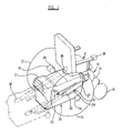
- FIGURE 1 shows a diagrammatic representation of the vehicle,
- FIGURE 2 illustrates a battery carrier, guide means and adjacent parts of the vehicle during engagement of the carrier with the guide means, the guide means being extended, and;
- FIGURE 3 illustrates the carrier and the guide means with the guide means retracted.
- The vehicle illustrated in the accompanying drawings comprises a
frame 10 on which there is mounted asingle seat 11 for a user of the vehicle. The seat may be demountable and provision may be made in a known manner for adjustment of the attitude and position of the seat with respect to the frame. Footrests also may be provided on the frame. The frame constitutes the body hereinbefore referred to. - The frame is supported from the ground by a number of wheels. In the example illustrated, there are four ground-engaging wheels identified by the
reference numbers 12 to 15. Thewheels electric motors wheels steerable wheels 14 and 15 a single steerable wheel, arranged in a known manner. - The
motors wheels motors wheels wheels - Power for driving the
motors battery 19 of electrical cells. The battery is contained in acarrier 20 which includes aremovable lid 21 and open-topped container 22. The cells may be arranged in two groups, each group of cells being in a respective case. - On the
container 22, there is provided afirst part 23 of a two-part electrical connector. The second part of this connector is mounted on theframe 10. Terminals of theconnector port 23 are connected by suitable leads with terminals of thebattery 19 and terminals of the connector parts 24 are connected by suitable leads in the electrical circuits of the vehicle, which include themotors connector 23, 24 necessarily connects the battery electrically with circuits of the vehicle. When the battery is moved substantially from the first position, theconnector parts 23 and 24 are separated so that the battery is automatically disconnected from the circuits of the vehicle, themotors - The
connector part 23 is mounted on asupport 25 which is mounted on thecontainer 22 with limited freedom for movement of the support relative to the container laterally and vertically. The connector part 24 is mounted on asimilar support 26 which, in turn, is mounted on theframe 10 for limited movement relative thereto laterally and vertically. Thesupports connector part 23 is moved towards the connector part 24 to establish alignment of the connector parts with each other. Typically, the locating formations comprise one or more pins on one of the supports and complementary sockets on the other support, either the pins or the sockets or both being tapered to accommodate the initial misalignment. It will be understood that one of thesupports container 22 may be achieved by the provision of pin and slot connections between these components. - The vehicle further comprises guide means for guiding the
battery 19 andcarrier 20 for movement relative to theframe 10 along a path which extends at right angles to the axis of the drivenwheels carrier 20 is moved from its first position illustrated in Figure 1 by full lines, it descends. When the carrier is in a second position at the limit of the travel provided by the guide means, the carrier is either at or is close to floor level. - The guide means comprises a pair of
telescopic slides frame 10. A further component of theslide 27 is rigidly secured to abracket 29 and the corresponding component of theslide 28 is rigidly secured to abracket 30. Thebattery carrier 20 has support means for co-operation with thebrackets rear pins carrier 20 at one side thereof for co-operation with thebracket 29 and corresponding pins (not shown) projecting from the opposite side of the carrier for co-operation with thebracket 30. Thebracket 29 has adjacent to its rear end an upwardly open slot for receiving therear pin 32. Towards the front of the bracket, there is a rearwardly open slot for receiving thepin 31. These pins project horizontally from the battery carrier and may bear rolling elements to reduce friction with the bracket. Thebracket 29 has a curved orinclined ramp 33 leading upwardly into the slot for receiving thepin 31. That part of the slot which is spaced from the ramp may be horizontal. Thebracket 30 is provided with corresponding slots for receiving the pins at the other side of the battery carrier. When the pins are seated in their respective slots, the bottom of the battery carrier is horizontal. - The
battery carrier 20 is provided with running means for running on the floor. Preferably, the running means comprises one or more rolling elements and the running means illustrated in the accompanying drawings comprises a pair ofwheels 34 mounted one adjacent to each of the front, lower corners of the battery carrier. Ahandle 35 is provided on the battery carrier at the end thereof remote from thewheels 34. - The
slides common handle 36 is provided for releasing these latches, thehandle 36 being connected with the latches by a suitable linkage. - When the battery 9 and
carrier 20 are in the first position, the centre of gravity of the battery lies somewhat below and slightly forwardly of the axis of rotation of the drivenwheels seat 11 and partly to the rear of the seat. The battery lies between the driven wheels and beneath themotors lid 21 from thecontainer 22 whilst the battery carrier is in the first position. - When the latches are released and the
slides battery 19 andcarrier 20 are moved relative to theframe 10 in a direction away from thesteerable wheels wheels seat 11. Although, when in the second position, thecarrier 20 may lie partly between the driven wheels, access to thelid 21 is not severely restricted and the lid can be removed. Access can be gained to the battery for checking of electrolyte level or for checking the connections with the terminals of the battery. - If better access is required to the battery or replacement of the battery is required, the
carrier 20 can readily be dismounted from theslides pin 32 out of its slot in thebracket 29. During such lifting of the rear end of the carrier, the carrier rocks on thefront pin 31 so that thewheels 34 move downwardly into firm engagement with the ground and partly support the weight of the battery and carrier. The carrier can then be drawn rearwardly from the remainder of the vehicle, thewheels 34 rolling on the floor. - When the
carrier 20 is to be returned to the vehicle, it is rolled on itswheels 34 up to the vehicle so that thepin 31 approaches theramp 33 and thepin 32 approaches the end of thebracket 29. The rear end of the carrier is then raised whilst thewheels 34 remain in contact with the floor. Accordingly, both thepin 31 and thepin 32 are raised. Thepin 32 is raised sufficiently to pass over the top of the bracket into its slot and thepin 31 is raised sufficiently to travel across theramp 33 into its slot. Once thepin 32 has been engaged in its slot, the carrier can be pushed forwardly to retract theslides - It will be noted that the length of the path of travel of the
carrier 20, whilst engaged with the guide means of the vehicle, is approximately equal to twice the length of the carrier. The vertical component of movement of the carrier along this path is considerably less than twice the length of the carrier and is preferably less than one third of the length of the path. The length of the path preferably exceeds the radius of the drivenwheels - It will be appreciated that the end of the vehicle at which the battery and carrier can be withdrawn is designated the rear of the vehicle because the
seat 11 faces away from that end of the vehicle. If the seat is mounted to face in the opposite direction, then the end of the vehicle at which the battery and carrier can be withdrawn would be designated the front of the vehicle. The vehicle may be arranged for withdrawal of the battery at either the front or the rear. In the particular example illustrated, the driven wheels are rear wheels but the driven wheels may alternatively be front wheels. Whilst we prefer to provide two motors for driving respective ones of the driven wheels, it would be within the scope of the invention to transmit drive from a single motor to both of the driven wheels, possibly through clutches or through a differential drive train. - The features disclosed in the foregoing description, or the following claims, or the accompanying drawings, expressed in their specific forms or in terms of a means for performing the disclosed function, or a method or process for attaining the disclosed result, as appropriate, may, separately or in any combination of such features, be utilised for realising the invention in diverse forms thereof.
Claims (11)
Priority Applications (1)
| Application Number | Priority Date | Filing Date | Title |
|---|---|---|---|
| AT89311887T ATE91403T1 (en) | 1988-11-16 | 1989-11-16 | VEHICLE AND METHOD OF LOCATING A BATTERY IN A VEHICLE. |
Applications Claiming Priority (2)
| Application Number | Priority Date | Filing Date | Title |
|---|---|---|---|
| GB8826769A GB2227463B (en) | 1988-11-16 | 1988-11-16 | Vehicle and method of installing an electrical battery in the vehicle |
| GB8826769 | 1988-11-16 |
Publications (2)
| Publication Number | Publication Date |
|---|---|
| EP0369792A1 true EP0369792A1 (en) | 1990-05-23 |
| EP0369792B1 EP0369792B1 (en) | 1993-07-14 |
Family
ID=10646930
Family Applications (1)
| Application Number | Title | Priority Date | Filing Date |
|---|---|---|---|
| EP89311887A Expired - Lifetime EP0369792B1 (en) | 1988-11-16 | 1989-11-16 | Vehicle and method of installing an electrical battery in the vehicle |
Country Status (7)
| Country | Link |
|---|---|
| EP (1) | EP0369792B1 (en) |
| AT (1) | ATE91403T1 (en) |
| AU (1) | AU4621289A (en) |
| CA (1) | CA2003041A1 (en) |
| DE (1) | DE68907564D1 (en) |
| GB (1) | GB2227463B (en) |
| WO (1) | WO1990005516A1 (en) |
Cited By (2)
| Publication number | Priority date | Publication date | Assignee | Title |
|---|---|---|---|---|
| WO1998047459A1 (en) * | 1997-04-18 | 1998-10-29 | Fundacion Once Para La Cooperacion E Integracion Social De Personas Con Minusvalias | Semi-automatic device for removing batteries from an electronic wheel-chair |
| WO2000058139A1 (en) * | 1999-03-25 | 2000-10-05 | Nanyang Technological University | Battery system and apparatus |
Families Citing this family (2)
| Publication number | Priority date | Publication date | Assignee | Title |
|---|---|---|---|---|
| FR2976540A1 (en) * | 2011-06-19 | 2012-12-21 | Yann Lavaud | Movable device i.e. terrestrial electric vehicle such as scooter, has battery block provided with pair of secondary fixing units, where secondary fixing units and primary fixing units are connected with each other |
| FR2998848B1 (en) * | 2012-12-04 | 2016-01-08 | Lavaud Innovations | MOBILE DEVICE PROVIDED WITH A REMOVABLE ELECTRIC POWER SOURCE SUCH AS A BATTERY |
Citations (4)
| Publication number | Priority date | Publication date | Assignee | Title |
|---|---|---|---|---|
| FR2272867A1 (en) * | 1974-05-27 | 1975-12-26 | Alpine Renault Automobiles | Electric vehicle battery replacement method - uses areas receiving run down batteries and holding charge overload batteries |
| FR2455886A1 (en) * | 1979-05-11 | 1980-12-05 | Freon Jean Francois | Electrically propelled wheelchair for handicapped person - has collapsible seat mounted on cantilever chassis with independent drive motors powering rear wheels |
| US4450400A (en) * | 1981-12-04 | 1984-05-22 | Gwyn Marion V | Battery replacement system for electric vehicles |
| FR2601241A1 (en) * | 1986-07-11 | 1988-01-15 | Girpeh Lorraine | Wheelchair for invalid or handicapped persons |
Family Cites Families (11)
| Publication number | Priority date | Publication date | Assignee | Title |
|---|---|---|---|---|
| US3688857A (en) * | 1970-08-17 | 1972-09-05 | Michael J Miller | Self-mounting power unit for wheel chairs |
| US3834563A (en) * | 1972-10-10 | 1974-09-10 | Ato Inc | Battery carrier |
| US3930552A (en) * | 1974-10-30 | 1976-01-06 | Fmc Corporation | Motor vehicle battery holder |
| US3989118A (en) * | 1975-10-16 | 1976-11-02 | Caterpillar Tractor Co. | Battery support with roll out frame |
| GB1598569A (en) * | 1977-04-22 | 1981-09-23 | Lucas Industries Ltd | Vehicles |
| GB2003436A (en) * | 1977-08-03 | 1979-03-14 | Rivaz R De | Electrically powered vehicle |
| FR2456658A1 (en) * | 1979-05-14 | 1980-12-12 | Bari Hugo | BICYCLE |
| DE2925393A1 (en) * | 1979-06-23 | 1981-01-08 | Deutsche Automobilgesellsch | MOTOR VEHICLE WITH A DEVICE FOR INSERTING AND DISPLACING AN ENERGY STORAGE |
| GB2085822B (en) * | 1980-10-13 | 1983-11-23 | Chloride Group Ltd | Battery cassette handler for a vehicle |
| DE3101557C2 (en) * | 1981-01-20 | 1982-10-21 | Jungheinrich Unternehmensverwaltung Kg, 2000 Hamburg | Lift truck |
| US4723618A (en) * | 1987-03-02 | 1988-02-09 | Deere & Company | Swing-out battery box |
-
1988
- 1988-11-16 GB GB8826769A patent/GB2227463B/en not_active Expired - Lifetime
-
1989
- 1989-11-15 CA CA002003041A patent/CA2003041A1/en not_active Abandoned
- 1989-11-16 DE DE8989311887T patent/DE68907564D1/en not_active Expired - Lifetime
- 1989-11-16 WO PCT/GB1989/001364 patent/WO1990005516A1/en not_active Ceased
- 1989-11-16 EP EP89311887A patent/EP0369792B1/en not_active Expired - Lifetime
- 1989-11-16 AT AT89311887T patent/ATE91403T1/en not_active IP Right Cessation
- 1989-11-16 AU AU46212/89A patent/AU4621289A/en not_active Abandoned
Patent Citations (4)
| Publication number | Priority date | Publication date | Assignee | Title |
|---|---|---|---|---|
| FR2272867A1 (en) * | 1974-05-27 | 1975-12-26 | Alpine Renault Automobiles | Electric vehicle battery replacement method - uses areas receiving run down batteries and holding charge overload batteries |
| FR2455886A1 (en) * | 1979-05-11 | 1980-12-05 | Freon Jean Francois | Electrically propelled wheelchair for handicapped person - has collapsible seat mounted on cantilever chassis with independent drive motors powering rear wheels |
| US4450400A (en) * | 1981-12-04 | 1984-05-22 | Gwyn Marion V | Battery replacement system for electric vehicles |
| FR2601241A1 (en) * | 1986-07-11 | 1988-01-15 | Girpeh Lorraine | Wheelchair for invalid or handicapped persons |
Cited By (2)
| Publication number | Priority date | Publication date | Assignee | Title |
|---|---|---|---|---|
| WO1998047459A1 (en) * | 1997-04-18 | 1998-10-29 | Fundacion Once Para La Cooperacion E Integracion Social De Personas Con Minusvalias | Semi-automatic device for removing batteries from an electronic wheel-chair |
| WO2000058139A1 (en) * | 1999-03-25 | 2000-10-05 | Nanyang Technological University | Battery system and apparatus |
Also Published As
| Publication number | Publication date |
|---|---|
| GB8826769D0 (en) | 1988-12-21 |
| ATE91403T1 (en) | 1993-07-15 |
| EP0369792B1 (en) | 1993-07-14 |
| CA2003041A1 (en) | 1990-05-16 |
| WO1990005516A1 (en) | 1990-05-31 |
| GB2227463B (en) | 1993-06-09 |
| AU4621289A (en) | 1990-06-12 |
| GB2227463A (en) | 1990-08-01 |
| DE68907564D1 (en) | 1993-08-19 |
Similar Documents
| Publication | Publication Date | Title |
|---|---|---|
| US4944359A (en) | Vehicle and method of releasably coupling parts of the vehicle together | |
| US9358895B2 (en) | Quick loading and unloading battery system for vehicles | |
| US5291959A (en) | Individual vehicle usable in a manual or a motorized version, in particular a wheelchair or a tricycle | |
| US5612606A (en) | Battery exchange system for electric vehicles | |
| US4102273A (en) | Apparatus for positioning battery-operated road vehicles at battery replacement stations | |
| US20220097967A1 (en) | Service vehicle | |
| EP0003888B1 (en) | Electrically driven vehicles | |
| US8347995B2 (en) | Automobile provided with a power supply battery which is removable by a vertical movement, and device for installing and removing such a battery | |
| RU2057041C1 (en) | Rail truck | |
| WO2023086130A1 (en) | Robotic vehicle | |
| EP0563892B1 (en) | Car and a device for inserting and taking out a wheel chair from a luggage compartment | |
| CN108394384B (en) | Mobility system, battery transport vehicle, electrically drivable motor vehicle and method of charging the drive battery of the motor vehicle | |
| US12017547B2 (en) | Vehicle having a cargo pod | |
| JP3529995B2 (en) | Vehicle battery exchange device | |
| EP0027638B1 (en) | A device for vertical and horizontal transport of loads into and out of a vehicle or the like | |
| GB2570870A (en) | An electric vehicle and a method of recharging an electric vehicle | |
| EP0369792A1 (en) | Vehicle and method of installing an electrical battery in the vehicle | |
| CN108383044A (en) | Lithium battery fork truck | |
| WO1993012945A1 (en) | An electric battery powered heavy vehicle | |
| CN208856853U (en) | Compact-sized fork truck | |
| EP1523970B1 (en) | Powered vehicle for personal mobility | |
| EP4292847A1 (en) | Travel vehicle | |
| CN210126588U (en) | Seat for small electric vehicle and small electric vehicle | |
| US3865266A (en) | Load carrier transfer | |
| US12594845B2 (en) | Traveling vehicle |
Legal Events
| Date | Code | Title | Description |
|---|---|---|---|
| PUAI | Public reference made under article 153(3) epc to a published international application that has entered the european phase |
Free format text: ORIGINAL CODE: 0009012 |
|
| AK | Designated contracting states |
Kind code of ref document: A1 Designated state(s): AT BE CH DE ES FR GB GR IT LI LU NL SE |
|
| RIN1 | Information on inventor provided before grant (corrected) |
Inventor name: GOULD, ROYSTON MERVYN |
|
| 17P | Request for examination filed |
Effective date: 19901102 |
|
| 17Q | First examination report despatched |
Effective date: 19920228 |
|
| GRAA | (expected) grant |
Free format text: ORIGINAL CODE: 0009210 |
|
| AK | Designated contracting states |
Kind code of ref document: B1 Designated state(s): AT BE CH DE ES FR GB GR IT LI LU NL SE |
|
| PG25 | Lapsed in a contracting state [announced via postgrant information from national office to epo] |
Ref country code: IT Free format text: LAPSE BECAUSE OF FAILURE TO SUBMIT A TRANSLATION OF THE DESCRIPTION OR TO PAY THE FEE WITHIN THE PRE;WARNING: LAPSES OF ITALIAN PATENTS WITH EFFECTIVE DATE BEFORE 2007 MAY HAVE OCCURRED AT ANY TIME BEFORE 2007. THE CORRECT EFFECTIVE DATE MAY BE DIFFERENT FROM THE ONE RECORDED.SCRIBED TIME-LIMIT Effective date: 19930714 Ref country code: SE Effective date: 19930714 Ref country code: DE Effective date: 19930714 Ref country code: AT Effective date: 19930714 Ref country code: ES Free format text: THE PATENT HAS BEEN ANNULLED BY A DECISION OF A NATIONAL AUTHORITY Effective date: 19930714 Ref country code: FR Effective date: 19930714 Ref country code: LI Effective date: 19930714 Ref country code: NL Effective date: 19930714 Ref country code: CH Effective date: 19930714 Ref country code: BE Effective date: 19930714 Ref country code: GR Free format text: LAPSE BECAUSE OF FAILURE TO SUBMIT A TRANSLATION OF THE DESCRIPTION OR TO PAY THE FEE WITHIN THE PRESCRIBED TIME-LIMIT Effective date: 19930714 |
|
| REF | Corresponds to: |
Ref document number: 91403 Country of ref document: AT Date of ref document: 19930715 Kind code of ref document: T |
|
| REF | Corresponds to: |
Ref document number: 68907564 Country of ref document: DE Date of ref document: 19930819 |
|
| REG | Reference to a national code |
Ref country code: CH Ref legal event code: PL |
|
| PG25 | Lapsed in a contracting state [announced via postgrant information from national office to epo] |
Ref country code: GB Effective date: 19931116 |
|
| PG25 | Lapsed in a contracting state [announced via postgrant information from national office to epo] |
Ref country code: LU Free format text: LAPSE BECAUSE OF NON-PAYMENT OF DUE FEES Effective date: 19931130 |
|
| EN | Fr: translation not filed | ||
| NLV1 | Nl: lapsed or annulled due to failure to fulfill the requirements of art. 29p and 29m of the patents act | ||
| PLBE | No opposition filed within time limit |
Free format text: ORIGINAL CODE: 0009261 |
|
| STAA | Information on the status of an ep patent application or granted ep patent |
Free format text: STATUS: NO OPPOSITION FILED WITHIN TIME LIMIT |
|
| 26N | No opposition filed | ||
| GBPC | Gb: european patent ceased through non-payment of renewal fee |
Effective date: 19931116 |