EP0369521A2 - Energy-absorbing construction element - Google Patents
Energy-absorbing construction element Download PDFInfo
- Publication number
- EP0369521A2 EP0369521A2 EP89202812A EP89202812A EP0369521A2 EP 0369521 A2 EP0369521 A2 EP 0369521A2 EP 89202812 A EP89202812 A EP 89202812A EP 89202812 A EP89202812 A EP 89202812A EP 0369521 A2 EP0369521 A2 EP 0369521A2
- Authority
- EP
- European Patent Office
- Prior art keywords
- metal rods
- installation part
- part according
- metal
- straight
- Prior art date
- Legal status (The legal status is an assumption and is not a legal conclusion. Google has not performed a legal analysis and makes no representation as to the accuracy of the status listed.)
- Granted
Links
Images


Classifications
-
- B—PERFORMING OPERATIONS; TRANSPORTING
- B62—LAND VEHICLES FOR TRAVELLING OTHERWISE THAN ON RAILS
- B62D—MOTOR VEHICLES; TRAILERS
- B62D1/00—Steering controls, i.e. means for initiating a change of direction of the vehicle
- B62D1/02—Steering controls, i.e. means for initiating a change of direction of the vehicle vehicle-mounted
- B62D1/04—Hand wheels
- B62D1/11—Hand wheels incorporating energy-absorbing arrangements, e.g. by being yieldable or collapsible
-
- F—MECHANICAL ENGINEERING; LIGHTING; HEATING; WEAPONS; BLASTING
- F16—ENGINEERING ELEMENTS AND UNITS; GENERAL MEASURES FOR PRODUCING AND MAINTAINING EFFECTIVE FUNCTIONING OF MACHINES OR INSTALLATIONS; THERMAL INSULATION IN GENERAL
- F16F—SPRINGS; SHOCK-ABSORBERS; MEANS FOR DAMPING VIBRATION
- F16F7/00—Vibration-dampers; Shock-absorbers
- F16F7/12—Vibration-dampers; Shock-absorbers using plastic deformation of members
Definitions
- the invention relates to a built-in part for absorbing energy, consisting of several, non-elastically deformable, straight metal rods arranged coaxially on a circle and fixed at their ends by a metal flange, in particular for integration in steering wheels of motor vehicles with respect to the plane of the steering wheel rim recessed steering wheel hub, with which the mounting part, which is covered on the handlebar side by an impact plate made of plastic that can be changed in shape, is firmly connected.
- components for absorbing energy which function on the principle of compressive change in shape of mechanical structures, are intended to absorb the force of the body of the driver of the motor vehicle against the steering wheel by means of deformation work in the event of collisions, i.e. the kinetic energy inherent in the driver is to be reduced over the longest possible routes and thus "small” forces, and in this way serious injuries to the driver are prevented.
- a steering wheel for motor vehicles is described in DE-B-1 912 528, whose part serving as the impact surface interacts in the event of an accident with a tubular installation part connected to the steering wheel hub for the absorption of energy.
- the built-in part has a lattice-shaped structure which is formed by a plurality of pairs of bands starting from a common point, which result in helical windings of the same pitch and opposite sense of pitch, the crossing points of the pairs of bands being evenly distributed over the circumference.
- an essential part of the deformation path goes through the pairs of bands and their Junction points are lost because they are stacked on top of each other under pressure load and thus reduce the deformation path.
- the tubular disadvantage described in DE-A-2 623 521 for absorbing energy also has the same disadvantage, with numerous systematically arranged openings, the wall sections which are effective in changing the shape being supposed to have approximately the same size.
- a built-in part for absorbing energy which consists of an elastically or plastically deformable metal body, which is formed from support elements arranged in a circle next to one another, such as webs, struts, rods or the like, and which at Pressure load on the steering wheel should result in an outward buckling of the support elements due to the arrangement of outwardly directed kink points.
- the disadvantage of such a built-in part is that too little energy is dissipated on the deformation path with sometimes dangerously high pressure force peaks. This disadvantage also applies to all of the above-mentioned tubular installation parts for absorbing energy.
- the object of the present invention is therefore to design the built-in part for absorbing energy in such a way that, in the event of a collision, the deformation force initially increases relatively steeply and then remains almost constant over the greatest length of the deformation path, so that the compression force path Characteristic curve results in a trapezoidal shape below the curve, which characterizes an installation part with ideal energy absorption capacity.
- the transverse dimensions of the prismatic metal bars are each small in relation to their longitudinal dimensions, the metal bars below the Influence of compressive force acting in the axial direction can be buckled in the direction of the larger main moment of inertia and in which a straight toothing extending transversely to the longitudinal direction is attached to at least one of the broad sides running perpendicular to the axis of the larger main moment of inertia and forming a right angle with the radius of the component.
- a built-in part designed in this way has an ideal energy absorption capacity under both static and dynamic pressure loads, since the characteristic curve for the dependence of the deformation force on the deformation path has an approximately trapezoidal shape in both pressure load cases.
- the buckling direction of the metal rods which takes place in the direction of their major principal moment of inertia, can be predetermined in that, according to a particular feature of the invention, the straight toothing is attached to the broad side opposite the desired buckling direction, preferably in the area of its free buckling length.
- An optimal energy absorption capacity can be achieved if the straight toothing of the metal rods is in the area of their free side on the broad side opposite the intended buckling direction Kink length and in the areas between their fastenings with the flanges and the turning points of the bend on the broad side pointing in the desired bend direction.
- the straight toothing of the metal bars extends over their broad sides.
- teeth connected in one piece with the comb are arranged in comb-like fashion on one or both of the narrow sides of the metal rods and bent out to form the straight toothing on the broad sides.
- a modification of this embodiment is to be seen in the fact that the comb-like tines are bent up to form the straight toothing so that they form a right angle with the broad side of the metal bars.
- the teeth of the straight toothing have an involute, cycloid, circular arc or U profile with vertical or inclined tooth flanks.
- FIG. 1 shows a schematic representation of a longitudinal section taken along the steering axis through a steering wheel connected to an installation part for absorbing energy
- FIG. 2 shows a side view of an installation part after the shape has changed.
- the built-in part (1) consists of several metal rods (2) made of steel of type St37, which are arranged coaxially on a circle and cannot be resiliently shaped, and which are firmly connected to one another at their ends by a steel flange (3, 4).
- the steering wheel spokes (6) connected to the steering wheel rim (5) are attached to the handlebar flange (3).
- the steering wheel hub (8) placed on the steering column (7) is fastened in the flange (4) on the steering column side.
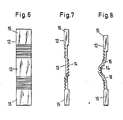
- the metal rod (12) shown in FIG. 6 as a side view in the direction of the axis of the major principal moment of inertia, which is shown in FIG. 7 as a side view perpendicular to the direction of the axis of the major principal moment of inertia, has in the area of the free buckling length (13) on the A straight toothing (14) with rectangular teeth is opposite the broadside on the opposite side.
- the straight toothing (14) runs on the one pointing in the buckling direction Broadside. 8 shows the metal rod (12) after the pressure has been applied.
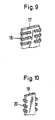
- Fig. 9 shows a perspective view of the section of a metal rod (17), in which the straight toothing is formed by tines (18) attached in comb-like manner on its two narrow sides and bent on one of the broad sides.
- Fig. 10 the portion of a metal rod (19) is shown in a perspective view, on the narrow sides of which comb-like teeth acting as straight teeth (20) are bent so that they form an angle of 90 ° with one of the broad sides.
- the deformation force is plotted over the deformation path, the dash-dotted line representing the deformation behavior of an ideal and the fully drawn curve representing the deformation behavior of the built-in part designed to absorb energy. It can be seen that the energy absorption capacity of the built-in part (1) designed according to the invention deviates comparatively slightly from the ideal course of the compressive force-displacement characteristic for a built-in part for absorbing energy.
Abstract
Description
Die Erfindung betrifft ein Einbauteil zur Absorption von Energie, bestehend aus mehreren auf einem Kreis koaxial angeordneten und an ihren Enden jeweils durch einen Metallflansch fest miteinander verbundenen, nicht-elastisch formänderbaren, geraden Metallstäben, insbesondere für die Integration in Lenkräder von Kraftfahrzeugen mit gegenüber der Ebene des Lenkradkranzes versenkter Lenkradnabe, mit der das lenkerseitig durch eine aus formänderbarem Kunststoff bestehende Aufprallplatte abgedeckte Einbauteil fest verbunden ist.The invention relates to a built-in part for absorbing energy, consisting of several, non-elastically deformable, straight metal rods arranged coaxially on a circle and fixed at their ends by a metal flange, in particular for integration in steering wheels of motor vehicles with respect to the plane of the steering wheel rim recessed steering wheel hub, with which the mounting part, which is covered on the handlebar side by an impact plate made of plastic that can be changed in shape, is firmly connected.
In Lenkanlagen für Kraftfahrzeuge eingebaute Bauteile zur Absorption von Energie, die nach dem Prinzip der stauchenden Formänderung von mechanischen Strukturen funktionieren, sollen bei Kollisionen die Wucht des gegen das Lenkrad geschleuderten Körpers des Lenkers des Kraftfahrzeugs durch Formänderungsarbeit aufnehmen, d.h. die dem Fahrer innenwohnende kinetische Energie soll über möglichst große Wege und damit "kleine" Kräfte abgebaut und auf diese Weise schwere Verletzungen des Fahrers verhindert werden.In steering systems for motor vehicles, components for absorbing energy, which function on the principle of compressive change in shape of mechanical structures, are intended to absorb the force of the body of the driver of the motor vehicle against the steering wheel by means of deformation work in the event of collisions, i.e. the kinetic energy inherent in the driver is to be reduced over the longest possible routes and thus "small" forces, and in this way serious injuries to the driver are prevented.
So ist in der DE-B-1 912 528 ein Lenkrad für Kraftfahrzeuge beschrieben, dessen als Aufprallfläche dienender Teil bei Unfällen mit einem mit der Lenkradnabe verbundenen rohrförmigen Einbauteil zur Absorption von Energie zusammenwirkt. Das Einbauteil besitzt eine gitterförmige Struktur, die durch mehrere von einem gemeinsamen Punkt ausgehende Bänderpaare, die schraubenförmige Wicklungen gleicher Steigung und entgegengesetzten Steigungssinnes ergeben, gebildet sind, wobei die Kreuzungsstellen der Bänderpaare gleichmäßig über den Umfang verteilt sind. Bei einem solchen Einbauteil geht ein wesentlicher Teil des Formänderungswegs durch die Bänderpaare und deren Kreuzungsstellen verloren, weil diese sich unter Drucklast zu einem Paket übereinander lagern und somit den Formänderungsweg reduzieren. Den gleichen Nachteil besitzt auch das in der DE-A-2 623 521 beschriebene rohrförmige Einbauteil zur Absorption von Energie mit zahlreichen systematisch angeordneten Durchbrüchen, wobei die bei der Formänderung wirksamen Wandungsabschnitte eine annähernd gleiche Größe besitzen sollen.For example, a steering wheel for motor vehicles is described in DE-B-1 912 528, whose part serving as the impact surface interacts in the event of an accident with a tubular installation part connected to the steering wheel hub for the absorption of energy. The built-in part has a lattice-shaped structure which is formed by a plurality of pairs of bands starting from a common point, which result in helical windings of the same pitch and opposite sense of pitch, the crossing points of the pairs of bands being evenly distributed over the circumference. With such an installation part, an essential part of the deformation path goes through the pairs of bands and their Junction points are lost because they are stacked on top of each other under pressure load and thus reduce the deformation path. The tubular disadvantage described in DE-A-2 623 521 for absorbing energy also has the same disadvantage, with numerous systematically arranged openings, the wall sections which are effective in changing the shape being supposed to have approximately the same size.
In der DE-A-2 614 041 ist ein Einbauteil zur Absorption von Energie vorgesehen, das aus einem elastisch oder plastisch verformbaren Metallkörper besteht, der aus im Kreis nebeneinander angeordneten Stützelementen, wie Stegen, Streben, Stäben oder dergleichen, gebildet ist und die bei Druckbelastung des Lenkrades durch die Anordnung von nach außen gerichteten Sollknickstellen ein Nachaußenknicken der Stützelemente bewirken sollen. Der Nachteil eines derartigen Einbauteils besteht darin, daß auf dem Formänderungsweg bei teilweise gefährlich hohen Druckkraftspitzen zu wenig Energie abgebaut wird. Dieser Nachteil gilt im übrigen auch für alle vorstehend angeführten rohrförmig gestalteten Einbauteile zur Absorption von Energie.In DE-A-2 614 041 a built-in part for absorbing energy is provided, which consists of an elastically or plastically deformable metal body, which is formed from support elements arranged in a circle next to one another, such as webs, struts, rods or the like, and which at Pressure load on the steering wheel should result in an outward buckling of the support elements due to the arrangement of outwardly directed kink points. The disadvantage of such a built-in part is that too little energy is dissipated on the deformation path with sometimes dangerously high pressure force peaks. This disadvantage also applies to all of the above-mentioned tubular installation parts for absorbing energy.
Aufgabe der vorliegenden Erfindung ist es deshalb, das eingangs beschriebene Einbauteil zur Absorption von Energie so zu gestalten, daß im Falle einer Kollision die Formänderungskraft anfangs verhältnismäßig steil ansteigt und dann über die weitaus größte Länge des Formänderungswegs nahezu konstant bleibt, so daß die Druckkraft-Weg-Kennlinie eine Trapezform unterhalb des Kurvenverlaufs ergibt, durch die ein Einbauteil mit idealem Energieabsorptionsvermögen charakterisiert ist.The object of the present invention is therefore to design the built-in part for absorbing energy in such a way that, in the event of a collision, the deformation force initially increases relatively steeply and then remains almost constant over the greatest length of the deformation path, so that the compression force path Characteristic curve results in a trapezoidal shape below the curve, which characterizes an installation part with ideal energy absorption capacity.
Gelöst ist diese Aufgabe dadurch, daß die Querabmessungen der prismatischen Metallstäbe jeweils klein im Verhältnis zu ihren Längsabmessungen sind, die Metallstäbe unter dem Einfluß von in axialer Richtung wirkender Druckkraft in Richtung des größeren Hauptträgheitsmoments ausknickbar sind und bei denen auf wenigstens einer der senkrecht zur Achse des größeren Hauptträgheitsmoments verlaufenden und einen rechten Winkel mit dem Radius des Bauteils bildenden Breitseiten eine quer zur Längsrichtung verlaufende Geradverzahnung angebracht ist.This object is achieved in that the transverse dimensions of the prismatic metal bars are each small in relation to their longitudinal dimensions, the metal bars below the Influence of compressive force acting in the axial direction can be buckled in the direction of the larger main moment of inertia and in which a straight toothing extending transversely to the longitudinal direction is attached to at least one of the broad sides running perpendicular to the axis of the larger main moment of inertia and forming a right angle with the radius of the component.
Ein derart ausgebildetes Einbauteil besitzt sowohl unter statischer als auch unter dynamischer Drucklast ein ideales Energieabsorptionsvermögen, da die Kennlinie für die Abhängigkeit der Formänderungskraft vom Formänderungsweg in beiden Drucklastfällen annähernd Trapezform aufweist.A built-in part designed in this way has an ideal energy absorption capacity under both static and dynamic pressure loads, since the characteristic curve for the dependence of the deformation force on the deformation path has an approximately trapezoidal shape in both pressure load cases.
Bei in axialer Richtung erfolgender stoßartiger Drucklast erfolgt ein Ausknicken der einzelnen Metallstäbe des Einbauteils mit kleinen sinusförmigen Ausbiegungen im Bereich ihrer freien Knicklänge, wobei die Formänderungskraft anfangs vergleichsweise steil ansteigt und über die größere Länge des Formänderungswegs konstant bleibt, da sich die Zähne der Geradverzahnung im Bereich der Ausknickung, beginnend in deren Maximum, fortschreitend gegeneinander abstützen.In the event of an impact-like pressure load in the axial direction, the individual metal rods of the insert part bend with small sinusoidal bends in the area of their free buckling length, the deformation force initially increasing comparatively steeply and remaining constant over the greater length of the deformation path, since the teeth of the straight toothing are in the area Support the buckling progressively against each other, starting at its maximum.
Die Ausknickrichtung der Metallstäbe, die jeweils in Richtung ihres größeren Hauptträgheitsmoments erfolgt, kann dadurch vorgegeben werden, daß gemäß einem besonderen Merkmal der Erfindung die Geradverzahnung auf der der angestrebten Ausknickrichtung gegenüberliegenden Breitseite, vorzugsweise im Bereich ihrer freien Knicklänge, angebracht ist.The buckling direction of the metal rods, which takes place in the direction of their major principal moment of inertia, can be predetermined in that, according to a particular feature of the invention, the straight toothing is attached to the broad side opposite the desired buckling direction, preferably in the area of its free buckling length.
Ein optimales Energieabsorptionsvermögen ist dann erreichbar, wenn die Geradverzahnung der Metallstäbe sowohl auf der der vorgesehenen Ausknickrichtung gegenüberliegenden Breitseite im Bereich ihrer freien Knicklänge und in den Bereichen zwischen ihren Befestigungen mit den Flanschen und den Wendepunkten der Ausknickung auf der in die gewünschte Ausknickrichtung weisenden Breitseite angebracht ist.An optimal energy absorption capacity can be achieved if the straight toothing of the metal rods is in the area of their free side on the broad side opposite the intended buckling direction Kink length and in the areas between their fastenings with the flanges and the turning points of the bend on the broad side pointing in the desired bend direction.
In aller Regel erstreckt sich die Geradverzahnung der Metallstäbe über deren Breitseiten.As a rule, the straight toothing of the metal bars extends over their broad sides.
Zur Erhöhung der Formänderungskraft der Metallstäbe besteht die Möglichkeit, eine von den parallel zu der die Achsen der beiden Hauptträgheitsmomente einschließenden Ebene liegenden Schmalseiten her angebrachte Geradverzahnung vorzusehen, die sich jeweils nur über weniger als 50 %, vorzugsweise 20 bis 40 %, der Breitseiten erstreckt.In order to increase the deformation force of the metal rods, there is the possibility of providing straight toothing, which extends from the narrow sides parallel to the plane including the axes of the two main moments of inertia, and which only extends over less than 50%, preferably 20 to 40%, of the broad sides.
Im Rahmen der vorzugsweisen Ausgestaltung der Erfindung sind an einer oder an beiden der Schmalseiten der Metallstäbe einteilig mit diesem verbundene Zinken kammartig angeordnet und unter Bildung der Geradverzahnung auf die Breitseiten aufgebogen.Within the scope of the preferred embodiment of the invention, teeth connected in one piece with the comb are arranged in comb-like fashion on one or both of the narrow sides of the metal rods and bent out to form the straight toothing on the broad sides.
Eine Abwandlung dieser Ausgestaltung ist darin zu sehen, daß die kammartig angebrachten Zinken zur Bildung der Geradverzahnung so hochgebogen sind, daß sie einen rechten Winkel mit der Breitseite der Metallstäbe bilden.A modification of this embodiment is to be seen in the fact that the comb-like tines are bent up to form the straight toothing so that they form a right angle with the broad side of the metal bars.
Als weitere Ausbildung der Metallstäbe besitzen die Zähne der Geradverzahnung ein Evolventen-, Zykloiden-, Kreisbogen- oder U-Profil mit senkrechten oder geneigten Zahnflanken.As a further development of the metal rods, the teeth of the straight toothing have an involute, cycloid, circular arc or U profile with vertical or inclined tooth flanks.
Das erfindungsgemäß gestaltete Einbauteil zur Absorption von Energie ist in den Zeichnungen beispielhaft dargestellt und wird nachfolgend näher erläutert.The built-in part according to the invention for absorbing energy is shown by way of example in the drawings and is explained in more detail below.
In Fig. 1 ist in schematischer Darstellung ein entlang der Lenkachse geführter Längsschnitt durch ein mit einem Einbauteil zur Absorption von Energie verbundenes Lenkrad und in Fig. 2 in einer Seitenansicht ein Einbauteil nach erfolgter Formänderung wiedergegeben. Das Einbauteil (1) besteht aus mehreren auf einem Kreis koaxial angeordneten, nicht-elastisch formänderbaren Metallstäben (2) aus Stahl des Typs St37, die an ihren Enden jeweils durch einen Stahlflansch (3,4) fest miteinander verbunden sind. An dem lenkerseitigen Flansch (3) sind die mit dem Lenkradkranz (5) verbundenen Lenkradspeichen (6) befestigt. Im lenksäulenseitigen Flansch (4) ist die auf die Lenksäule (7) aufgesetzte Lenkradnabe (8) befestigt.1 shows a schematic representation of a longitudinal section taken along the steering axis through a steering wheel connected to an installation part for absorbing energy, and FIG. 2 shows a side view of an installation part after the shape has changed. The built-in part (1) consists of several metal rods (2) made of steel of type St37, which are arranged coaxially on a circle and cannot be resiliently shaped, and which are firmly connected to one another at their ends by a steel flange (3, 4). The steering wheel spokes (6) connected to the steering wheel rim (5) are attached to the handlebar flange (3). The steering wheel hub (8) placed on the steering column (7) is fastened in the flange (4) on the steering column side.
Bei dem in Fig. 3 in einer Seitenansicht in Richtung der Achse des größeren Hauptträgheitsmoments dargestellten Metallstab (9), der in Fig. 4 in einer Seitenansicht senkrecht zur Richtung der Achse des größeren Hauptträgheitsmoments wiedergegeben ist, sind die beiden jeweils zur Achse des größeren Hauptträgheitsmoments senkrecht verlaufenden Breitseiten zwischen den mit den Flanschen zu verbindenden Befestigungen (10) mit einer Geradverzahnung (11) mit rechteckförmigen Zähnen versehen. Fig. 5 zeigt die Ausknickung des Metallstabs (9) nach erfolgter Druckbelastung.In the case of the metal rod (9) shown in a side view in FIG. 3 in the direction of the axis of the major principal moment of inertia, which is shown in FIG. 4 in a side view perpendicular to the direction of the axis of the major principal moment of inertia, the two are in each case to the axis of the major principal moment of inertia Provide vertical broad sides between the fastenings (10) to be connected to the flanges with straight teeth (11) with rectangular teeth. Fig. 5 shows the buckling of the metal rod (9) after the pressure has been applied.
Der in Fig. 6 als Seitenansicht in Richtung der Achse des größeren Hauptträgheitsmoments gezeigte Metallstab (12), der in Fig. 7 als Seitenansicht senkrecht zur Richtung der Achse des größeren Hauptträgheitsmoments dargestellt ist, besitzt im Bereich der freien Knicklänge (13) auf der der Ausknickrichtung gegenüberliegenden Breitseite eine Geradverzahnung (14) mit rechteckförmigen Zähnen. Im Bereich zwischen den mit den Flanschen zu verbindenden Befestigungen (15) des Metallstabs (12) und den Wendepunkten (16) der Ausknickung verläuft die Geradverzahnung (14) auf der in Ausknickrichtung weisenden Breitseite. In Fig. 8 ist der Metallstab (12) nach erfolgter Druckbelastung wiedergegeben.The metal rod (12) shown in FIG. 6 as a side view in the direction of the axis of the major principal moment of inertia, which is shown in FIG. 7 as a side view perpendicular to the direction of the axis of the major principal moment of inertia, has in the area of the free buckling length (13) on the A straight toothing (14) with rectangular teeth is opposite the broadside on the opposite side. In the area between the fastenings (15) of the metal rod (12) to be connected to the flanges and the turning points (16) of the buckling, the straight toothing (14) runs on the one pointing in the buckling direction Broadside. 8 shows the metal rod (12) after the pressure has been applied.
Fig. 9 zeigt in perspektivischer Darstellung das Teilstück eines Metallstabs (17), bei dem die Geradverzahnung durch an seinen beiden Schmalseiten kammartig angebrachte und auf eine der Breitseiten gebogene Zinken (18) gebildet ist.Fig. 9 shows a perspective view of the section of a metal rod (17), in which the straight toothing is formed by tines (18) attached in comb-like manner on its two narrow sides and bent on one of the broad sides.
In Fig. 10 ist in perspektivischer Darstellung das Teilstück eines Metallstabs (19) wiedergegeben, an dessen Schmalseiten kammartig angebrachte, als Geradverzahnung wirkende Zinken (20) so gebogen sind, daß sie mit einer der Breitseiten einen Winkel von 90° bilden.In Fig. 10, the portion of a metal rod (19) is shown in a perspective view, on the narrow sides of which comb-like teeth acting as straight teeth (20) are bent so that they form an angle of 90 ° with one of the broad sides.
Bei dem in Fig. 11 wiedergegebenen Druckkraft-Weg-Diagramm ist die Formänderungskraft über dem Formänderungsweg aufgetragen, wobei die strichpunktierte Linie das Formänderungsverhalten eines idealen und die voll ausgezogene Kurve das Formänderungsverhalten des erfindungsgemäß gestalteten Einbauteils zur Absorption von Energie wiedergibt. Es zeigt sich, daß das Energieabsorptionsvermögen des erfindungsgemäß gestalteten Einbauteils (1) vergleichsweise geringfügig von dem idealen Verlauf der Druckkraft-Weg-Kennlinie für ein Einbauteil zur Absorption von Energie abweicht.In the compressive force-displacement diagram shown in FIG. 11, the deformation force is plotted over the deformation path, the dash-dotted line representing the deformation behavior of an ideal and the fully drawn curve representing the deformation behavior of the built-in part designed to absorb energy. It can be seen that the energy absorption capacity of the built-in part (1) designed according to the invention deviates comparatively slightly from the ideal course of the compressive force-displacement characteristic for a built-in part for absorbing energy.
Claims (9)
Applications Claiming Priority (2)
| Application Number | Priority Date | Filing Date | Title |
|---|---|---|---|
| DE3838594 | 1988-11-15 | ||
| DE3838594A DE3838594A1 (en) | 1988-11-15 | 1988-11-15 | INSTALLATION COMPONENT FOR ABSORPTION OF ENERGY |
Publications (3)
| Publication Number | Publication Date |
|---|---|
| EP0369521A2 true EP0369521A2 (en) | 1990-05-23 |
| EP0369521A3 EP0369521A3 (en) | 1991-11-06 |
| EP0369521B1 EP0369521B1 (en) | 1995-02-22 |
Family
ID=6367163
Family Applications (1)
| Application Number | Title | Priority Date | Filing Date |
|---|---|---|---|
| EP89202812A Expired - Lifetime EP0369521B1 (en) | 1988-11-15 | 1989-11-08 | Energy-absorbing construction element |
Country Status (9)
| Country | Link |
|---|---|
| US (1) | US5005863A (en) |
| EP (1) | EP0369521B1 (en) |
| JP (1) | JPH02186140A (en) |
| BR (1) | BR8905785A (en) |
| DE (2) | DE3838594A1 (en) |
| ES (1) | ES2070170T3 (en) |
| MX (1) | MX172246B (en) |
| PT (1) | PT92310B (en) |
| TR (1) | TR24804A (en) |
Cited By (3)
| Publication number | Priority date | Publication date | Assignee | Title |
|---|---|---|---|---|
| WO1995023299A1 (en) * | 1994-02-25 | 1995-08-31 | Michel Malvy | Device for absorbing energy by plastic deformation for a motor vehicle steering wheel in particular, and steering wheel comprising such a device |
| EP0733514A1 (en) * | 1995-03-24 | 1996-09-25 | MST Automotive GmbH Automobil-Sicherheitstechnik | Safety steering wheel |
| FR3016202A1 (en) * | 2014-01-07 | 2015-07-10 | Autotech Engineering Aie | METAL BEAM WITH FLEXION ANGLE LIMIT |
Families Citing this family (16)
| Publication number | Priority date | Publication date | Assignee | Title |
|---|---|---|---|---|
| US5205186A (en) * | 1989-05-23 | 1993-04-27 | Eldra-Kunststofftechnik Gmbh | Steering wheel |
| US6268546B1 (en) | 1989-07-19 | 2001-07-31 | Calgene Llc | Ovary-tissue transcriptional factors |
| DE4105026C1 (en) * | 1991-02-19 | 1992-02-20 | Mercedes-Benz Aktiengesellschaft, 7000 Stuttgart, De | |
| JPH0575057U (en) * | 1992-03-13 | 1993-10-12 | 日本精工株式会社 | Shock absorption type steering column device |
| JPH07304457A (en) * | 1994-05-11 | 1995-11-21 | Toei Sangyo Kk | Steering wheel |
| GB2300606A (en) * | 1995-05-10 | 1996-11-13 | Dick Lucien Chitolie | A safety steering wheel |
| DE19729893C2 (en) * | 1997-07-12 | 1999-04-29 | Mc Micro Compact Car Ag | Steering column in a motor vehicle |
| DE19747873A1 (en) * | 1997-10-20 | 1999-04-22 | Petri Ag | Energy absorbing steering wheel |
| DE19747423C1 (en) * | 1997-10-27 | 1999-04-29 | Bsrs Restraint Syst Gmbh | Knee protector for passenger vehicle occupant |
| GB9817536D0 (en) * | 1998-08-13 | 1998-10-07 | Rover Group | A motor vehicle |
| US7188866B2 (en) * | 2004-02-26 | 2007-03-13 | Delphi Technologies, Inc | Steering column assembly and method of fabricating the same |
| DE202004003406U1 (en) | 2004-02-27 | 2004-05-13 | Takata-Petri Ag | Steering arrangement for motor vehicles |
| GB2426806A (en) * | 2005-04-27 | 2006-12-06 | Ford Global Tech Llc | A structural element designed to withstand a transverse load tending to bend the element |
| CN101157363A (en) * | 2006-10-07 | 2008-04-09 | 阎跃军 | Direction operation device |
| US20120048056A1 (en) * | 2010-08-31 | 2012-03-01 | Autoliv Asp, Inc. | Adaptive energy absorption steering wheel |
| JP7052310B2 (en) * | 2017-06-20 | 2022-04-12 | 日本精工株式会社 | Steering device and intermediate shaft |
Citations (3)
| Publication number | Priority date | Publication date | Assignee | Title |
|---|---|---|---|---|
| FR1586115A (en) * | 1968-07-02 | 1970-02-13 | ||
| DE2614041A1 (en) * | 1976-04-01 | 1977-10-06 | Petri Ag | ENERGY ABSORPTION ELEMENT |
| US4312430A (en) * | 1979-12-12 | 1982-01-26 | Izumi Motor Co., Ltd. | Shock absorber |
Family Cites Families (13)
| Publication number | Priority date | Publication date | Assignee | Title |
|---|---|---|---|---|
| US3373629A (en) * | 1966-04-29 | 1968-03-19 | Gen Motors Corp | Steering column assembly |
| US3495474A (en) * | 1966-11-24 | 1970-02-17 | Nissan Motor | Impact absorbing means for vehicles |
| FR1549902A (en) * | 1966-12-31 | 1968-12-13 | ||
| US3482466A (en) * | 1967-01-24 | 1969-12-09 | Helmut Orlich | Torsion device for steering columns |
| US3508633A (en) * | 1967-05-17 | 1970-04-28 | Nissan Motor | Plastically deformable impact absorbing means for vehicles |
| US3523587A (en) * | 1967-10-02 | 1970-08-11 | Ara Inc | Energy absorbing steering mechanism for vehicles |
| DE1912528B2 (en) * | 1969-03-12 | 1975-01-23 | Volkswagenwerk Ag, 3180 Wolfsburg | Safety steering wheel for motor vehicles |
| DE2042220B2 (en) * | 1970-08-26 | 1977-04-28 | Daimler-Benz Ag, 7000 Stuttgart | DEFORMABLE INSTRUMENT PANEL IN A MOTOR VEHICLE |
| DE2058411A1 (en) * | 1970-11-27 | 1972-06-08 | Daimler Benz Ag | Safety steering |
| GB1359760A (en) * | 1971-05-28 | 1974-07-10 | Daimler Benz Ag | Collapsible vehicle-steering column |
| DE3045141C2 (en) * | 1980-11-29 | 1987-07-09 | Messerschmitt-Bölkow-Blohm GmbH, 8000 München | Safety steering column for motor vehicles |
| DE3049425C2 (en) * | 1980-12-30 | 1991-09-05 | Messerschmitt-Bölkow-Blohm GmbH, 8000 München | Impact protection component |
| DE3321197C2 (en) * | 1983-06-11 | 1986-09-25 | Messerschmitt-Bölkow-Blohm GmbH, 8000 München | Tube, in particular for a safety steering column for motor vehicles |
-
1988
- 1988-11-15 DE DE3838594A patent/DE3838594A1/en not_active Withdrawn
-
1989
- 1989-11-08 DE DE58909030T patent/DE58909030D1/en not_active Expired - Lifetime
- 1989-11-08 EP EP89202812A patent/EP0369521B1/en not_active Expired - Lifetime
- 1989-11-08 ES ES89202812T patent/ES2070170T3/en not_active Expired - Lifetime
- 1989-11-13 JP JP1294766A patent/JPH02186140A/en active Pending
- 1989-11-13 US US07/436,275 patent/US5005863A/en not_active Expired - Fee Related
- 1989-11-14 BR BR898905785A patent/BR8905785A/en not_active Application Discontinuation
- 1989-11-14 PT PT92310A patent/PT92310B/en not_active IP Right Cessation
- 1989-11-15 TR TR89/0963A patent/TR24804A/en unknown
- 1989-11-15 MX MX018377A patent/MX172246B/en unknown
Patent Citations (3)
| Publication number | Priority date | Publication date | Assignee | Title |
|---|---|---|---|---|
| FR1586115A (en) * | 1968-07-02 | 1970-02-13 | ||
| DE2614041A1 (en) * | 1976-04-01 | 1977-10-06 | Petri Ag | ENERGY ABSORPTION ELEMENT |
| US4312430A (en) * | 1979-12-12 | 1982-01-26 | Izumi Motor Co., Ltd. | Shock absorber |
Cited By (7)
| Publication number | Priority date | Publication date | Assignee | Title |
|---|---|---|---|---|
| WO1995023299A1 (en) * | 1994-02-25 | 1995-08-31 | Michel Malvy | Device for absorbing energy by plastic deformation for a motor vehicle steering wheel in particular, and steering wheel comprising such a device |
| FR2716703A1 (en) * | 1994-02-25 | 1995-09-01 | Malvy Michel | Device for absorbing energy by plastic deformation, in particular for a vehicle steering wheel, and steering wheel equipped with such a device. |
| EP0733514A1 (en) * | 1995-03-24 | 1996-09-25 | MST Automotive GmbH Automobil-Sicherheitstechnik | Safety steering wheel |
| FR3016202A1 (en) * | 2014-01-07 | 2015-07-10 | Autotech Engineering Aie | METAL BEAM WITH FLEXION ANGLE LIMIT |
| WO2015104268A2 (en) | 2014-01-07 | 2015-07-16 | Autotech Engineering, A.I.E. | Metal beam with a limited bending angle |
| WO2015104268A3 (en) * | 2014-01-07 | 2015-09-03 | Autotech Engineering, A.I.E. | Metal beam with a limited bending angle |
| CN105899423A (en) * | 2014-01-07 | 2016-08-24 | 自动工程公司 | Metal beam with a limited bending angle |
Also Published As
| Publication number | Publication date |
|---|---|
| DE58909030D1 (en) | 1995-03-30 |
| PT92310A (en) | 1990-05-31 |
| PT92310B (en) | 1997-02-28 |
| DE3838594A1 (en) | 1990-05-17 |
| EP0369521B1 (en) | 1995-02-22 |
| EP0369521A3 (en) | 1991-11-06 |
| TR24804A (en) | 1992-03-26 |
| JPH02186140A (en) | 1990-07-20 |
| BR8905785A (en) | 1990-06-12 |
| MX172246B (en) | 1993-12-09 |
| US5005863A (en) | 1991-04-09 |
| ES2070170T3 (en) | 1995-06-01 |
Similar Documents
| Publication | Publication Date | Title |
|---|---|---|
| EP0369521B1 (en) | Energy-absorbing construction element | |
| EP0369520B1 (en) | Energy-absorption construction element | |
| DE602005004514T2 (en) | BUMPER ROD FOR ONE VEHICLE | |
| EP0266642B1 (en) | Plastic bumper | |
| DE3837190C1 (en) | ||
| DE2262293B2 (en) | Impact energy absorbing deformation element for motor vehicles, in particular passenger cars | |
| DE2751068C2 (en) | Shock-absorbing safety steering column for motor vehicles | |
| EP0602331B1 (en) | Motor vehicle with longitudinal beams deformable in a crash | |
| DE102013202607A1 (en) | Impact absorbing member | |
| DE2313588A1 (en) | FLOOR FRAME FOR MOTOR VEHICLES | |
| DE3426281A1 (en) | SHOCK ABSORBING WORM GEAR | |
| DE3617099C2 (en) | ||
| WO2001089909A1 (en) | Telescopic mechanism | |
| EP1090875A1 (en) | Telescopic crane boom | |
| DE2853244A1 (en) | BUMPER FOR MOTOR VEHICLES | |
| DE3007897C2 (en) | Load bars for vehicles, in particular for motor vehicles | |
| DE2900941C2 (en) | Bumpers for vehicles | |
| WO1992012358A1 (en) | Helical spring | |
| DE2318385A1 (en) | DEVICE FOR ABSORPTION OF ENERGY THROUGH PLASTIC DEFORMATION | |
| DE102021006094A1 (en) | Energy absorption device for an at least partially electrically operated motor vehicle | |
| EP0913599A2 (en) | Energy absorbing structure for vehicles | |
| DE2135872C2 (en) | Bumper fastening for automobiles | |
| DE4333891C2 (en) | Longitudinal guidance especially for motor vehicle seats | |
| DE102009041767B4 (en) | Connecting arrangement between a longitudinal member with a hollow profile and a body structure of a motor vehicle | |
| DE102006022503A1 (en) | Impact absorbing structure especially for vehicle has two elements with central crush zones bonded together to absorb impact in set direction |
Legal Events
| Date | Code | Title | Description |
|---|---|---|---|
| PUAI | Public reference made under article 153(3) epc to a published international application that has entered the european phase |
Free format text: ORIGINAL CODE: 0009012 |
|
| AK | Designated contracting states |
Kind code of ref document: A2 Designated state(s): DE ES FR GB IT SE |
|
| PUAL | Search report despatched |
Free format text: ORIGINAL CODE: 0009013 |
|
| AK | Designated contracting states |
Kind code of ref document: A3 Designated state(s): DE ES FR GB IT SE |
|
| 17P | Request for examination filed |
Effective date: 19911207 |
|
| 17Q | First examination report despatched |
Effective date: 19930730 |
|
| GRAA | (expected) grant |
Free format text: ORIGINAL CODE: 0009210 |
|
| AK | Designated contracting states |
Kind code of ref document: B1 Designated state(s): DE ES FR GB IT SE |
|
| ET | Fr: translation filed | ||
| REF | Corresponds to: |
Ref document number: 58909030 Country of ref document: DE Date of ref document: 19950330 |
|
| ITF | It: translation for a ep patent filed |
Owner name: STUDIO JAUMANN |
|
| REG | Reference to a national code |
Ref country code: ES Ref legal event code: FG2A Ref document number: 2070170 Country of ref document: ES Kind code of ref document: T3 |
|
| GBT | Gb: translation of ep patent filed (gb section 77(6)(a)/1977) |
Effective date: 19950518 |
|
| PGFP | Annual fee paid to national office [announced via postgrant information from national office to epo] |
Ref country code: SE Payment date: 19950906 Year of fee payment: 7 |
|
| PGFP | Annual fee paid to national office [announced via postgrant information from national office to epo] |
Ref country code: FR Payment date: 19950915 Year of fee payment: 7 |
|
| PGFP | Annual fee paid to national office [announced via postgrant information from national office to epo] |
Ref country code: GB Payment date: 19951026 Year of fee payment: 7 |
|
| PGFP | Annual fee paid to national office [announced via postgrant information from national office to epo] |
Ref country code: ES Payment date: 19951130 Year of fee payment: 7 |
|
| PGFP | Annual fee paid to national office [announced via postgrant information from national office to epo] |
Ref country code: DE Payment date: 19951221 Year of fee payment: 7 |
|
| PLBE | No opposition filed within time limit |
Free format text: ORIGINAL CODE: 0009261 |
|
| STAA | Information on the status of an ep patent application or granted ep patent |
Free format text: STATUS: NO OPPOSITION FILED WITHIN TIME LIMIT |
|
| 26N | No opposition filed | ||
| PG25 | Lapsed in a contracting state [announced via postgrant information from national office to epo] |
Ref country code: DE Effective date: 19960702 |
|
| PG25 | Lapsed in a contracting state [announced via postgrant information from national office to epo] |
Ref country code: GB Effective date: 19961108 |
|
| PG25 | Lapsed in a contracting state [announced via postgrant information from national office to epo] |
Ref country code: SE Effective date: 19961109 Ref country code: ES Free format text: LAPSE BECAUSE OF NON-PAYMENT OF DUE FEES Effective date: 19961109 |
|
| GBPC | Gb: european patent ceased through non-payment of renewal fee |
Effective date: 19961108 |
|
| PG25 | Lapsed in a contracting state [announced via postgrant information from national office to epo] |
Ref country code: FR Effective date: 19970731 |
|
| EUG | Se: european patent has lapsed |
Ref document number: 89202812.7 |
|
| REG | Reference to a national code |
Ref country code: FR Ref legal event code: ST |
|
| REG | Reference to a national code |
Ref country code: ES Ref legal event code: FD2A Effective date: 19971213 |
|
| PG25 | Lapsed in a contracting state [announced via postgrant information from national office to epo] |
Ref country code: IT Free format text: LAPSE BECAUSE OF NON-PAYMENT OF DUE FEES;WARNING: LAPSES OF ITALIAN PATENTS WITH EFFECTIVE DATE BEFORE 2007 MAY HAVE OCCURRED AT ANY TIME BEFORE 2007. THE CORRECT EFFECTIVE DATE MAY BE DIFFERENT FROM THE ONE RECORDED. Effective date: 20051108 |