EP0369501A1 - Taping unit for cardboard case taping machines with an improved movement for the return of the entry application roller - Google Patents
Taping unit for cardboard case taping machines with an improved movement for the return of the entry application roller Download PDFInfo
- Publication number
- EP0369501A1 EP0369501A1 EP89202579A EP89202579A EP0369501A1 EP 0369501 A1 EP0369501 A1 EP 0369501A1 EP 89202579 A EP89202579 A EP 89202579A EP 89202579 A EP89202579 A EP 89202579A EP 0369501 A1 EP0369501 A1 EP 0369501A1
- Authority
- EP
- European Patent Office
- Prior art keywords
- entry
- roller
- frame
- taping unit
- case
- Prior art date
- Legal status (The legal status is an assumption and is not a legal conclusion. Google has not performed a legal analysis and makes no representation as to the accuracy of the status listed.)
- Granted
Links
Images


Classifications
-
- B—PERFORMING OPERATIONS; TRANSPORTING
- B65—CONVEYING; PACKING; STORING; HANDLING THIN OR FILAMENTARY MATERIAL
- B65B—MACHINES, APPARATUS OR DEVICES FOR, OR METHODS OF, PACKAGING ARTICLES OR MATERIALS; UNPACKING
- B65B51/00—Devices for, or methods of, sealing or securing package folds or closures; Devices for gathering or twisting wrappers, or necks of bags
- B65B51/04—Applying separate sealing or securing members, e.g. clips
- B65B51/06—Applying adhesive tape
- B65B51/067—Applying adhesive tape to the closure flaps of boxes
-
- Y—GENERAL TAGGING OF NEW TECHNOLOGICAL DEVELOPMENTS; GENERAL TAGGING OF CROSS-SECTIONAL TECHNOLOGIES SPANNING OVER SEVERAL SECTIONS OF THE IPC; TECHNICAL SUBJECTS COVERED BY FORMER USPC CROSS-REFERENCE ART COLLECTIONS [XRACs] AND DIGESTS
- Y10—TECHNICAL SUBJECTS COVERED BY FORMER USPC
- Y10T—TECHNICAL SUBJECTS COVERED BY FORMER US CLASSIFICATION
- Y10T156/00—Adhesive bonding and miscellaneous chemical manufacture
- Y10T156/12—Surface bonding means and/or assembly means with cutting, punching, piercing, severing or tearing
- Y10T156/1317—Means feeding plural workpieces to be joined
- Y10T156/1343—Cutting indefinite length web after assembly with discrete article
Definitions
- the present invention relates to a taping unit for cardboard case taping machines with an improved movement for the return of the entry application roller.
- tape unit relates to those automatic machines which execute the application of lengths of adhesive tape on the top and bottom walls (and in part on the leading and trailing vertical ones) of parellelepiped cardboard cases which are made to progress along a predetermined operating path.
- the (taping units) are the particular mechanisms (usually two per machine, one lower and one upper) used for the delivery of the tape and for its adhesion to the case walls.
- Known taping units comprise essentially a support frame to be inserted in a suitable space of the taping machine, delivery means for the adhesive tape, an entry application roller for the application of the tape on a short vertical part of the leading wall of the case and along the entire bottom or top wall (according as to whether the taping unit is fitted to the bottom or to the top) of the case, an exit application roller for the application of the tape on a short vertical part of the trailing wall of the case and a cutting blade for the separation of the desired length of tape from a continuous roll which may be used for several operations.
- the two application rollers move between an extracted or at rest position in which they protrude from the outline of the frame of the taping unit so that they are inserted in the progress path of the case and a retracted position in which the rollers are included completely within the outline of the frame so as to allow the progress of the case itself.
- the displacement of the entry application roller from the extracted position to the retracted position is determined by the engagement of the leading wall of the case with the roller itself, which is forced by the above leading wall to move progressively along a retracted path which will allow it to simultaneously apply the adhesive tape to the leading wall of the case. Once retracted, and while the case continues to progress the same entry roller then continues the application of the tape along the bottom or top wall of the case.
- the similar movement of the exit application roller can in turn be controlled autonomously, but still by the engagement with the progressing case, and it may also be the direct and compulsory consequence of the retraction movement of the entry roller.
- the return movement of the two application rollers to the extracted position is subsequently determined by the disengagement of the case from the rollers themselves in combination with the pushing action suitable elastic means. During such return movement the exit roller makes the tape adhere to the trailing wall of the case.
- the return movement of the entry application roller which must occur so as to ensure the correct application of the tape to the leading wall of the case with a suitable passage over the critical point represented by the jointing edge between the above leading wall and the adjacent bottom or top wall, where there are also present the ends of the folded side flaps which ensure the closing of the case and where it is possible that the above ends be turned over.
- the return movement of the entry roller must be such as not to damage the case, in particular again at the above edge. In other words, the movement must be executed so that the tape is forced sufficiently firmly against the case but also so as to avoid resistances greater than those which the case itself may sustain.
- a known system for the return of the entry roller provides for the roller to be freely supported in a rotatable way by an arm pivoted on a fixed axis included within the outline of the frame of the taping unit and next to the latter's entry end, so that the roller follows a path of an arc of a circle which is convex towards the outside.
- Another known system invented so as to overcome the above disadvantage has the entry application roller mounted on a support arm which is movable along an oblique rectilinear guide so as to follow a rectilinear path with component in the direction of the progress of the case.
- This solves the problems related to the resistance and to the entry angle, but makes it inevitable to use a frame of larger dimensions, so as to accommodate the long stroke of the roller retraction.
- the problem is created of accompanying and recovering the tape when the roller performs the roller retraction movement.
- the object of the present invention is to accomplish a taping unit with a retraction system of the entry application roller which overcomes the disadvantages of the abovementioned known systems, allowing a suitable limitation of the forces required and of the entry angle without, however, having to increase the size of the outline of the taping unit and at the same time creating problems in relation to accompanying and recovering the tape.
- a taping unit of the type comprising a supporting frame, delivery means for the adhesive tape, an entry application roller and an exit application roller which can be moved between an extracted or at rest position in which they protrude from the outline of the frame of the taping unit so that they are inserted in the progress path of the case and a retracted position in which they are included completely within the outline of the frame so as to allow the progress of the case itself, and cutting means for the separation of the desired length of tape to be applied to the progressing case, characterized in that said entry application roller is mounted on a movable support engaged with guiding means contained within the outline of said frame and conformed so as to move said entry roller along a circular path with its centre outside said frame.
- the guide means be selected so as to determine a circular path with its centre upstream from the entry end of the taping unit and displaced in a direction opposite to that in which the entry roller protrudes with respect to the surface on which the case is placed on the taping unit frame.
- Such circular path is thus convex towards the outside of the unit, as described in the known art described above.
- a second, more innovative, possibility is that the guide means be selected instead so as to determine a circular path with its centre downstream from the entry end of the taping unit and displaced in a direction which is the same as that in which the entry roller protrudes with respect to the plane where the case is placed on the taping unit frame.
- a circular path is thus obtained which is convex towards the inside of the unit, that is which is concave towards the outside of the unit itself.
- the guide means used to determine the desired movement with circular path of the entry roller.
- Those currently preferred derive from the previous Italian patent No. 1176999 in the name of the same Applicant and consist of a fixed pivot slidably engaged in a suitably shaped slot of the entry roller's mobile support and in a connecting pivot between the same mobile support and an arm rotating on a fixed axis included within the outline of the taping unit's frame and next to the exit end of the frame itself.
- the inlet roller support, and therefore the inlet roller itself may be made to move along any path which depends on the shape of the guide slot and, with an appropriate selection of the latter, may indeed become circular with its centre outside the frame as achieved by the present invention.
- Fig.s 1 and 2 show a taping unit according to the invention, suitable for the application of adhesive tape along the bottom wall and along part of the leading and trailing walls of parellelepiped cardboard cases which is made to progress from right to left according to the arrows A shown in the above figures.
- the same taping unit turned upside down will however be utilized for the application of adhesive tape along the top wall and along part of the leading and trailing walls of the same or a similar case.
- the taping unit of Fig.s 1 and 2 is essentially of the type described in the Italian patent No. 1176999 in the name of the same Applicant, whose description is herein incorporated for any minor details, and comprises a support frame 1 formed according to the known art by parallel vertical sides 2 rigidly connected together. From the frame 1 an arm 3 extends downwards for the support and withdrawal of an adhesive tape 4 from a conventional roll (not shown) which may be used for several taping operations.
- the frame 1 supports the taping members and the appropriate driving mechanisms.
- a first taping member is constituted by an entry application roller 5, which is supported in a freely rotatable way by a mobile support 6 formed by a pair of parallel shoulders 7 rigidly constrained together.
- the two shoulders 7 have identical shaped slots 8, in which a fixed pivot 9 is slidably engaged.
- a connecting pivot 10 also achieves a pivoting constraint between the two shoulders 7 and one end of a T-arm 11 with central stem rotatable on a fixed pivot 12.
- a second taping member is constituted by an exit application roller 13, which is supported in a freely rotatable way by another mobile support 14 formed by a pair of parallel levers 15 rigidly constrained together.
- the two levers 15 are pivoted on a fixed pivot 16 and held in the at rest position of Fig. 1 by a helical spring 17, of which one end is attached to an end pin 18 of the levers 15 and the other end is attached to the corresponding end of a chain 19 connected at 20 to an adjustment mechanism 21, which by means of the position of chain 20 adjusts the tension of the spring 17.
- the two levers also have equal transverse slots 22, in which a pin 23 is slidably engaged supported by the other end of the T-arm 11. Between the two levers 15 there is positioned and fixed a small trapezoidal-shaped block 42, whose purposes will be explained later.
- a cutting blade 24 supported, in an intermediate position between the two application rollers 5 and 13, by a pair of levers 25, which have a drive portion 26 and are pivoted at 27 on a second pair of levers 28 pivoted on a fixed pivot 29 and equipped with a drive portion 30.
- a wire spring 31 acts, which at one end is fastened at 32 to the levers 25 and goes on to another end fastened to an adjustable retainer 33, further passing over intermediate elements 34 and 35, of which the first of fixed and other is supported by the levers 25.
- the above delivery means comprise an intermediate roller 36 rotatably supported by the pair of levers 28, an intermediate roller 37 rotatably supported by the frame 1 and an intermediate roller 38 rotatably supported by the mobile support 6.
- the extracted position is also manintained for the entry application roller 5, on whose cylindrical wall the free end of the adhesive tape 4 has been previously positioned according to the known art.
- the spring 31 in turn keeps the two pairs of levers 25 and 28 in the position illustrated in Fig. 1, with the respective driving portions 26 and 30 outside the outline of the frame 1 and in the progress path of the case 51.
- the cutting blade 24 is thus within the outline of the frame 1, protected by the cover elements 39 and 40, the second of which is traversed by a slot 41 for the passage of the blade 24 during the tape cutting operation.
- the initial engagement of the leading wall 52 of the arriving case determines in the first place the adhesion of the free end of the adhesive tape 4 to the same leading wall, after which the progress of the case in the direction of the arrow A determines a progressive retraction movement of the entry application roller 5 within the outline of the frame 1 so as to permit the case's subsequent progress.
- the exit application roller 13 there is the retraction of the exit application roller 13.
- the spring 31 determines the sharp clockwise rotation of the levers 28 and, due to the engagement of the driving portion 26 with the bottom wall of the case, there is a simultaneous sharp anti-clockwise rotation of the levers 25, so that the cutting blade 24 moves sharply through the slot 41 and against the adhesive tape, and the tape is cut.
- the retraction movement of the entry roller 5, previously described, is guided by the engagement of the fixed pivot 9 in the shaped slots 8 of the mobile support 6 in combination with the pivoted connection achieved by the pivot 10 between the support 6 and the rotating T-arm 11.
- the path followed by the entry roller 5 is essentially determined by the shape of the slots 8 and in the case of the taping unit shown in Fig.s 1 and 2 is that represented in Fig. 2, that is, an arc of a circle 43 with centre C on the outside of the frame 1, upstream from the latter's entry end and below the surface on which the case 1 is placed on the frame 1.
- the path in the shape of a circular arc of the entry roller has a large radius of curvature R and is convex upwards and is selected so as to ensure a large lever arm with a small entry angle of the roller, while the outline of the taping unit is not increased as a result of the position of the centre C.
- the slots 8 may be shaped as shown in Fig. 5, thus determining a path 43 which is still circular with a large radius R but whose centre C is above the surface on which the case is placed and downstream from the entry end of the frame 1 (Fig. 6).
- This solution has the merit that it determines a very small entry angle of the roller and thus a very smooth passage over the edge 54 of the case with consequent reduction in the danger of overturning the leading ends of the closing side flaps of the case's bottom.
- the slots 8 may have a terminal portion 44 facing upwards (Fig. 7) with a consequent essentially vertical section 45 of the circular path 43 (Fig. 8).
Abstract
Description
- The present invention relates to a taping unit for cardboard case taping machines with an improved movement for the return of the entry application roller.
- The term (taping unit) relates to those automatic machines which execute the application of lengths of adhesive tape on the top and bottom walls (and in part on the leading and trailing vertical ones) of parellelepiped cardboard cases which are made to progress along a predetermined operating path.
- In such machines the (taping units) are the particular mechanisms (usually two per machine, one lower and one upper) used for the delivery of the tape and for its adhesion to the case walls.
- Known taping units comprise essentially a support frame to be inserted in a suitable space of the taping machine, delivery means for the adhesive tape, an entry application roller for the application of the tape on a short vertical part of the leading wall of the case and along the entire bottom or top wall (according as to whether the taping unit is fitted to the bottom or to the top) of the case, an exit application roller for the application of the tape on a short vertical part of the trailing wall of the case and a cutting blade for the separation of the desired length of tape from a continuous roll which may be used for several operations.
- The two application rollers move between an extracted or at rest position in which they protrude from the outline of the frame of the taping unit so that they are inserted in the progress path of the case and a retracted position in which the rollers are included completely within the outline of the frame so as to allow the progress of the case itself.
- The displacement of the entry application roller from the extracted position to the retracted position is determined by the engagement of the leading wall of the case with the roller itself, which is forced by the above leading wall to move progressively along a retracted path which will allow it to simultaneously apply the adhesive tape to the leading wall of the case. Once retracted, and while the case continues to progress the same entry roller then continues the application of the tape along the bottom or top wall of the case.
- The similar movement of the exit application roller can in turn be controlled autonomously, but still by the engagement with the progressing case, and it may also be the direct and compulsory consequence of the retraction movement of the entry roller.
- The return movement of the two application rollers to the extracted position is subsequently determined by the disengagement of the case from the rollers themselves in combination with the pushing action suitable elastic means. During such return movement the exit roller makes the tape adhere to the trailing wall of the case.
- Of particular interest is the return movement of the entry application roller, which must occur so as to ensure the correct application of the tape to the leading wall of the case with a suitable passage over the critical point represented by the jointing edge between the above leading wall and the adjacent bottom or top wall, where there are also present the ends of the folded side flaps which ensure the closing of the case and where it is possible that the above ends be turned over. At the same time the return movement of the entry roller must be such as not to damage the case, in particular again at the above edge. In other words, the movement must be executed so that the tape is forced sufficiently firmly against the case but also so as to avoid resistances greater than those which the case itself may sustain.
- A known system for the return of the entry roller provides for the roller to be freely supported in a rotatable way by an arm pivoted on a fixed axis included within the outline of the frame of the taping unit and next to the latter's entry end, so that the roller follows a path of an arc of a circle which is convex towards the outside.
- This known system has the disadvantage that, so as not to substantially increase the size of the taping unit, the entry roller support arm is necessarily somewhat short and determines an entry angle of the roller within the outline of the frame which is fairly substantial. This causes an undesirable resistance at the most delicate point of the case, that is at the abovementioned jointing edge between the leading wall and either the bottom or the top wall.
- Another known system invented so as to overcome the above disadvantage has the entry application roller mounted on a support arm which is movable along an oblique rectilinear guide so as to follow a rectilinear path with component in the direction of the progress of the case. This solves the problems related to the resistance and to the entry angle, but makes it inevitable to use a frame of larger dimensions, so as to accommodate the long stroke of the roller retraction. In addition, again as a result of the length of the retraction stroke, the problem is created of accompanying and recovering the tape when the roller performs the roller retraction movement.
- In view of this state of the art, the object of the present invention is to accomplish a taping unit with a retraction system of the entry application roller which overcomes the disadvantages of the abovementioned known systems, allowing a suitable limitation of the forces required and of the entry angle without, however, having to increase the size of the outline of the taping unit and at the same time creating problems in relation to accompanying and recovering the tape.
- According to the invention such object is achieved with a taping unit of the type comprising a supporting frame, delivery means for the adhesive tape, an entry application roller and an exit application roller which can be moved between an extracted or at rest position in which they protrude from the outline of the frame of the taping unit so that they are inserted in the progress path of the case and a retracted position in which they are included completely within the outline of the frame so as to allow the progress of the case itself, and cutting means for the separation of the desired length of tape to be applied to the progressing case, characterized in that said entry application roller is mounted on a movable support engaged with guiding means contained within the outline of said frame and conformed so as to move said entry roller along a circular path with its centre outside said frame.
- In this way, without changing the usual outline of the taping unit, it is possible to impart a wide-radius circular movement to the entry roller whereby it is possible to reduce the forces required and to have the most suitable entry angle. Any possible damage to the box is thus avoided and the passage over the critical edge between the leading wall and either the bottom or the top wall of the case is avoided. By suitably selecting the amplitude and the curvature of the retraction path, it is on the other hand possible to avoid the occurrence of problems related to the accompaniment and recovery of the tape.
- A first possibility is that the guide means be selected so as to determine a circular path with its centre upstream from the entry end of the taping unit and displaced in a direction opposite to that in which the entry roller protrudes with respect to the surface on which the case is placed on the taping unit frame. Such circular path is thus convex towards the outside of the unit, as described in the known art described above.
- A second, more innovative, possibility is that the guide means be selected instead so as to determine a circular path with its centre downstream from the entry end of the taping unit and displaced in a direction which is the same as that in which the entry roller protrudes with respect to the plane where the case is placed on the taping unit frame. A circular path is thus obtained which is convex towards the inside of the unit, that is which is concave towards the outside of the unit itself. The situation is thus inverted with respect to the known art and permits the achievement of a much reduced entry angle and such as to obtain a smooth passage over the cases's edge, so that the drawback is appreciably reduced of turning over the side flaps of the bottom or top of the case at the moment of the passage over the jointing edge between the leading wall and either the bottom or the top of the case itself.
- In both cases, a further possible improvement is achievable by conforming the guide means so that the circular path determined by them ends with its last section at a greater vertical angle. In this way it is possible for the entry roller to pass more rapidly over the case's edge, while it does not create any problem of forces because the entry roller at that point has already engaged the bottom or the top wall of the case.
- Many and of various types may be the guide means used to determine the desired movement with circular path of the entry roller. Those currently preferred derive from the previous Italian patent No. 1176999 in the name of the same Applicant and consist of a fixed pivot slidably engaged in a suitably shaped slot of the entry roller's mobile support and in a connecting pivot between the same mobile support and an arm rotating on a fixed axis included within the outline of the taping unit's frame and next to the exit end of the frame itself. With this guide system the inlet roller support, and therefore the inlet roller itself, may be made to move along any path which depends on the shape of the guide slot and, with an appropriate selection of the latter, may indeed become circular with its centre outside the frame as achieved by the present invention.
- Examples of the use of such guide means to determine the path of the entry roller according to the present invention are illustrated for purposes of demonstration but not as a limitation, in the enclosed drawings, in which:
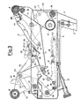
- Fig. 1 is a longitudinal section of the taping unit according to the invention with the entry and exit application rollers in the extracted or at rest position;
- Fig. 2 shows the same taping unit illustrated in Fig. 1 with the application rollers in the retracted position;
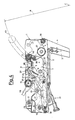
- Fig. 3 shows another taping unit according to the invention with the application rollers in the extracted or at rest position;
- Fig. 4 shows the same taping unit illustrated in Fig. 3 with the application rollers in the retracted position;
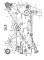
- Fig. 5 shows yet another taping unit according to the invention with the application rollers in the extracted or at rest position;
- Fig. 6 shows the same taping unit illustrated in Fig. 5 with the application rollers in the retracted position;
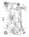
- Fig. 7 shows another taping unit according to the invention with the application rollers in the extracted or at rest position;
- Fig. 8 shows the same taping unit illustrated in Fig. 7 with the application rollers in the retracted position.
- Fig.s 1 and 2 show a taping unit according to the invention, suitable for the application of adhesive tape along the bottom wall and along part of the leading and trailing walls of parellelepiped cardboard cases which is made to progress from right to left according to the arrows A shown in the above figures. The same taping unit turned upside down will however be utilized for the application of adhesive tape along the top wall and along part of the leading and trailing walls of the same or a similar case.
- The taping unit of Fig.s 1 and 2 is essentially of the type described in the Italian patent No. 1176999 in the name of the same Applicant, whose description is herein incorporated for any minor details, and comprises a
support frame 1 formed according to the known art by parallelvertical sides 2 rigidly connected together. From theframe 1 anarm 3 extends downwards for the support and withdrawal of anadhesive tape 4 from a conventional roll (not shown) which may be used for several taping operations. - The
frame 1 supports the taping members and the appropriate driving mechanisms. - A first taping member is constituted by an
entry application roller 5, which is supported in a freely rotatable way by amobile support 6 formed by a pair ofparallel shoulders 7 rigidly constrained together. The twoshoulders 7 have identicalshaped slots 8, in which a fixedpivot 9 is slidably engaged. A connectingpivot 10 also achieves a pivoting constraint between the twoshoulders 7 and one end of a T-arm 11 with central stem rotatable on a fixedpivot 12. - A second taping member is constituted by an
exit application roller 13, which is supported in a freely rotatable way by anothermobile support 14 formed by a pair ofparallel levers 15 rigidly constrained together. The twolevers 15 are pivoted on a fixedpivot 16 and held in the at rest position of Fig. 1 by ahelical spring 17, of which one end is attached to anend pin 18 of thelevers 15 and the other end is attached to the corresponding end of achain 19 connected at 20 to anadjustment mechanism 21, which by means of the position ofchain 20 adjusts the tension of thespring 17. The two levers also have equaltransverse slots 22, in which apin 23 is slidably engaged supported by the other end of the T-arm 11. Between the twolevers 15 there is positioned and fixed a small trapezoidal-shaped block 42, whose purposes will be explained later. - There is also a
cutting blade 24 supported, in an intermediate position between the twoapplication rollers levers 25, which have adrive portion 26 and are pivoted at 27 on a second pair oflevers 28 pivoted on a fixedpivot 29 and equipped with adrive portion 30. On thelevers 25, and thus also on thelevers 28, awire spring 31 acts, which at one end is fastened at 32 to thelevers 25 and goes on to another end fastened to anadjustable retainer 33, further passing overintermediate elements levers 25. - There are lastly also delivery means of the adhesive tape, which take the
adhesive tape 4 from the delivery reel (not shown) up to theinlet application roller 5 with the adhesive face towards the leading face of the arriving case. The above delivery means comprise anintermediate roller 36 rotatably supported by the pair oflevers 28, anintermediate roller 37 rotatably supported by theframe 1 and anintermediate roller 38 rotatably supported by themobile support 6. - In the at rest position the
spring 17 keeps theexit application roller 13 in the extracted position of Fig. 1, in which the roller itself is inserted in the progressing path of acase 51, of which 52 indicates the leading vertical wall, 53 indicates the bottom wall (actually consisting of the end flaps and side flaps conventionally folded in the closed position) which will come up against the top of theparallel shoulders 2 of theframe wall 52 and thebottom wall 53. - Consequently, due to the constraint achieved by the T-
arm 11, the extracted position is also manintained for theentry application roller 5, on whose cylindrical wall the free end of theadhesive tape 4 has been previously positioned according to the known art. - The
spring 31 in turn keeps the two pairs oflevers respective driving portions frame 1 and in the progress path of thecase 51. Thecutting blade 24 is thus within the outline of theframe 1, protected by thecover elements slot 41 for the passage of theblade 24 during the tape cutting operation. - The initial engagement of the leading
wall 52 of the arriving case (Fig. 1) determines in the first place the adhesion of the free end of theadhesive tape 4 to the same leading wall, after which the progress of the case in the direction of the arrow A determines a progressive retraction movement of theentry application roller 5 within the outline of theframe 1 so as to permit the case's subsequent progress. At the same time, thanks to the T-arm 11, there is the retraction of theexit application roller 13. Once retraction has been completed, the case continues to progress and causes the retraction of thelevers 28, so that the taping unit will be in the condition shown in Fig. 2 and thetape 4 has already been applied to the leading wall and to the initial part of itswall 53 beyond theedge 54. - It should be noted that in the situation shown in Fig. 2 the
block 42 fastened to themobile support 14 of theexit application roller 13 is below thepin 35 which joins the twolevers 28 used to support thecutting blade 24. In this way theexit application roller 13 remains within the outline of theframe 1, and does not thus constitute an obstacle for the further progress of the case, even should theentry application roller 5, coming into contact with the central and more flexible part of the bottom of the case, tend to be partially raised and to drag theexit roller 13 away with it. This is prevented, with the subsequent correct operation of the taping unit also in the case of a yielding case, by the mentioned engagement of theblock 42. - Continuing the progress of the case, the latter drags along with it progressively increasing lengths of
adhesive tape 4, which theentry application roller 5 causes to adhere to the bottom wall of the case. - When the case encounters the driving
portion 26 of thelevers 25, the latter rotate, but again not so as to bring theblade 24 into contact with the adhesive tape. The rotation of thelevers 25 releases theblock 42. - When the bottom wall of the case abandons the driving
portion 30 of thelevers 28, thespring 31 determines the sharp clockwise rotation of thelevers 28 and, due to the engagement of the drivingportion 26 with the bottom wall of the case, there is a simultaneous sharp anti-clockwise rotation of thelevers 25, so that thecutting blade 24 moves sharply through theslot 41 and against the adhesive tape, and the tape is cut. - When the bottom wall of the still progressing case abandons the
exit roller 13, this can move sharply towards the extracted position of Fig. 1 under the action of thespring 17, so that according to the known art, the adhesion is caused of the tape's severed end to the trailing wall of the case. Theentry roller 5 also returns at the same time to the extracted position of Fig. 1 and the same goes for thelevers cutting blade 24. - The retraction movement of the
entry roller 5, previously described, is guided by the engagement of the fixedpivot 9 in the shapedslots 8 of themobile support 6 in combination with the pivoted connection achieved by thepivot 10 between thesupport 6 and the rotating T-arm 11. The path followed by theentry roller 5 is essentially determined by the shape of theslots 8 and in the case of the taping unit shown in Fig.s 1 and 2 is that represented in Fig. 2, that is, an arc of acircle 43 with centre C on the outside of theframe 1, upstream from the latter's entry end and below the surface on which thecase 1 is placed on theframe 1. - As shown in Fig. 2, the path in the shape of a circular arc of the entry roller has a large radius of curvature R and is convex upwards and is selected so as to ensure a large lever arm with a small entry angle of the roller, while the outline of the taping unit is not increased as a result of the position of the centre C.
- If desired, by adding to the slots 8 a reduced terminal portion facing upwards (Fig. 3), it is possible to add to the circular path 43 a final essentially vertical section 45 (Fig. 4), which permits a faster final retraction of the
entry roller 5 for a correspondingly faster passage over theedge 54. In addition the force exerted on the bottom wall of the case is suitably limited. - As an alternative, the
slots 8 may be shaped as shown in Fig. 5, thus determining apath 43 which is still circular with a large radius R but whose centre C is above the surface on which the case is placed and downstream from the entry end of the frame 1 (Fig. 6). This solution has the merit that it determines a very small entry angle of the roller and thus a very smooth passage over theedge 54 of the case with consequent reduction in the danger of overturning the leading ends of the closing side flaps of the case's bottom. - Again in this case the
slots 8 may have aterminal portion 44 facing upwards (Fig. 7) with a consequent essentiallyvertical section 45 of the circular path 43 (Fig. 8).
Claims (10)
Priority Applications (1)
| Application Number | Priority Date | Filing Date | Title |
|---|---|---|---|
| AT89202579T ATE100041T1 (en) | 1988-11-04 | 1989-10-12 | TAPE APPLICATION UNIT FOR CARDBOARD BOX TAPE APPLICATION MACHINES WITH AN IMPROVED RETURN MOVEMENT OF THE INPUT PINCH ROLLER. |
Applications Claiming Priority (2)
| Application Number | Priority Date | Filing Date | Title |
|---|---|---|---|
| IT8822495A IT1228187B (en) | 1988-11-04 | 1988-11-04 | TAPING UNIT FOR TAPING MACHINES OF CARDBOARD BOXES WITH PERFECTED RETURN MOVEMENT OF THE INPUT APPLICATOR ROLLER |
| IT2249588 | 1988-11-04 |
Publications (2)
| Publication Number | Publication Date |
|---|---|
| EP0369501A1 true EP0369501A1 (en) | 1990-05-23 |
| EP0369501B1 EP0369501B1 (en) | 1994-01-12 |
Family
ID=11197040
Family Applications (1)
| Application Number | Title | Priority Date | Filing Date |
|---|---|---|---|
| EP89202579A Expired - Lifetime EP0369501B1 (en) | 1988-11-04 | 1989-10-12 | Taping unit for cardboard case taping machines with an improved movement for the return of the entry application roller |
Country Status (8)
| Country | Link |
|---|---|
| US (1) | US4936945A (en) |
| EP (1) | EP0369501B1 (en) |
| JP (1) | JP2601354B2 (en) |
| AT (1) | ATE100041T1 (en) |
| CA (1) | CA2002123C (en) |
| DE (1) | DE68912280T2 (en) |
| ES (1) | ES2048827T3 (en) |
| IT (1) | IT1228187B (en) |
Cited By (1)
| Publication number | Priority date | Publication date | Assignee | Title |
|---|---|---|---|---|
| WO2002002411A1 (en) | 2000-07-06 | 2002-01-10 | Comarme Marchetti F.A. S.P.A. | Taping unit for carton taping machine |
Families Citing this family (9)
| Publication number | Priority date | Publication date | Assignee | Title |
|---|---|---|---|---|
| US5223075A (en) * | 1991-12-03 | 1993-06-29 | Sims Manufacturing Co., Inc. | Corrugated carton sealing apparatus |
| US5227002A (en) * | 1992-02-14 | 1993-07-13 | Minnesota Mining And Manufacturing Company | Apparatus for applying tape to an object |
| IT1255976B (en) * | 1992-11-30 | 1995-11-17 | APPARATUS TO APPLY ADHESIVE HANDLES TO COLLARS | |
| US5514244A (en) * | 1995-03-13 | 1996-05-07 | Krukas; David | Apparatus for applying sealing tape to a stationary carton |
| US5725721A (en) * | 1996-03-01 | 1998-03-10 | Yeh; Tsuang-Hang | Mechanism of a band attaching device of a case sealing machine for preventing the band from falling down |
| US7726099B2 (en) * | 2006-10-24 | 2010-06-01 | Better Case Sealer Llc | Semi-automatic (human powered) case sealing machine |
| US7836932B2 (en) * | 2007-09-14 | 2010-11-23 | 3M Innovative Properties Company | Taping head |
| KR101165322B1 (en) | 2010-02-05 | 2012-07-18 | 다인시스템주식회사 | Device for attaching tape |
| US9975724B2 (en) * | 2011-08-25 | 2018-05-22 | Lamus Enterprises Inc. | Tape applicator |
Citations (5)
| Publication number | Priority date | Publication date | Assignee | Title |
|---|---|---|---|---|
| US2799419A (en) * | 1955-07-28 | 1957-07-16 | Clybourn Machine Corp | Carton taping machine |
| US3079977A (en) * | 1958-11-06 | 1963-03-05 | Adhesive Tapes Ltd | Tape-applying machine |
| FR1384612A (en) * | 1963-07-17 | 1965-01-08 | Fama | Machine to apply an adhesive tape on a parcel |
| EP0045262A2 (en) * | 1980-07-29 | 1982-02-03 | Societe Des Etablissements Thimon | Method of fixing a continuous tape to a load |
| EP0179520A1 (en) * | 1984-10-17 | 1986-04-30 | Augusto Marchetti | Automatic taping unit with improved system of withdrawal of the tape applying rollers for carton sealing machines |
Family Cites Families (5)
| Publication number | Priority date | Publication date | Assignee | Title |
|---|---|---|---|---|
| US2596158A (en) * | 1948-12-27 | 1952-05-13 | Minnesota Mining & Mfg | Tape dispensing |
| US2684240A (en) * | 1950-02-04 | 1954-07-20 | Minnesota Mining & Mfg | Adhesive tape propelling mechanism |
| FR2029421A6 (en) * | 1969-01-31 | 1970-10-23 | Sical | |
| US3915786A (en) * | 1974-10-10 | 1975-10-28 | Minnesota Mining & Mfg | Tape applying device |
| IT1176998B (en) * | 1984-10-17 | 1987-08-26 | Augusto Marchetti | AUTOMATIC TAPING UNIT WITH PERFECTED CUTTING SYSTEM FOR MACHINES FOR SEALING CARDBOARD BOXES |
-
1988
- 1988-11-04 IT IT8822495A patent/IT1228187B/en active
-
1989
- 1989-01-05 US US07/293,517 patent/US4936945A/en not_active Expired - Fee Related
- 1989-10-12 ES ES89202579T patent/ES2048827T3/en not_active Expired - Lifetime
- 1989-10-12 AT AT89202579T patent/ATE100041T1/en not_active IP Right Cessation
- 1989-10-12 EP EP89202579A patent/EP0369501B1/en not_active Expired - Lifetime
- 1989-10-12 DE DE68912280T patent/DE68912280T2/en not_active Expired - Fee Related
- 1989-10-23 JP JP1273902A patent/JP2601354B2/en not_active Expired - Lifetime
- 1989-11-02 CA CA002002123A patent/CA2002123C/en not_active Expired - Fee Related
Patent Citations (5)
| Publication number | Priority date | Publication date | Assignee | Title |
|---|---|---|---|---|
| US2799419A (en) * | 1955-07-28 | 1957-07-16 | Clybourn Machine Corp | Carton taping machine |
| US3079977A (en) * | 1958-11-06 | 1963-03-05 | Adhesive Tapes Ltd | Tape-applying machine |
| FR1384612A (en) * | 1963-07-17 | 1965-01-08 | Fama | Machine to apply an adhesive tape on a parcel |
| EP0045262A2 (en) * | 1980-07-29 | 1982-02-03 | Societe Des Etablissements Thimon | Method of fixing a continuous tape to a load |
| EP0179520A1 (en) * | 1984-10-17 | 1986-04-30 | Augusto Marchetti | Automatic taping unit with improved system of withdrawal of the tape applying rollers for carton sealing machines |
Cited By (1)
| Publication number | Priority date | Publication date | Assignee | Title |
|---|---|---|---|---|
| WO2002002411A1 (en) | 2000-07-06 | 2002-01-10 | Comarme Marchetti F.A. S.P.A. | Taping unit for carton taping machine |
Also Published As
| Publication number | Publication date |
|---|---|
| CA2002123C (en) | 1998-07-28 |
| JPH02180122A (en) | 1990-07-13 |
| DE68912280D1 (en) | 1994-02-24 |
| ES2048827T3 (en) | 1994-04-01 |
| IT1228187B (en) | 1991-06-05 |
| CA2002123A1 (en) | 1990-05-04 |
| EP0369501B1 (en) | 1994-01-12 |
| JP2601354B2 (en) | 1997-04-16 |
| US4936945A (en) | 1990-06-26 |
| DE68912280T2 (en) | 1994-05-19 |
| ATE100041T1 (en) | 1994-01-15 |
| IT8822495A0 (en) | 1988-11-04 |
Similar Documents
| Publication | Publication Date | Title |
|---|---|---|
| EP0369501B1 (en) | Taping unit for cardboard case taping machines with an improved movement for the return of the entry application roller | |
| US5440852A (en) | Flap folder | |
| US4592188A (en) | Automatic taping unit with improved system of withdrawal of the tape applying rollers for carton sealing machines | |
| FR2476044A1 (en) | DISCONNECT DEVICE FOR BANDS ROLLED ON CHUCKS MOUNTED ON ROTATION DRIVEN ROLLERS | |
| US4194758A (en) | Brake mechanism which can be mounted on a ski | |
| US5156585A (en) | Apparatus for opening envelopes | |
| EP0181655B1 (en) | Automatic taping unit with improved cutting system for carton sealing machines | |
| JPH0515622B2 (en) | ||
| EP0661210A1 (en) | Binder for rod-like objects | |
| KR20040015072A (en) | Binding machine | |
| US4062383A (en) | Bag tying apparatus | |
| US4148474A (en) | Apparatus for separating single sheets from a stack thereof | |
| US5180462A (en) | Pair of hooks for an apparatus for the manufacture of a tire reinforcement and apparatus comprising such pair of hooks | |
| FR2574706A1 (en) | DEVICE FOR INTRODUCING A WEB OF MATERIAL INTO A ROTARY PRINTING MACHINE | |
| US4792104A (en) | Apparatus for forming yarn transfer tails | |
| EP0795475A1 (en) | Device to control the feeding of the strap in a strapping maschine | |
| FR2589318A1 (en) | Device for gripping a film on an unwinder | |
| JPS5850856Y2 (en) | Cutter drive device in binding machine | |
| WO2002053333A1 (en) | Automatic unit for inserting hangers from a strip of attached staples | |
| JPS5933761Y2 (en) | Coin wrapping machine support rod operating lever device | |
| JPS5921163Y2 (en) | Support device for thread without holes in automatic winder | |
| KR200175448Y1 (en) | Table Top Bag Automatic Binding Machine | |
| JPH0159168B2 (en) | ||
| BE621714A (en) | ||
| JP2003165088A (en) | Tape dispenser |
Legal Events
| Date | Code | Title | Description |
|---|---|---|---|
| PUAI | Public reference made under article 153(3) epc to a published international application that has entered the european phase |
Free format text: ORIGINAL CODE: 0009012 |
|
| AK | Designated contracting states |
Kind code of ref document: A1 Designated state(s): AT BE CH DE ES FR GB GR IT LI LU NL SE |
|
| 17P | Request for examination filed |
Effective date: 19901012 |
|
| 17Q | First examination report despatched |
Effective date: 19930113 |
|
| GRAA | (expected) grant |
Free format text: ORIGINAL CODE: 0009210 |
|
| AK | Designated contracting states |
Kind code of ref document: B1 Designated state(s): AT BE CH DE ES FR GB GR IT LI LU NL SE |
|
| PG25 | Lapsed in a contracting state [announced via postgrant information from national office to epo] |
Ref country code: SE Effective date: 19940112 Ref country code: GR Free format text: LAPSE BECAUSE OF FAILURE TO SUBMIT A TRANSLATION OF THE DESCRIPTION OR TO PAY THE FEE WITHIN THE PRESCRIBED TIME-LIMIT Effective date: 19940112 Ref country code: AT Effective date: 19940112 |
|
| REF | Corresponds to: |
Ref document number: 100041 Country of ref document: AT Date of ref document: 19940115 Kind code of ref document: T |
|
| ITF | It: translation for a ep patent filed |
Owner name: MARCHI & MITTLER S.R.L. |
|
| REF | Corresponds to: |
Ref document number: 68912280 Country of ref document: DE Date of ref document: 19940224 |
|
| REG | Reference to a national code |
Ref country code: ES Ref legal event code: FG2A Ref document number: 2048827 Country of ref document: ES Kind code of ref document: T3 |
|
| ET | Fr: translation filed | ||
| PG25 | Lapsed in a contracting state [announced via postgrant information from national office to epo] |
Ref country code: LU Free format text: LAPSE BECAUSE OF NON-PAYMENT OF DUE FEES Effective date: 19941031 |
|
| PLBE | No opposition filed within time limit |
Free format text: ORIGINAL CODE: 0009261 |
|
| STAA | Information on the status of an ep patent application or granted ep patent |
Free format text: STATUS: NO OPPOSITION FILED WITHIN TIME LIMIT |
|
| 26N | No opposition filed | ||
| PGFP | Annual fee paid to national office [announced via postgrant information from national office to epo] |
Ref country code: CH Payment date: 19950929 Year of fee payment: 7 |
|
| PGFP | Annual fee paid to national office [announced via postgrant information from national office to epo] |
Ref country code: ES Payment date: 19951009 Year of fee payment: 7 |
|
| PGFP | Annual fee paid to national office [announced via postgrant information from national office to epo] |
Ref country code: NL Payment date: 19951031 Year of fee payment: 7 |
|
| PG25 | Lapsed in a contracting state [announced via postgrant information from national office to epo] |
Ref country code: ES Free format text: LAPSE BECAUSE OF EXPIRATION OF PROTECTION Effective date: 19961014 |
|
| PG25 | Lapsed in a contracting state [announced via postgrant information from national office to epo] |
Ref country code: LI Effective date: 19961031 Ref country code: CH Effective date: 19961031 |
|
| PG25 | Lapsed in a contracting state [announced via postgrant information from national office to epo] |
Ref country code: NL Effective date: 19970501 |
|
| REG | Reference to a national code |
Ref country code: CH Ref legal event code: PL |
|
| NLV4 | Nl: lapsed or anulled due to non-payment of the annual fee |
Effective date: 19970501 |
|
| PGFP | Annual fee paid to national office [announced via postgrant information from national office to epo] |
Ref country code: GB Payment date: 19971003 Year of fee payment: 9 |
|
| PGFP | Annual fee paid to national office [announced via postgrant information from national office to epo] |
Ref country code: FR Payment date: 19971022 Year of fee payment: 9 |
|
| PGFP | Annual fee paid to national office [announced via postgrant information from national office to epo] |
Ref country code: BE Payment date: 19971031 Year of fee payment: 9 |
|
| PGFP | Annual fee paid to national office [announced via postgrant information from national office to epo] |
Ref country code: DE Payment date: 19971114 Year of fee payment: 9 |
|
| PG25 | Lapsed in a contracting state [announced via postgrant information from national office to epo] |
Ref country code: GB Free format text: LAPSE BECAUSE OF NON-PAYMENT OF DUE FEES Effective date: 19981012 |
|
| PG25 | Lapsed in a contracting state [announced via postgrant information from national office to epo] |
Ref country code: BE Free format text: LAPSE BECAUSE OF NON-PAYMENT OF DUE FEES Effective date: 19981031 |
|
| BERE | Be: lapsed |
Owner name: MARCHETTI AUGUSTO Effective date: 19981031 |
|
| GBPC | Gb: european patent ceased through non-payment of renewal fee |
Effective date: 19981012 |
|
| PG25 | Lapsed in a contracting state [announced via postgrant information from national office to epo] |
Ref country code: FR Free format text: LAPSE BECAUSE OF NON-PAYMENT OF DUE FEES Effective date: 19990630 |
|
| REG | Reference to a national code |
Ref country code: ES Ref legal event code: FD2A Effective date: 19990601 |
|
| REG | Reference to a national code |
Ref country code: FR Ref legal event code: ST |
|
| PG25 | Lapsed in a contracting state [announced via postgrant information from national office to epo] |
Ref country code: DE Free format text: LAPSE BECAUSE OF NON-PAYMENT OF DUE FEES Effective date: 19990803 |
|
| PG25 | Lapsed in a contracting state [announced via postgrant information from national office to epo] |
Ref country code: IT Free format text: LAPSE BECAUSE OF NON-PAYMENT OF DUE FEES;WARNING: LAPSES OF ITALIAN PATENTS WITH EFFECTIVE DATE BEFORE 2007 MAY HAVE OCCURRED AT ANY TIME BEFORE 2007. THE CORRECT EFFECTIVE DATE MAY BE DIFFERENT FROM THE ONE RECORDED. Effective date: 20051012 |