EP0368725A1 - Schubumkehrvorrichtung für ein Strahltriebwerk, ausgerüstet mit Umkehrklappen mit Strahlleitdüsen - Google Patents
Schubumkehrvorrichtung für ein Strahltriebwerk, ausgerüstet mit Umkehrklappen mit Strahlleitdüsen Download PDFInfo
- Publication number
- EP0368725A1 EP0368725A1 EP89403015A EP89403015A EP0368725A1 EP 0368725 A1 EP0368725 A1 EP 0368725A1 EP 89403015 A EP89403015 A EP 89403015A EP 89403015 A EP89403015 A EP 89403015A EP 0368725 A1 EP0368725 A1 EP 0368725A1
- Authority
- EP
- European Patent Office
- Prior art keywords
- door
- flow
- thrust
- mini
- internal
- Prior art date
- Legal status (The legal status is an assumption and is not a legal conclusion. Google has not performed a legal analysis and makes no representation as to the accuracy of the status listed.)
- Granted
Links
Images


Classifications
-
- F—MECHANICAL ENGINEERING; LIGHTING; HEATING; WEAPONS; BLASTING
- F02—COMBUSTION ENGINES; HOT-GAS OR COMBUSTION-PRODUCT ENGINE PLANTS
- F02K—JET-PROPULSION PLANTS
- F02K1/00—Plants characterised by the form or arrangement of the jet pipe or nozzle; Jet pipes or nozzles peculiar thereto
- F02K1/54—Nozzles having means for reversing jet thrust
- F02K1/64—Reversing fan flow
- F02K1/70—Reversing fan flow using thrust reverser flaps or doors mounted on the fan housing
-
- Y—GENERAL TAGGING OF NEW TECHNOLOGICAL DEVELOPMENTS; GENERAL TAGGING OF CROSS-SECTIONAL TECHNOLOGIES SPANNING OVER SEVERAL SECTIONS OF THE IPC; TECHNICAL SUBJECTS COVERED BY FORMER USPC CROSS-REFERENCE ART COLLECTIONS [XRACs] AND DIGESTS
- Y02—TECHNOLOGIES OR APPLICATIONS FOR MITIGATION OR ADAPTATION AGAINST CLIMATE CHANGE
- Y02T—CLIMATE CHANGE MITIGATION TECHNOLOGIES RELATED TO TRANSPORTATION
- Y02T50/00—Aeronautics or air transport
- Y02T50/60—Efficient propulsion technologies, e.g. for aircraft
Definitions
- the present invention relates to a thrust reverser of a turbofan engine.
- turbojet engine comprising a primary channel for circulation of the so-called hot flow gases constituting a main ejection vein and an annular channel, coaxial with the primary channel, where so-called cold flow gases circulate, at the outlet for example of a fan located at the inlet of the turbojet engine, and constituting a secondary ejection stream, particularly when the dilution rate is high, the thrust reversal mainly or only implements the bypass of the cold secondary flow.
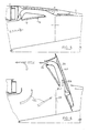
- FIG. 1 of the accompanying drawings shows a known example of an embodiment of a thrust reverser of this type composed of three main parts, a fixed part 1, located upstream, in the extension of the outer wall of the secondary flow channel which is internally delimited by the central structural envelope of the turbojet engine, a mobile part 2 and a fixed rear shell 3.
- Said upstream fixed part 1 comprises an external nacelle panel 4, an internal panel 5 externally limiting the stream of the secondary flow and a frame front 6 which provides the junction of said panels 4 and 5.
- Said front frame 6 also serves as a support for the device for controlling the movements of the mobile part 2 which is essentially composed of a certain number of movable elements, or obstacles commonly called doors 7, this number being able to vary according to the particular applications, for example two, three or four doors 7 forming an annular assembly, if any in cooperation with a fixed part, depending on the assembly method of the assembly propulsion constituted by the turbojet engine on the airplane.
- Figures 2a and 2b show, in a schematic perspective view an example of application of such a thrust reverser to a turbofan engine, the reverser in this case comprising four doors 7 and Figures 2a and 2b show said doors 7, respectively closed and open, corresponding to direct thrust and thrust reverser operation.
- Each door 7 is associated with a movement control means such as a jack 7a.
- each door 7 is composed of an external panel 9 which is placed in the direct jet position in the extension of the external panel 4 of the upstream fixed part 1 to constitute the continuous aerodynamic wall limiting the flow outside the motor represented by the arrow 10, d 'an internal panel 11 and an internal structure 12, ensuring the connection between the panels 9 and 11.
- the door 7 is completed by a set of deflectors intended to channel the reverse flow when the reverser is in the position of reverse thrust and the door 7 in the open or deployed position.
- This assembly comprises in particular upstream of the door 7 a deflector 13 consisting of a front part which may or may not be associated with side parts. So that the door 7, in the open thrust reversal position, provides sufficient performance, it is usually necessary, as in the known example shown in FIG. 1, that the front part of the internal panel 11 move apart, in an external radial direction, of a theoretical surface represented by the line 14, corresponding to a theoretical envelope for perfect continuous aerodynamic delimitation of the stream of the secondary gas flow, represented by the arrow 15.
- a cavity 16 is thus formed on the inside of the door 7 when it is in the closed position corresponding to the direct thrust, delimited at the front by the door deflector 13 and by the deflection edge 8 of the upstream fixed part 1, on the external side, by the front part of the internal door panel 11 and on the side radially internal, by said theoretical surface 14. Part of the flow is forced by the deflection edge 8 into said cavity 16, thereby creating a distortion of the flow and disturbances in the flows. This results in aerodynamic losses which are harmful to direct thrust operation.
- exemplary embodiments of the type of thrust reverser of a turbojet engine with tilting doors are described in particular by FR-A- 2 486 153, FR-A- 2 506 843 and FR-A 2 559 838.
- No fully satisfactory solution n ' was however proposed for an improvement of the vein profile corresponding to an aerodynamic envelope of correct vein in direct thrust operation.
- a solution tending to reduce the volume of the cavity 16 described above with reference to FIG. 1 by bringing the internal face of the front part of the internal panel 11 of the door 7 closer to the theoretical line 14 by means of a reduction the length of the door deflector 13 has the consequence of reducing the efficiency during operation in reverse thrust, which can become unacceptable.
- the object of the invention is to provide a solution to these problems by reconciling the ease of implementation, taking into account the requirements of minimum mass and reduced cost, with obtaining the required performance, both during of direct thrust operation, without aerodynamic losses, that during reverse thrust operation, in particular by ensuring in direct thrust, an internal nacelle line as close as possible to the optimal theoretical profile for delimiting a vein and in reverse thrust, a maximum ejection section.
- a thrust reverser of the aforementioned type with tilting doors capable of deflecting the secondary flow of a turbofan engine characterized in that the internal surface of the internal door panel merges with the aerodynamically optimal surface for delimiting the flow flow stream in the closed door position corresponding to the operation in direct thrust and in that, between said internal panel and the external door panel is provided at least one passage of constant geometry having an opening at each of its ends, on the internal side of said door and forming a mini-flow nozzle so as to increase, during operation in reverse thrust, the ejection section of the reverse flow, part of which flows through said mini-nozzle.
- each door mini-nozzle can be equipped with deflectors arranged so as to optimize the direction of the reverse flow.
- the inlets of said mini-nozzles can advantageously be associated with at least one movable flap capable of closing off said inlet in the direct thrust position and of releasing it during the transition to reverse thrust.
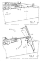
- the thrust reverser of a turbofan engine shown in FIGS. 3 to 6, in an embodiment according to the invention, comprises the main assemblies and elements which have been previously described for a known example of a thrust reverser, with reference to FIGS. 1, 2a and 2b and the same designation references will be kept for identical or corresponding elements, the elements specific to the present embodiment of the invention being assigned a reference increased by a hundred.
- the thrust reverser thus comprises in particular the upstream fixed part 1 composed of the external nacelle panel 4, of the internal panel 5 externally delimiting the vein of the secondary flow represented by the arrow 15, panel 5 which is extended downstream by the edge deflection 8. Said panels 4 and 5 are supported by a front frame 6 which also serves as a support for the jack 7a for controlling the movements of the door 107.
- the thrust reverser door 107 has a rear portion 107b whose internal and external profiles 107c and 107d respectively are in line with the internal and external surfaces 3a respectively and 3b of the fixed rear part 3 of the reverser, an external panel 9 and at the front an assembly forming a deflector 13.
- the door 107 does not have such a cavity that the cavity 16 previously described with reference to FIG. 1.
- the internal door panel 111 deviates towards the front of the external panel 9 to merge its internal surface 111a with the theoretical aerodynamic surface for delimiting the vein of the secondary flow circulating in the secondary channel of the turbojet engine, as can be seen in FIG.
- a passage 20 having on the side internal of the door and at the rear, an opening 21 and likewise, on the internal side of the door but at the front, an opening 22.
- the opening 21 constitutes a inlet, opening 22, outlet and between inlet and outlet
- the passage 20 has an evolution of the sections so as to constitute a mini-nozzle for circulation of an air flow.
- the inverter door 107 during direct thrust operation, the door being closed, as shown in FIGS.
- the actuator 7a for controlling the movements of the door 107 is placed, when the door, in a tunnel forming a housing 23 which is hidden by a closure plate 24, integral with the body of the jack, so as to avoid any disturbance of the flows in the position corresponding to the operation in direct thrust for which the internal surface 2a of said plate 24 is perfectly connected to the internal surface 111a of the internal door panel 111 and merges like it with the optimal aerodynamic surface.
- the door 107 has two passages 20 forming mini-nozzles.
- the door 107 rocks around its pivot axis 25, blocking the passage in the secondary channel and releasing an opening in the outer envelope where the reverse flow shown by arrow 15a engages.
- Part 15b of the reverse flow enters through the inlets 21 into the door mini-nozzles 20 whose profile is adapted to ensure the desired performance and in particular, at the outlet 22 of the mini-nozzles 20, the flow has the pressure and the orientation required to fold the reverse flow towards the front of the turbojet engine and ensure reversal performance.
- the door 107 has a thickness sufficient to effectively reduce the flow in the entire cut corner 107c of the door 107.
- An adjustment of the direction of the reverse flow so as to optimize the aerodynamic interaction with the propelled apparatus is further obtained by means of deflectors 26 which possibly serve as reinforcements of the mini-nozzle 20.
- the movable flap 31 fits perfectly into the opening 21, thereby closing this inlet 21 of the mini-nozzle 20 of the door 207 and ensuring between the internal surface 211a of the panel internal door 211 and the internal surface 207c of the rear part 207b of the door 207 a continuity of the optimal aerodynamic surface.
- the movable flap 31 also carries an attachment point 32 on which is articulated a connecting rod 33 which connects said flap 31 to a drive point 34 secured to the end of the rod of the jack 7a for controlling the movements of the door 207.
- the cylinder rod 7a drives the end 34 of the connecting rod 33 which rotates the flap 31 around its articulated pivot 30.
- the inlet 21 of the mini-nozzle 20 of the door 207 is thus cleared and as previously described with reference to Figures 4 and 6, part of the reverse flow passes through the mini-nozzle 20 and is controlled so as to ensure optimal performance of inversion.
- the position of the flap 31 can be adapted so that said flap serves as a scoop for the reverse flow so as to allow precise adjustment of the part of this reverse flow that is derived in the mini-nozzle 20.
Applications Claiming Priority (2)
| Application Number | Priority Date | Filing Date | Title |
|---|---|---|---|
| FR8814606 | 1988-11-09 | ||
| FR8814606A FR2638784B1 (fr) | 1988-11-09 | 1988-11-09 | Inverseur de poussee de turboreacteur muni de portes a mini-tuyere de deviation du flux inverse |
Publications (2)
| Publication Number | Publication Date |
|---|---|
| EP0368725A1 true EP0368725A1 (de) | 1990-05-16 |
| EP0368725B1 EP0368725B1 (de) | 1992-09-02 |
Family
ID=9371703
Family Applications (1)
| Application Number | Title | Priority Date | Filing Date |
|---|---|---|---|
| EP89403015A Expired - Lifetime EP0368725B1 (de) | 1988-11-09 | 1989-11-02 | Schubumkehrvorrichtung für ein Strahltriebwerk, ausgerüstet mit Umkehrklappen mit Strahlleitdüsen |
Country Status (6)
| Country | Link |
|---|---|
| US (1) | US5040730A (de) |
| EP (1) | EP0368725B1 (de) |
| CA (1) | CA2002466C (de) |
| DE (1) | DE68902727T2 (de) |
| ES (1) | ES2034710T3 (de) |
| FR (1) | FR2638784B1 (de) |
Cited By (4)
| Publication number | Priority date | Publication date | Assignee | Title |
|---|---|---|---|---|
| FR2738597A1 (fr) * | 1995-09-13 | 1997-03-14 | Hispano Suiza Sa | Inverseur de poussee de turboreacteur a portes associees a un panneau primaire |
| EP0836000A1 (de) * | 1996-10-10 | 1998-04-15 | Hispano-Suiza | Klappenschubumkehrvorrichtung mit geregeltem Leckstrom |
| EP0915246A3 (de) * | 1997-11-10 | 2000-07-12 | Rolls-Royce Deutschland GmbH | Schubumkehrvorrichtung eines Flug-Strahltriebwerkes |
| WO2013045787A1 (fr) | 2011-09-29 | 2013-04-04 | Aircelle | Portes d'inverseur de poussée à ouvertures latérales |
Families Citing this family (23)
| Publication number | Priority date | Publication date | Assignee | Title |
|---|---|---|---|---|
| FR2669079B1 (fr) * | 1990-11-14 | 1994-12-30 | Hurel Dubois Avions | Amelioration aux inverseurs de poussee a portes pour avion a reaction. |
| FR2678026B1 (fr) * | 1991-06-24 | 1993-10-15 | Hurel Dubois Avions | Perfectionnement aux inverseurs de poussee de moteur a reaction. |
| US5224342A (en) * | 1992-02-13 | 1993-07-06 | Lair Jean Pierre | Latching and sealing arrangement for jet engine thrust reverser |
| FR2687733B1 (fr) * | 1992-02-26 | 1995-08-04 | Hurel Dubois Avions | Inverseur de poussee pour moteur a reaction assurant un guidage du flux devie. |
| FR2760789B1 (fr) * | 1997-03-13 | 2001-09-07 | Hispano Suiza Sa | Inverseur de poussee de turboreacteur a portes a structure externe autoraidie |
| FR2764339B1 (fr) * | 1997-06-05 | 1999-07-16 | Hispano Suiza Sa | Inverseur de poussee de turboreacteur a portes formant ecopes associees a une casquette amont mobile |
| US6938408B2 (en) * | 2001-04-26 | 2005-09-06 | Propulsion Vectoring, L.P. | Thrust vectoring and variable exhaust area for jet engine nozzle |
| EP1621173B1 (de) * | 2004-07-30 | 2011-03-02 | Hill-Rom Services, Inc. | Fortgeschrittenes Gelenksystem und Matratzenauflage für ein Bett |
| US8015797B2 (en) * | 2006-09-21 | 2011-09-13 | Jean-Pierre Lair | Thrust reverser nozzle for a turbofan gas turbine engine |
| EP2074308B1 (de) * | 2006-10-12 | 2011-12-21 | United Technologies Corporation | Integrierter mechanismus aus einer düse mit variablem querschnitt und schubumkehrvorrichtung |
| US8172175B2 (en) | 2007-11-16 | 2012-05-08 | The Nordam Group, Inc. | Pivoting door thrust reverser for a turbofan gas turbine engine |
| US8052086B2 (en) | 2007-11-16 | 2011-11-08 | The Nordam Group, Inc. | Thrust reverser door |
| US8052085B2 (en) | 2007-11-16 | 2011-11-08 | The Nordam Group, Inc. | Thrust reverser for a turbofan gas turbine engine |
| US7735778B2 (en) | 2007-11-16 | 2010-06-15 | Pratt & Whitney Canada Corp. | Pivoting fairings for a thrust reverser |
| US8091827B2 (en) | 2007-11-16 | 2012-01-10 | The Nordam Group, Inc. | Thrust reverser door |
| US8051639B2 (en) | 2007-11-16 | 2011-11-08 | The Nordam Group, Inc. | Thrust reverser |
| US8127530B2 (en) | 2008-06-19 | 2012-03-06 | The Nordam Group, Inc. | Thrust reverser for a turbofan gas turbine engine |
| FR2965304B1 (fr) * | 2010-09-23 | 2012-10-12 | Airbus Operations Sas | Dispositif de decharge d'air pour turboreacteur d'avion a double flux |
| US9163583B2 (en) * | 2013-05-01 | 2015-10-20 | Rohr, Inc. | System, apparatus, and method for thrust vectoring |
| US9771894B2 (en) | 2013-10-07 | 2017-09-26 | Rohr, Inc. | Radially connected cascade grids |
| US9650992B2 (en) * | 2013-10-17 | 2017-05-16 | Rohr, Inc. | Core cowl thrust reverser system and apparatus |
| US9964071B2 (en) * | 2015-01-13 | 2018-05-08 | Rohr, Inc. | Decoupled translating sleeve |
| DE102016100575A1 (de) | 2016-01-14 | 2017-07-20 | Rolls-Royce Deutschland Ltd & Co Kg | Schubumkehrvorrichtung einer Strömungsmaschine |
Citations (3)
| Publication number | Priority date | Publication date | Assignee | Title |
|---|---|---|---|---|
| GB638063A (en) * | 1945-05-12 | 1950-05-31 | Svenska Turbinfab Ab | Improved means for braking aircraft |
| US3601992A (en) * | 1970-06-10 | 1971-08-31 | Rohr Corp | Thrust reversing apparatus |
| EP0301955A1 (de) * | 1987-07-29 | 1989-02-01 | HISPANO-SUIZA Société anonyme dite: | Schubumkehrvorrichtung für Strahltriebwerke mit einer Strömungshilfsfläche |
Family Cites Families (4)
| Publication number | Priority date | Publication date | Assignee | Title |
|---|---|---|---|---|
| US4093122A (en) * | 1976-11-03 | 1978-06-06 | Rohr Industries, Inc. | Integrated divergent exhaust nozzle thrust reverser |
| FR2506843B1 (fr) * | 1981-05-29 | 1987-04-24 | Hurel Dubois Avions | Dispositif d'inversion de poussee pour turboreacteur d'avion |
| FR2621082A1 (fr) * | 1987-09-30 | 1989-03-31 | Hispano Suiza Sa | Inverseur de poussee de turboreacteur a portes munies d'une plaque au profil de veine |
| US4922712A (en) * | 1988-03-28 | 1990-05-08 | General Electric Company | Thrust reverser for high bypass turbofan engine |
-
1988
- 1988-11-09 FR FR8814606A patent/FR2638784B1/fr not_active Expired - Lifetime
-
1989
- 1989-11-02 ES ES198989403015T patent/ES2034710T3/es not_active Expired - Lifetime
- 1989-11-02 EP EP89403015A patent/EP0368725B1/de not_active Expired - Lifetime
- 1989-11-02 DE DE8989403015T patent/DE68902727T2/de not_active Expired - Fee Related
- 1989-11-07 US US07/432,495 patent/US5040730A/en not_active Expired - Lifetime
- 1989-11-08 CA CA002002466A patent/CA2002466C/fr not_active Expired - Fee Related
Patent Citations (3)
| Publication number | Priority date | Publication date | Assignee | Title |
|---|---|---|---|---|
| GB638063A (en) * | 1945-05-12 | 1950-05-31 | Svenska Turbinfab Ab | Improved means for braking aircraft |
| US3601992A (en) * | 1970-06-10 | 1971-08-31 | Rohr Corp | Thrust reversing apparatus |
| EP0301955A1 (de) * | 1987-07-29 | 1989-02-01 | HISPANO-SUIZA Société anonyme dite: | Schubumkehrvorrichtung für Strahltriebwerke mit einer Strömungshilfsfläche |
Cited By (9)
| Publication number | Priority date | Publication date | Assignee | Title |
|---|---|---|---|---|
| FR2738597A1 (fr) * | 1995-09-13 | 1997-03-14 | Hispano Suiza Sa | Inverseur de poussee de turboreacteur a portes associees a un panneau primaire |
| WO1997010425A1 (fr) * | 1995-09-13 | 1997-03-20 | Societe Hispano Suiza | Inverseur de poussee de turboreacteur a portes associees a un panneau primaire |
| EP0764779A1 (de) * | 1995-09-13 | 1997-03-26 | Hispano Suiza | Schubumkehrvorrichtung mit einem mit Primärteil verbundenen Klappen |
| EP0836000A1 (de) * | 1996-10-10 | 1998-04-15 | Hispano-Suiza | Klappenschubumkehrvorrichtung mit geregeltem Leckstrom |
| WO1998015731A1 (fr) * | 1996-10-10 | 1998-04-16 | Hispano Suiza | Inverseur de poussee a portes a debit de fuite controle |
| FR2754565A1 (fr) * | 1996-10-10 | 1998-04-17 | Hispano Suiza Sa | Inverseur de poussee a portes a debit de fuite controle |
| EP0915246A3 (de) * | 1997-11-10 | 2000-07-12 | Rolls-Royce Deutschland GmbH | Schubumkehrvorrichtung eines Flug-Strahltriebwerkes |
| WO2013045787A1 (fr) | 2011-09-29 | 2013-04-04 | Aircelle | Portes d'inverseur de poussée à ouvertures latérales |
| FR2980825A1 (fr) * | 2011-09-29 | 2013-04-05 | Aircelle Sa | Porte d'inverseur de poussee a ouvertures laterales |
Also Published As
| Publication number | Publication date |
|---|---|
| EP0368725B1 (de) | 1992-09-02 |
| DE68902727D1 (de) | 1992-10-08 |
| CA2002466C (fr) | 1998-11-24 |
| US5040730A (en) | 1991-08-20 |
| FR2638784B1 (fr) | 1990-12-21 |
| CA2002466A1 (en) | 1990-05-09 |
| DE68902727T2 (de) | 1993-03-25 |
| ES2034710T3 (es) | 1993-04-01 |
| FR2638784A1 (fr) | 1990-05-11 |
Similar Documents
| Publication | Publication Date | Title |
|---|---|---|
| EP0368725B1 (de) | Schubumkehrvorrichtung für ein Strahltriebwerk, ausgerüstet mit Umkehrklappen mit Strahlleitdüsen | |
| EP0310497B1 (de) | Schubumkehrvorrichtung für Strahltriebwerke mittels Klappen mit fluchtrechten Innenflächen | |
| EP0301939B1 (de) | Verstellbare Klappe einer Schubumkehrvorrichtung für Strahltriebwerke | |
| EP0338869B1 (de) | Schubumlenkung einer Turbine | |
| EP0414609B1 (de) | Kaskadenschubumkehrvorrichtung ohne Schiebehaube für ein Strahltriebwerk | |
| EP0352171B1 (de) | Schubumkehrvorrichtung für ein Zweikreistriebwerk mit beweglichen Strömungsleitklappen | |
| CA1329487C (fr) | Inverseur de poussee de turboreacteur, a portes pivotantes equilibrees | |
| EP0848153B1 (de) | Schubumkehrvorrichtung für ein Strahltriebwerk mit Umlenkklappen und an der festen Trägerstruktur behalteten Leitflächen | |
| EP0534815B1 (de) | Schubumkehrvorrichtung mit verbesserter Umlenkung der Gasstrahlen | |
| EP0530078B1 (de) | Schubumkehrvorrichtung mit einer gekrümmten Umlenkkante für einen Strahlmotor | |
| EP0822327B1 (de) | Schubumkehrvorrichtung für ein Bläsertriebwerk mit Umkehrklappen, die Kanäle formen | |
| WO1992005356A1 (fr) | Inverseur de poussee de turboreacteur, a portes associees a un panneau amont | |
| WO1998029654A1 (fr) | Inverseur de poussee de turboreacteur a double flux a coquilles aval | |
| FR2982323A1 (fr) | Dispositif d'inversion de poussee | |
| WO1999051870A1 (fr) | Inverseur de poussee de turboreacteur a portes formant ecopes associees a un capotage externe articule | |
| FR2764340A1 (fr) | Inverseur de poussee de turboreacteur a portes munies d'un becquet mobile a entrainement optimise | |
| EP0413635B1 (de) | Schubumkehrvorrichtung für ein Strahltriebwerk | |
| EP0764779A1 (de) | Schubumkehrvorrichtung mit einem mit Primärteil verbundenen Klappen | |
| WO1998055756A1 (fr) | Inverseur de poussee de turboreacteur a portes formant ecopes associees a une casquette amont mobile | |
| EP0807753A1 (de) | Eine Klappe einer Schubumkehrvorrichtung hat eine Auskleidung, die scharnierend an einem Längsträger befestigt ist | |
| EP0728933B1 (de) | Schubumkehrvorrichtung mit dem Hinterteil verbundenen Klappen | |
| FR2648869A1 (fr) | Inverseur de poussee de turboreacteur a portes munies d'une plaque au profil de veine |
Legal Events
| Date | Code | Title | Description |
|---|---|---|---|
| PUAI | Public reference made under article 153(3) epc to a published international application that has entered the european phase |
Free format text: ORIGINAL CODE: 0009012 |
|
| 17P | Request for examination filed |
Effective date: 19891127 |
|
| AK | Designated contracting states |
Kind code of ref document: A1 Designated state(s): BE DE ES FR GB IT SE |
|
| 17Q | First examination report despatched |
Effective date: 19910514 |
|
| GRAA | (expected) grant |
Free format text: ORIGINAL CODE: 0009210 |
|
| ITF | It: translation for a ep patent filed |
Owner name: BARZANO' E ZANARDO MILANO S.P.A. |
|
| AK | Designated contracting states |
Kind code of ref document: B1 Designated state(s): BE DE ES FR GB IT SE |
|
| REF | Corresponds to: |
Ref document number: 68902727 Country of ref document: DE Date of ref document: 19921008 |
|
| GBT | Gb: translation of ep patent filed (gb section 77(6)(a)/1977) | ||
| REG | Reference to a national code |
Ref country code: ES Ref legal event code: FG2A Ref document number: 2034710 Country of ref document: ES Kind code of ref document: T3 |
|
| PLBE | No opposition filed within time limit |
Free format text: ORIGINAL CODE: 0009261 |
|
| STAA | Information on the status of an ep patent application or granted ep patent |
Free format text: STATUS: NO OPPOSITION FILED WITHIN TIME LIMIT |
|
| 26N | No opposition filed | ||
| EAL | Se: european patent in force in sweden |
Ref document number: 89403015.4 |
|
| PGFP | Annual fee paid to national office [announced via postgrant information from national office to epo] |
Ref country code: SE Payment date: 19951013 Year of fee payment: 7 |
|
| PGFP | Annual fee paid to national office [announced via postgrant information from national office to epo] |
Ref country code: BE Payment date: 19951023 Year of fee payment: 7 |
|
| PGFP | Annual fee paid to national office [announced via postgrant information from national office to epo] |
Ref country code: ES Payment date: 19951102 Year of fee payment: 7 |
|
| PG25 | Lapsed in a contracting state [announced via postgrant information from national office to epo] |
Ref country code: SE Effective date: 19961103 |
|
| PG25 | Lapsed in a contracting state [announced via postgrant information from national office to epo] |
Ref country code: ES Free format text: LAPSE BECAUSE OF EXPIRATION OF PROTECTION Effective date: 19961104 |
|
| PG25 | Lapsed in a contracting state [announced via postgrant information from national office to epo] |
Ref country code: BE Effective date: 19961130 |
|
| BERE | Be: lapsed |
Owner name: SOC. DE CONSTRUCTION DES AVIONS HUREL DUBOIS Effective date: 19961130 Owner name: HISPANO-SUIZA Effective date: 19961130 |
|
| EUG | Se: european patent has lapsed |
Ref document number: 89403015.4 |
|
| REG | Reference to a national code |
Ref country code: FR Ref legal event code: TP Ref country code: FR Ref legal event code: CD |
|
| REG | Reference to a national code |
Ref country code: ES Ref legal event code: FD2A Effective date: 20010301 |
|
| REG | Reference to a national code |
Ref country code: GB Ref legal event code: IF02 |
|
| PGFP | Annual fee paid to national office [announced via postgrant information from national office to epo] |
Ref country code: GB Payment date: 20031029 Year of fee payment: 15 |
|
| PGFP | Annual fee paid to national office [announced via postgrant information from national office to epo] |
Ref country code: FR Payment date: 20031127 Year of fee payment: 15 |
|
| PGFP | Annual fee paid to national office [announced via postgrant information from national office to epo] |
Ref country code: DE Payment date: 20040130 Year of fee payment: 15 |
|
| PG25 | Lapsed in a contracting state [announced via postgrant information from national office to epo] |
Ref country code: GB Free format text: LAPSE BECAUSE OF NON-PAYMENT OF DUE FEES Effective date: 20041102 |
|
| PG25 | Lapsed in a contracting state [announced via postgrant information from national office to epo] |
Ref country code: DE Free format text: LAPSE BECAUSE OF NON-PAYMENT OF DUE FEES Effective date: 20050601 |
|
| GBPC | Gb: european patent ceased through non-payment of renewal fee |
Effective date: 20041102 |
|
| PG25 | Lapsed in a contracting state [announced via postgrant information from national office to epo] |
Ref country code: FR Free format text: LAPSE BECAUSE OF NON-PAYMENT OF DUE FEES Effective date: 20050729 |
|
| REG | Reference to a national code |
Ref country code: FR Ref legal event code: ST |
|
| PG25 | Lapsed in a contracting state [announced via postgrant information from national office to epo] |
Ref country code: IT Free format text: LAPSE BECAUSE OF NON-PAYMENT OF DUE FEES;WARNING: LAPSES OF ITALIAN PATENTS WITH EFFECTIVE DATE BEFORE 2007 MAY HAVE OCCURRED AT ANY TIME BEFORE 2007. THE CORRECT EFFECTIVE DATE MAY BE DIFFERENT FROM THE ONE RECORDED. Effective date: 20051102 |