EP0368471A1 - Pedestal chair - Google Patents
Pedestal chair Download PDFInfo
- Publication number
- EP0368471A1 EP0368471A1 EP89310208A EP89310208A EP0368471A1 EP 0368471 A1 EP0368471 A1 EP 0368471A1 EP 89310208 A EP89310208 A EP 89310208A EP 89310208 A EP89310208 A EP 89310208A EP 0368471 A1 EP0368471 A1 EP 0368471A1
- Authority
- EP
- European Patent Office
- Prior art keywords
- axis
- frame member
- chassis member
- block
- occupant
- Prior art date
- Legal status (The legal status is an assumption and is not a legal conclusion. Google has not performed a legal analysis and makes no representation as to the accuracy of the status listed.)
- Withdrawn
Links
Images


Classifications
-
- A—HUMAN NECESSITIES
- A47—FURNITURE; DOMESTIC ARTICLES OR APPLIANCES; COFFEE MILLS; SPICE MILLS; SUCTION CLEANERS IN GENERAL
- A47C—CHAIRS; SOFAS; BEDS
- A47C1/00—Chairs adapted for special purposes
- A47C1/02—Reclining or easy chairs
- A47C1/031—Reclining or easy chairs having coupled concurrently adjustable supporting parts
- A47C1/032—Reclining or easy chairs having coupled concurrently adjustable supporting parts the parts being movably-coupled seat and back-rest
- A47C1/03255—Reclining or easy chairs having coupled concurrently adjustable supporting parts the parts being movably-coupled seat and back-rest with a central column, e.g. rocking office chairs
-
- A—HUMAN NECESSITIES
- A47—FURNITURE; DOMESTIC ARTICLES OR APPLIANCES; COFFEE MILLS; SPICE MILLS; SUCTION CLEANERS IN GENERAL
- A47C—CHAIRS; SOFAS; BEDS
- A47C1/00—Chairs adapted for special purposes
- A47C1/02—Reclining or easy chairs
- A47C1/031—Reclining or easy chairs having coupled concurrently adjustable supporting parts
- A47C1/032—Reclining or easy chairs having coupled concurrently adjustable supporting parts the parts being movably-coupled seat and back-rest
- A47C1/03261—Reclining or easy chairs having coupled concurrently adjustable supporting parts the parts being movably-coupled seat and back-rest characterised by elastic means
- A47C1/03266—Reclining or easy chairs having coupled concurrently adjustable supporting parts the parts being movably-coupled seat and back-rest characterised by elastic means with adjustable elasticity
-
- A—HUMAN NECESSITIES
- A47—FURNITURE; DOMESTIC ARTICLES OR APPLIANCES; COFFEE MILLS; SPICE MILLS; SUCTION CLEANERS IN GENERAL
- A47C—CHAIRS; SOFAS; BEDS
- A47C1/00—Chairs adapted for special purposes
- A47C1/02—Reclining or easy chairs
- A47C1/031—Reclining or easy chairs having coupled concurrently adjustable supporting parts
- A47C1/032—Reclining or easy chairs having coupled concurrently adjustable supporting parts the parts being movably-coupled seat and back-rest
- A47C1/03261—Reclining or easy chairs having coupled concurrently adjustable supporting parts the parts being movably-coupled seat and back-rest characterised by elastic means
- A47C1/03288—Reclining or easy chairs having coupled concurrently adjustable supporting parts the parts being movably-coupled seat and back-rest characterised by elastic means with resilient blocks
Definitions
- This invention relates to pedestal chairs.
- a pedestal chair comprises a spindle, a frame member secured on the spindle, a seat chassis member pivotally mounted on the frame member about a first transverse horizontal axis, a back support stem pivotally mounted on the frame member about a second transverse horizontal axis, the first axis being disposed adjacent the front of the chair, the second axis being disposed behind the first axis, and the chassis member and back support stem extending rearwardly of the second axis and being pivotally interconnected about a third transverse horizontal axis disposed rearwardly of the second axis, and a spring acting between the frame member and the seat chassis member and urging the latter to a forwardly tilted position from which an occupant may tilt the chassis member backwardly about the first axis, with attendant rearward pivotal movement of the back support stem about the second axis, to an extent dependent on the occupant's weight and weight distribution.
- the spring may be a compressible block of elastomeric material and its degree of compression may be adjustable in order to suit the occupant's weight.
- the second axis is nearer to the first axis than the third axis.
- the system then acts as a second order lever, the restraining force (provided by the spring) being intermediate the pivot (provided by the first axis) and the load (provided by the weight of the occupant).
- the chair comprises a pedestal or spindle 10 on the upper end of which is rigidly secured a frame member 12.
- the frame member 12 is of channel section with out-turned flanges, as best shown in Figure 4.
- a seat chassis member 14 is pivotally mounted on the frame member 12 about a first transverse horizontal axis defined by a pivot pin 16.
- a back support stem 18 is pivotally mounted on the frame member 12 about a second horizontal transverse axis defined by a pin 20.
- the back support stem 18 extends rearwardly, curving gently upwardly, to a third transverse horizontal axis (defined by pin 22) where the rear of the chassis member 14 is pivotally connected to the back support stem 18.
- the first, second and third axes are parallel, with the first axis being disposed adjacent the front of the chassis, the second axis being disposed rearwardly of the first axis and the third axis being disposed towards the rear of the chassis, with the second axis being nearer to the first axis than to the third axis.
- a compressible block 24 of elastomeric material surrounds a rod 26, one end of which carries an end cap 28 and the other end of which passes through a hole in the base of the frame member 12 and is anchored by being threaded into a nut 30 ( Figure 4).
- the block 24 of elastomeric material is located between the underside of the chassis member 14 and the cap 28. Rotation of the cap 28 alters the degree of compression of the block 24 and hence the spring force tending to restore the chair to the forward tilt position shown in Figure 1.
- the cap 28 may either be screw threaded on the rod 26 which is then fixed in the nut 30, or the cap 28 may be fixed on the rod 26 and the latter screw threaded in the nut 30.
- the block 24 When the chair is unoccupied the block 24 will urge the chassis member 14 to the forwardly tilted position and the back stem 18 to an upright position, as illustrated in Figure 1. In this limit position, the chassis member engages the underside of the frame member 12. When an occupant sits in the chair, the occupant's weight will tend to tilt the chassis member 14 rearwardly from the position shown in Figure 1 towards the position shown in Figure 2. Rearward tilting movement of the chassis member 14 about the pin 16 will be accompanied by corresponding rearward tilting of the back stem 18 about the pin 20, so that the back stem will automatically recline as the occupant moves his weight backwards. With the occupant's weight centrally distributed, the chair will assume a neutral position intermediate the forward tilt position of Figure 1 and the rearward tilt position of Figure 2. When the user leans forward the chassis member 14 and stem 18 will pivot forwardly and when the occupant leans back the chassis member 14 and stem 18 will pivot rearwardly. Maximum compression of the block 24 defines the limit positon of Figure 2.
- the back support stem 18 will carry a chair back.
- the chassis member 14 has holes 32 for securing a seat base to the chassis member which also has oppositely extending projections 34 to which may be secured arms for the chair.
Abstract
A pedestal chair comprises a spindle (10) to which is rigidly attached a frame member (12). A seat chassis member (14) is pivotally mounted on the frame member (12) about a first transverse horizontal axis (16). At its forward end a back support stem (18) is pivotally mounted on the frame member (12) about a second transverse horizontal axis (20). The rear of the chassis member (14) is pivotally attached to the base support stem (18) about a third horizontal axis (22). An elastomeric block (24) urges the chassis member (14) to a forwardly tilted position (Figure 1), from which an occupant's weight tends to tilt the chassis member (14) rearwardly towards a rearwardly tilted position (Figure 2).
Description
- This invention relates to pedestal chairs.
- According to the invention a pedestal chair comprises a spindle, a frame member secured on the spindle, a seat chassis member pivotally mounted on the frame member about a first transverse horizontal axis, a back support stem pivotally mounted on the frame member about a second transverse horizontal axis, the first axis being disposed adjacent the front of the chair, the second axis being disposed behind the first axis, and the chassis member and back support stem extending rearwardly of the second axis and being pivotally interconnected about a third transverse horizontal axis disposed rearwardly of the second axis, and a spring acting between the frame member and the seat chassis member and urging the latter to a forwardly tilted position from which an occupant may tilt the chassis member backwardly about the first axis, with attendant rearward pivotal movement of the back support stem about the second axis, to an extent dependent on the occupant's weight and weight distribution.
- This contrasts with known chairs which have linkages between the back support stem and the frame member and do not have in an equivalent structure the facility of rearward tilting of a chassis member (against spring bias) from a transverse front pivot axis, with attendant reclining movement of a back support stem.
- The spring may be a compressible block of elastomeric material and its degree of compression may be adjustable in order to suit the occupant's weight.
- Preferably, the second axis is nearer to the first axis than the third axis. The system then acts as a second order lever, the restraining force (provided by the spring) being intermediate the pivot (provided by the first axis) and the load (provided by the weight of the occupant).
- The chassis of a chair according to the invention will now be described by way of example with reference to the accompanying drawings in which:
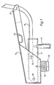
- Figure 1 is a side view of the chassis in a position of forward tilt,
- Figure 2 is a similar view in a position of rearward tilt,
- Figure 3 is a plan view of the chassis, and
- Figure 4 is a front view.
- Referring to the drawings, the chair comprises a pedestal or
spindle 10 on the upper end of which is rigidly secured aframe member 12. Theframe member 12 is of channel section with out-turned flanges, as best shown in Figure 4. Aseat chassis member 14 is pivotally mounted on theframe member 12 about a first transverse horizontal axis defined by apivot pin 16. At its forward end, aback support stem 18 is pivotally mounted on theframe member 12 about a second horizontal transverse axis defined by apin 20. - The
back support stem 18 extends rearwardly, curving gently upwardly, to a third transverse horizontal axis (defined by pin 22) where the rear of thechassis member 14 is pivotally connected to theback support stem 18. The first, second and third axes are parallel, with the first axis being disposed adjacent the front of the chassis, the second axis being disposed rearwardly of the first axis and the third axis being disposed towards the rear of the chassis, with the second axis being nearer to the first axis than to the third axis. - A
compressible block 24 of elastomeric material surrounds arod 26, one end of which carries anend cap 28 and the other end of which passes through a hole in the base of theframe member 12 and is anchored by being threaded into a nut 30 (Figure 4). Theblock 24 of elastomeric material is located between the underside of thechassis member 14 and thecap 28. Rotation of thecap 28 alters the degree of compression of theblock 24 and hence the spring force tending to restore the chair to the forward tilt position shown in Figure 1. Thecap 28 may either be screw threaded on therod 26 which is then fixed in thenut 30, or thecap 28 may be fixed on therod 26 and the latter screw threaded in thenut 30. - When the chair is unoccupied the
block 24 will urge thechassis member 14 to the forwardly tilted position and theback stem 18 to an upright position, as illustrated in Figure 1. In this limit position, the chassis member engages the underside of theframe member 12. When an occupant sits in the chair, the occupant's weight will tend to tilt thechassis member 14 rearwardly from the position shown in Figure 1 towards the position shown in Figure 2. Rearward tilting movement of thechassis member 14 about thepin 16 will be accompanied by corresponding rearward tilting of theback stem 18 about thepin 20, so that the back stem will automatically recline as the occupant moves his weight backwards. With the occupant's weight centrally distributed, the chair will assume a neutral position intermediate the forward tilt position of Figure 1 and the rearward tilt position of Figure 2. When the user leans forward thechassis member 14 andstem 18 will pivot forwardly and when the occupant leans back thechassis member 14 andstem 18 will pivot rearwardly. Maximum compression of theblock 24 defines the limit positon of Figure 2. - The
back support stem 18 will carry a chair back. Thechassis member 14 hasholes 32 for securing a seat base to the chassis member which also has oppositely extendingprojections 34 to which may be secured arms for the chair. - It will be appreciated that the three pivot axes have sufficient play to enable the
chassis member 14 andback support stem 18 to undergo the limited range of pivotal movement between the limit positions illustrated in Figures 1 and 2.
Claims (6)
1. A pedestal chair comprising a spindle, a frame member secured on the spindle, a seat chassis member pivotally mounted on the frame member about a first transverse horizontal axis, a back support stem pivotally mounted on the frame member about a second transverse horizontal axis, the first axis being disposed adjacent the front of the chair, the second axis being disposed behind the first axis, and the chassis member and back support stem extending rearwardly of the second axis and being pivotally interconnected about a third transverse horizontal axis disposed rearwardly of the second axis, and a spring acting between the frame member and the seat chassis member and urging the latter to a forwardly tilted position from which an occupant may tilt the chassis member backwardly about the first axis, with attendant rearward pivotal movement of the back support stem about the second axis, to an extent dependent on the occupant's weight and weight distribution.
2. A pedestal chair according to claim 1, wherein the spring is a compressible block of elastomeric material.
3. A pedestal chair according to claim 2, wherein the block surrounds a rod, one end of which carries an end cap and the other end of which is anchored in the frame member, the block being compressed between the cap and the underside of the chassis member.
4. A pedestal chair according to claim 2 or 3, wherein the degree of compression of the block is adjustable in order to suit the occupant's weight.
5. A pedestal chair according to claims 3 and 4, wherein the degree of compression of the block is adjustable by rotation of the end cap.
6. A pedestal chair according to any of the preceding claims, wherein the second axis is nearer to the first axis than the third axis.
Applications Claiming Priority (2)
| Application Number | Priority Date | Filing Date | Title |
|---|---|---|---|
| GB888825077A GB8825077D0 (en) | 1988-10-26 | 1988-10-26 | Pedestal chair |
| GB8825077 | 1988-10-26 |
Publications (1)
| Publication Number | Publication Date |
|---|---|
| EP0368471A1 true EP0368471A1 (en) | 1990-05-16 |
Family
ID=10645835
Family Applications (1)
| Application Number | Title | Priority Date | Filing Date |
|---|---|---|---|
| EP89310208A Withdrawn EP0368471A1 (en) | 1988-10-26 | 1989-10-05 | Pedestal chair |
Country Status (2)
| Country | Link |
|---|---|
| EP (1) | EP0368471A1 (en) |
| GB (1) | GB8825077D0 (en) |
Cited By (3)
| Publication number | Priority date | Publication date | Assignee | Title |
|---|---|---|---|---|
| DE4212573A1 (en) * | 1992-04-15 | 1993-10-21 | Claus Uredat | Chair with incline adjustable backrest and seat - has elastic link between part of the backrest and the seat frame to counteract incline adjustment. |
| EP1197167A3 (en) * | 2000-10-10 | 2003-07-30 | Rodd Engineering Limited | Chair tilting mechanism and a chair incorporating such a mechanism |
| EP2364616A1 (en) * | 2010-03-09 | 2011-09-14 | Kinnarps Samas GmbH | Chair |
Citations (3)
| Publication number | Priority date | Publication date | Assignee | Title |
|---|---|---|---|---|
| DE3139448A1 (en) * | 1981-10-03 | 1983-04-21 | Kusch & Co Sitzmöbelwerke KG, 5789 Hallenberg | "CHAIR" |
| DE3322450A1 (en) * | 1983-06-22 | 1985-01-10 | August Fröscher GmbH & Co KG, 7141 Steinheim | Device for adjusting the seat and the backrest of chairs |
| DE3605809A1 (en) * | 1986-02-22 | 1987-08-27 | Koenig & Neurath Kg | Piece of seating furniture |
-
1988
- 1988-10-26 GB GB888825077A patent/GB8825077D0/en active Pending
-
1989
- 1989-10-05 EP EP89310208A patent/EP0368471A1/en not_active Withdrawn
Patent Citations (3)
| Publication number | Priority date | Publication date | Assignee | Title |
|---|---|---|---|---|
| DE3139448A1 (en) * | 1981-10-03 | 1983-04-21 | Kusch & Co Sitzmöbelwerke KG, 5789 Hallenberg | "CHAIR" |
| DE3322450A1 (en) * | 1983-06-22 | 1985-01-10 | August Fröscher GmbH & Co KG, 7141 Steinheim | Device for adjusting the seat and the backrest of chairs |
| DE3605809A1 (en) * | 1986-02-22 | 1987-08-27 | Koenig & Neurath Kg | Piece of seating furniture |
Cited By (4)
| Publication number | Priority date | Publication date | Assignee | Title |
|---|---|---|---|---|
| DE4212573A1 (en) * | 1992-04-15 | 1993-10-21 | Claus Uredat | Chair with incline adjustable backrest and seat - has elastic link between part of the backrest and the seat frame to counteract incline adjustment. |
| EP1197167A3 (en) * | 2000-10-10 | 2003-07-30 | Rodd Engineering Limited | Chair tilting mechanism and a chair incorporating such a mechanism |
| EP2364616A1 (en) * | 2010-03-09 | 2011-09-14 | Kinnarps Samas GmbH | Chair |
| DE102010015866B4 (en) | 2010-03-09 | 2022-01-20 | Kinnarps Ab | chair |
Also Published As
| Publication number | Publication date |
|---|---|
| GB8825077D0 (en) | 1988-11-30 |
Similar Documents
| Publication | Publication Date | Title |
|---|---|---|
| US4685730A (en) | Seat, especially work seat, with several positions | |
| EP0283170B1 (en) | Improvements in pedestal chairs | |
| US4533177A (en) | Reclining chair | |
| US4270797A (en) | Ergonomic chair | |
| US5501507A (en) | Seat with spring-loaded lumbar support | |
| US6109694A (en) | Chair with four-bar linkage for self-adjusting back tension | |
| US5308145A (en) | Reclining chair | |
| EP1328176B1 (en) | Armchair with variable position | |
| US4558901A (en) | Arm rest device of a seat for a vehicle | |
| US5868468A (en) | Chair with adjustable inclination | |
| EP0614633B1 (en) | Adjustbale backrest for a chair | |
| US4575151A (en) | Chair tilting mechanism | |
| US7497515B2 (en) | Ergonomic chair | |
| US4789203A (en) | Chair with movable seat and backrest | |
| US6969116B2 (en) | Chair with backward and forward passive tilt capabilities | |
| US4007962A (en) | Chair with adjustable back | |
| US4756575A (en) | Frame assembly for a chair | |
| JPH01500406A (en) | Tilt mechanism for chair seats etc. | |
| US4504090A (en) | Swivel, tilt and recline arm chair | |
| US4880272A (en) | Seat furniture | |
| US4938532A (en) | Seating apparatus | |
| US5452937A (en) | Plate for connecting the seat, back and legs, especially for chairs | |
| EP0250207A2 (en) | Improvements in and relating to adjustable chairs | |
| US5259663A (en) | Chair seat mounting mechanism | |
| CA1156136A (en) | Mounting device for a chair seat |
Legal Events
| Date | Code | Title | Description |
|---|---|---|---|
| PUAI | Public reference made under article 153(3) epc to a published international application that has entered the european phase |
Free format text: ORIGINAL CODE: 0009012 |
|
| AK | Designated contracting states |
Kind code of ref document: A1 Designated state(s): AT BE CH DE ES FR GB GR IT LI LU NL SE |
|
| STAA | Information on the status of an ep patent application or granted ep patent |
Free format text: STATUS: THE APPLICATION IS DEEMED TO BE WITHDRAWN |
|
| 18D | Application deemed to be withdrawn |
Effective date: 19901117 |