EP0368386B1 - Steering wheel for motor vehicles with connecting plates between spokes and rim - Google Patents
Steering wheel for motor vehicles with connecting plates between spokes and rim Download PDFInfo
- Publication number
- EP0368386B1 EP0368386B1 EP89202721A EP89202721A EP0368386B1 EP 0368386 B1 EP0368386 B1 EP 0368386B1 EP 89202721 A EP89202721 A EP 89202721A EP 89202721 A EP89202721 A EP 89202721A EP 0368386 B1 EP0368386 B1 EP 0368386B1
- Authority
- EP
- European Patent Office
- Prior art keywords
- steering wheel
- plate
- spokes
- motor vehicles
- rim
- Prior art date
- Legal status (The legal status is an assumption and is not a legal conclusion. Google has not performed a legal analysis and makes no representation as to the accuracy of the status listed.)
- Expired - Lifetime
Links
- 230000000295 complement effect Effects 0.000 claims description 2
- 239000007769 metal material Substances 0.000 claims description 2
- 238000004140 cleaning Methods 0.000 description 3
- 239000000428 dust Substances 0.000 description 3
- 238000004519 manufacturing process Methods 0.000 description 2
- 230000003749 cleanliness Effects 0.000 description 1
- 239000011248 coating agent Substances 0.000 description 1
- 238000000576 coating method Methods 0.000 description 1
- 230000007547 defect Effects 0.000 description 1
- 239000010985 leather Substances 0.000 description 1
- 239000003973 paint Substances 0.000 description 1
- 230000000737 periodic effect Effects 0.000 description 1
- 235000019640 taste Nutrition 0.000 description 1
Images
Classifications
-
- B—PERFORMING OPERATIONS; TRANSPORTING
- B62—LAND VEHICLES FOR TRAVELLING OTHERWISE THAN ON RAILS
- B62D—MOTOR VEHICLES; TRAILERS
- B62D1/00—Steering controls, i.e. means for initiating a change of direction of the vehicle
- B62D1/02—Steering controls, i.e. means for initiating a change of direction of the vehicle vehicle-mounted
- B62D1/04—Hand wheels
Definitions
- the present invention relates to a steering wheel for motor vehicles with covering plates between spokes and rim.
- the conventional steering wheel of a motor vehicle is normally constituted by a central part provided with a system for fastening it to the steering column, from which there extends a plurality of radial spokes connected with an external circular rim, either directly or through connecting plates as shown in DE-A-3 508 380.
- junction areas between the spokes and the rim constitute critical points as regards aesthetics and cleanliness.
- leather steering wheels for example, the finish at the base of the spokes leaves frequently something to be desired.
- residues of rim paint may remain, requiring considerable expenditure of time for their removal.
- the above junction areas tend to become places where dust collects, requiring accurate periodical cleaning.
- the use of the driver's hands for the maneuverability of the steering wheel is not ideal in those areas.
- the primary object of the present invention is that of accomplishing a steering wheel capable of solving the above problems arising with the connection of spokes and rim.
- a steering wheel for motor vehicles comprising a central part from which there extends a plurality of radial spokes fitted in an external circular rim, characterized in that the external ends of the spokes at their connecting areas with the external rim are provided with shaped covering plates.
- the connecting areas of the spokes with the rim no longer constitute areas where dust and dirt collect, so that it is no longer necessary to proceed with an accurate periodic cleaning of the areas themselves.
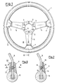
- a steering wheel 1 for motor vehicles has a central part 2 in which there are provided a central positioning hole 4 and a plurality of lateral fastening holes 3 for the application to the steering column of a motor vehicle. From the central part 2 there extends in a radial direction a plurality of spokes 5, which fit in a rim 6 at the other extremity. At the point wherein the spokes 5 meet the rim 6 there is provided a plurality of shaped plates 7 which cover the connecting areas between said spokes 5 and said rim 6.
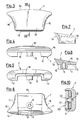
- These plates are shaped as shown in Fig.s from 3 to 8 and comprise an open external surface 10 having an inclined profile with rounded concave lateral sides 16 and an internal surface 11 interrupted by a groove 12 which extends along the entire height of the plate 7 and whose internal dimensions are equal to the external dimensions of a spoke at the junction point.
- a rise 13 in which there is obtained a drilled seat 9, in which the fastening screw 8 is screwed with its head reacting against the face of the spoke opposite that on which the plate rests.
- An extremity 14 is shaped so as to mate perfectly with the steering wheel's rim 6 (Fig. 2) so as not to cause a discontinuity in the shape.
- the other extremity 15 is in turn rounded and tapered so as to mate perfectly with the surface of the spoke 5 on which the plate 7 is fitted.
- the same plate of Fig.s 3-8 or one slightly different may be fastened to the respective spoke of the steering wheel by means of a complementary counter-plate 20, which together with the plate 7 embraces the spoke 5 in the area where it joins the rim 6.
- a fastening screw 21 having a conical head inserted in a suitable seat 22 of the counter-plate 20, with consequent further improvement in the aesthetics and in the maneuverability of the steering wheel.
- the plate described above may be applied to any steering wheel for motor vehicles, even if it is very different from that of Fig. 1, so as to hide from view the areas wherein dust or any manufacturing residues may accumulate, avoiding the necessity of an accurate cleaning in those areas.
- the curvilinear shape of the plate gives the steering wheel a greater practicality of use as it is of an anatomical type.
- the plate improves the aesthetics of the steering wheel itself as it constitutes a decorative element.
- Plate 7 may be of metallic material, and it is also possible with the occasion to provide a particular coating of this plate 7 to meet the different tastes of the motor car enthusiast.
Landscapes
- Engineering & Computer Science (AREA)
- Chemical & Material Sciences (AREA)
- Combustion & Propulsion (AREA)
- Transportation (AREA)
- Mechanical Engineering (AREA)
- Steering Controls (AREA)
Abstract
Description
- The present invention relates to a steering wheel for motor vehicles with covering plates between spokes and rim.
- The conventional steering wheel of a motor vehicle is normally constituted by a central part provided with a system for fastening it to the steering column, from which there extends a plurality of radial spokes connected with an external circular rim, either directly or through connecting plates as shown in DE-A-3 508 380.
- In the usual motor vehicle steering wheels the junction areas between the spokes and the rim constitute critical points as regards aesthetics and cleanliness. In leather steering wheels, for example, the finish at the base of the spokes leaves frequently something to be desired. On the other hand, in the case of wooden steering wheels, residues of rim paint may remain, requiring considerable expenditure of time for their removal. Also during use the above junction areas tend to become places where dust collects, requiring accurate periodical cleaning. Lastly, the use of the driver's hands for the maneuverability of the steering wheel is not ideal in those areas.
- The primary object of the present invention is that of accomplishing a steering wheel capable of solving the above problems arising with the connection of spokes and rim.
- According to the invention such object is attained with a steering wheel for motor vehicles comprising a central part from which there extends a plurality of radial spokes fitted in an external circular rim, characterized in that the external ends of the spokes at their connecting areas with the external rim are provided with shaped covering plates.
- The use of such plates substantially improves the aesthetics of the steering wheel, since the plates themselves constitute a pleasant decorative element, which covers the manufacturing defects, if any.
- Moreover, the connecting areas of the spokes with the rim no longer constitute areas where dust and dirt collect, so that it is no longer necessary to proceed with an accurate periodic cleaning of the areas themselves.
- Lastly, if an appropriate anatomical shape is given to the plates, the maneuverability of the steering wheel is also improved.
- These and other characteristics of the present invention shall be made evident by the following detailed description of its embodiments illustrated as an example in the enclosed drawings, wherein:
- Fig. 1 is a plan view of a steering wheel according to the present invention;
- Fig. 2 is a cross-sectional view taken along the line II-II of Fig. 1, which shows in an enlarged scale one of the connecting areas between the spokes and the external rim of the above steering wheel;
- Fig. 3 shows a plan view from above of one of the covering plates superimposed over said connecting areas;
- Fig. 4 shows said plate seen from above with respect to Fig. 3;
- Fig. 5 shows said plate seen from below with respect to Fig. 3;
- Fig. 6 shows said plate in a plan view from below;
- Fig. 7 shows said plate seen from the left hand side with respect to Fig. 3;
- Fig. 8 shows said plate seen in cross-section along the line VIII-VIII of Fig. 3;
- Fig. 9 shows in cross-section as in Fig. 2 a different type of fastening of the plate of Fig.s 3-8;
- Fig. 10 shows the detail of Fig. 9 in cross-section along the line X-X of the same figure.
- With reference to Fig.s 1 and 2, a steering wheel 1 for motor vehicles has a
central part 2 in which there are provided a central positioning hole 4 and a plurality oflateral fastening holes 3 for the application to the steering column of a motor vehicle. From thecentral part 2 there extends in a radial direction a plurality ofspokes 5, which fit in arim 6 at the other extremity. At the point wherein thespokes 5 meet therim 6 there is provided a plurality ofshaped plates 7 which cover the connecting areas between saidspokes 5 and saidrim 6. - These
plates 7, equal in number to that of thespokes 5, are fastened to thespokes 5 by means of a screw 8 which passes through the spoke and is screwed into a suitable drilledseat 9 obtained in theplates 7. - These plates, in the illustrated example, are shaped as shown in Fig.s from 3 to 8 and comprise an open
external surface 10 having an inclined profile with rounded concavelateral sides 16 and aninternal surface 11 interrupted by agroove 12 which extends along the entire height of theplate 7 and whose internal dimensions are equal to the external dimensions of a spoke at the junction point. In the central part of thegroove 12 there is arise 13 in which there is obtained a drilledseat 9, in which the fastening screw 8 is screwed with its head reacting against the face of the spoke opposite that on which the plate rests. Anextremity 14 is shaped so as to mate perfectly with the steering wheel's rim 6 (Fig. 2) so as not to cause a discontinuity in the shape. Theother extremity 15 is in turn rounded and tapered so as to mate perfectly with the surface of thespoke 5 on which theplate 7 is fitted. - As an alternative, as shown in Fig.s 9 and 10, the same plate of Fig.s 3-8 or one slightly different may be fastened to the respective spoke of the steering wheel by means of a
complementary counter-plate 20, which together with theplate 7 embraces thespoke 5 in the area where it joins therim 6. In which case it is possible to use a fasteningscrew 21 having a conical head inserted in asuitable seat 22 of thecounter-plate 20, with consequent further improvement in the aesthetics and in the maneuverability of the steering wheel. - The plate described above may be applied to any steering wheel for motor vehicles, even if it is very different from that of Fig. 1, so as to hide from view the areas wherein dust or any manufacturing residues may accumulate, avoiding the necessity of an accurate cleaning in those areas. In addition, the curvilinear shape of the plate gives the steering wheel a greater practicality of use as it is of an anatomical type. Lastly, the plate improves the aesthetics of the steering wheel itself as it constitutes a decorative element.
-
Plate 7 may be of metallic material, and it is also possible with the occasion to provide a particular coating of thisplate 7 to meet the different tastes of the motor car enthusiast.
Claims (5)
- Steering wheel for motor vehicles comprising a central part (2) from which there extends a plurality of radial spokes (5) fitted in an external circular rim (6), characterized in that the external ends of the spokes (5) at their connecting areas with the external rim (6) are provided with shaped covering plates (7).
- Steering wheel for motor vehicles according to claim 1, characterized in that said plates (7) include an external open surface (10) having an inclined profile with rounded concave sides (16) which aesthetically and functionally mate the shape of the radial spokes (5) and the circular rim (6) and an internal surface (11) interrupted by a groove (12) extending along the entire height of the plate (7) and whose internal dimensions are equal to the external dimensions of a spoke (5) of a steering wheel (1), there being provided means (8; 20, 21) for fastening said plate (7) to said spokes (5).
- Steering wheel for motor vehicles according to claim 2, characterized in that said fastening means (8; 20, 21) are constituted by a screw (8) with its head reacting against the face of the spoke (5) opposite to that against which the plate (7) rests.
- Steering wheel for motor vehicles according to claim 2, characterized in that said fastening means (8; 20, 21) comprise a counter-plate (20) shaped in a complementary way with respect to said plate (7) and applied to the face of the spoke (5) opposite to that against which the plate (7) rests, and a fastening screw (21) with its head embedded in a seat (22) of said counter-plate (20).
- Steering wheel for motor vehicles according to claim 1, characterized in that said plates (7) are of metallic material.
Priority Applications (1)
| Application Number | Priority Date | Filing Date | Title |
|---|---|---|---|
| AT89202721T ATE92412T1 (en) | 1988-11-09 | 1989-10-26 | STEERING WHEEL FOR MOTOR VEHICLES WITH FIXING PLATES BETWEEN SPOKES AND RIM. |
Applications Claiming Priority (2)
| Application Number | Priority Date | Filing Date | Title |
|---|---|---|---|
| IT8822122U IT215383Z2 (en) | 1988-11-09 | 1988-11-09 | MOTOR VEHICLE STEERING WHEEL WITH CONNECTION PLATES BETWEEN SPOKES AND CROWN. |
| IT2212288U | 1988-11-09 |
Publications (3)
| Publication Number | Publication Date |
|---|---|
| EP0368386A2 EP0368386A2 (en) | 1990-05-16 |
| EP0368386A3 EP0368386A3 (en) | 1990-09-26 |
| EP0368386B1 true EP0368386B1 (en) | 1993-08-04 |
Family
ID=11191820
Family Applications (1)
| Application Number | Title | Priority Date | Filing Date |
|---|---|---|---|
| EP89202721A Expired - Lifetime EP0368386B1 (en) | 1988-11-09 | 1989-10-26 | Steering wheel for motor vehicles with connecting plates between spokes and rim |
Country Status (4)
| Country | Link |
|---|---|
| EP (1) | EP0368386B1 (en) |
| AT (1) | ATE92412T1 (en) |
| DE (1) | DE68908085T2 (en) |
| IT (1) | IT215383Z2 (en) |
Families Citing this family (2)
| Publication number | Priority date | Publication date | Assignee | Title |
|---|---|---|---|---|
| FR2774348B1 (en) | 1998-02-04 | 2000-03-03 | Roulements Soc Nouvelle | STEERING WHEEL ARM WITH INTEGRATED OR RELATED TORQUE SENSOR FOR VEHICLE STEERING DEVICE |
| JP7558759B2 (en) * | 2020-11-05 | 2024-10-01 | Joyson Safety Systems Japan合同会社 | Steering wheel core structure |
Family Cites Families (3)
| Publication number | Priority date | Publication date | Assignee | Title |
|---|---|---|---|---|
| GB546935A (en) * | 1941-02-11 | 1942-08-06 | Joseph Duthie Birnie | Improvements in steering wheels |
| JPS60145965U (en) * | 1984-03-10 | 1985-09-27 | 豊田合成株式会社 | Core material for steering wheels |
| DE3509302A1 (en) * | 1985-03-15 | 1986-09-25 | Carl Kittel GmbH & Co KG, 8057 Eching | Steering wheel for motor vehicles |
-
1988
- 1988-11-09 IT IT8822122U patent/IT215383Z2/en active
-
1989
- 1989-10-26 DE DE89202721T patent/DE68908085T2/en not_active Expired - Fee Related
- 1989-10-26 EP EP89202721A patent/EP0368386B1/en not_active Expired - Lifetime
- 1989-10-26 AT AT89202721T patent/ATE92412T1/en not_active IP Right Cessation
Also Published As
| Publication number | Publication date |
|---|---|
| ATE92412T1 (en) | 1993-08-15 |
| IT215383Z2 (en) | 1990-09-11 |
| EP0368386A3 (en) | 1990-09-26 |
| EP0368386A2 (en) | 1990-05-16 |
| DE68908085D1 (en) | 1993-09-09 |
| IT8822122V0 (en) | 1988-11-09 |
| DE68908085T2 (en) | 1993-12-16 |
Similar Documents
| Publication | Publication Date | Title |
|---|---|---|
| US5286092A (en) | Decorative wheel cover for truck wheel | |
| US5820225A (en) | Vehicle wheel assembly and method of making same | |
| NO961513L (en) | Vehicle steering wheel with an integrated airbag holder system | |
| US6969124B2 (en) | Center cap for vehicle wheel | |
| US5205186A (en) | Steering wheel | |
| CA2200820A1 (en) | Steering wheel overlay | |
| EP0368386A2 (en) | Steering wheel for motor vehicles with connecting plates between spokes and rim | |
| EP0232942B1 (en) | Hubcap with fastening members for mounting it to a vehicle wheel and to the relating hub assembly | |
| JPS6151288U (en) | ||
| US5364172A (en) | Wheel and cover assembly with radiused standoff | |
| JPH0373273U (en) | ||
| JPH06241Y2 (en) | Wheel cover | |
| JPH02138237U (en) | ||
| EP0820914A3 (en) | Cover for a steering wheel of a vehicle | |
| JPH0359873B2 (en) | ||
| JPH055050Y2 (en) | ||
| JPH0241901A (en) | Plastic wheel cover | |
| JPH0326001Y2 (en) | ||
| JPH017602Y2 (en) | ||
| JPH0386801U (en) | ||
| JPS62115901U (en) | ||
| JPH0326002Y2 (en) | ||
| JPS62176075U (en) | ||
| JPS6191402U (en) | ||
| JPH01123503U (en) |
Legal Events
| Date | Code | Title | Description |
|---|---|---|---|
| PUAI | Public reference made under article 153(3) epc to a published international application that has entered the european phase |
Free format text: ORIGINAL CODE: 0009012 |
|
| AK | Designated contracting states |
Kind code of ref document: A2 Designated state(s): AT CH DE ES FR GB IT LI SE |
|
| PUAL | Search report despatched |
Free format text: ORIGINAL CODE: 0009013 |
|
| AK | Designated contracting states |
Kind code of ref document: A3 Designated state(s): AT CH DE ES FR GB IT LI SE |
|
| 17P | Request for examination filed |
Effective date: 19901123 |
|
| 17Q | First examination report despatched |
Effective date: 19920504 |
|
| GRAA | (expected) grant |
Free format text: ORIGINAL CODE: 0009210 |
|
| AK | Designated contracting states |
Kind code of ref document: B1 Designated state(s): AT CH DE ES FR GB IT LI SE |
|
| PG25 | Lapsed in a contracting state [announced via postgrant information from national office to epo] |
Ref country code: SE Effective date: 19930804 Ref country code: LI Effective date: 19930804 Ref country code: FR Effective date: 19930804 Ref country code: CH Effective date: 19930804 Ref country code: AT Effective date: 19930804 |
|
| REF | Corresponds to: |
Ref document number: 92412 Country of ref document: AT Date of ref document: 19930815 Kind code of ref document: T |
|
| ITF | It: translation for a ep patent filed | ||
| REG | Reference to a national code |
Ref country code: ES Ref legal event code: BA2A |
|
| REF | Corresponds to: |
Ref document number: 68908085 Country of ref document: DE Date of ref document: 19930909 |
|
| PG25 | Lapsed in a contracting state [announced via postgrant information from national office to epo] |
Ref country code: GB Effective date: 19931104 |
|
| REG | Reference to a national code |
Ref country code: CH Ref legal event code: PL |
|
| EN | Fr: translation not filed | ||
| PLBE | No opposition filed within time limit |
Free format text: ORIGINAL CODE: 0009261 |
|
| STAA | Information on the status of an ep patent application or granted ep patent |
Free format text: STATUS: NO OPPOSITION FILED WITHIN TIME LIMIT |
|
| GBPC | Gb: european patent ceased through non-payment of renewal fee |
Effective date: 19931104 |
|
| PG25 | Lapsed in a contracting state [announced via postgrant information from national office to epo] |
Ref country code: DE Effective date: 19940701 |
|
| 26N | No opposition filed | ||
| PG25 | Lapsed in a contracting state [announced via postgrant information from national office to epo] |
Ref country code: ES Free format text: LAPSE BECAUSE OF NON-PAYMENT OF DUE FEES Effective date: 19941027 |
|
| REG | Reference to a national code |
Ref country code: ES Ref legal event code: FA2A Effective date: 19970325 |
|
| PG25 | Lapsed in a contracting state [announced via postgrant information from national office to epo] |
Ref country code: IT Free format text: LAPSE BECAUSE OF NON-PAYMENT OF DUE FEES Effective date: 20051026 |