EP0368030B1 - Measuring method and circuitry for the determination of the trip current of residual current breakers - Google Patents
Measuring method and circuitry for the determination of the trip current of residual current breakers Download PDFInfo
- Publication number
- EP0368030B1 EP0368030B1 EP89119128A EP89119128A EP0368030B1 EP 0368030 B1 EP0368030 B1 EP 0368030B1 EP 89119128 A EP89119128 A EP 89119128A EP 89119128 A EP89119128 A EP 89119128A EP 0368030 B1 EP0368030 B1 EP 0368030B1
- Authority
- EP
- European Patent Office
- Prior art keywords
- voltage
- current
- constant current
- residual
- measuring method
- Prior art date
- Legal status (The legal status is an assumption and is not a legal conclusion. Google has not performed a legal analysis and makes no representation as to the accuracy of the status listed.)
- Expired - Lifetime
Links
Images


Classifications
-
- H—ELECTRICITY
- H02—GENERATION; CONVERSION OR DISTRIBUTION OF ELECTRIC POWER
- H02H—EMERGENCY PROTECTIVE CIRCUIT ARRANGEMENTS
- H02H3/00—Emergency protective circuit arrangements for automatic disconnection directly responsive to an undesired change from normal electric working condition with or without subsequent reconnection ; integrated protection
- H02H3/26—Emergency protective circuit arrangements for automatic disconnection directly responsive to an undesired change from normal electric working condition with or without subsequent reconnection ; integrated protection responsive to difference between voltages or between currents; responsive to phase angle between voltages or between currents
- H02H3/32—Emergency protective circuit arrangements for automatic disconnection directly responsive to an undesired change from normal electric working condition with or without subsequent reconnection ; integrated protection responsive to difference between voltages or between currents; responsive to phase angle between voltages or between currents involving comparison of the voltage or current values at corresponding points in different conductors of a single system, e.g. of currents in go and return conductors
- H02H3/33—Emergency protective circuit arrangements for automatic disconnection directly responsive to an undesired change from normal electric working condition with or without subsequent reconnection ; integrated protection responsive to difference between voltages or between currents; responsive to phase angle between voltages or between currents involving comparison of the voltage or current values at corresponding points in different conductors of a single system, e.g. of currents in go and return conductors using summation current transformers
- H02H3/334—Emergency protective circuit arrangements for automatic disconnection directly responsive to an undesired change from normal electric working condition with or without subsequent reconnection ; integrated protection responsive to difference between voltages or between currents; responsive to phase angle between voltages or between currents involving comparison of the voltage or current values at corresponding points in different conductors of a single system, e.g. of currents in go and return conductors using summation current transformers with means to produce an artificial unbalance for other protection or monitoring reasons or remote control
- H02H3/335—Emergency protective circuit arrangements for automatic disconnection directly responsive to an undesired change from normal electric working condition with or without subsequent reconnection ; integrated protection responsive to difference between voltages or between currents; responsive to phase angle between voltages or between currents involving comparison of the voltage or current values at corresponding points in different conductors of a single system, e.g. of currents in go and return conductors using summation current transformers with means to produce an artificial unbalance for other protection or monitoring reasons or remote control the main function being self testing of the device
-
- G—PHYSICS
- G01—MEASURING; TESTING
- G01R—MEASURING ELECTRIC VARIABLES; MEASURING MAGNETIC VARIABLES
- G01R31/00—Arrangements for testing electric properties; Arrangements for locating electric faults; Arrangements for electrical testing characterised by what is being tested not provided for elsewhere
- G01R31/327—Testing of circuit interrupters, switches or circuit-breakers
- G01R31/333—Testing of the switching capacity of high-voltage circuit-breakers ; Testing of breaking capacity or related variables, e.g. post arc current or transient recovery voltage
Definitions
- the invention relates to a measuring method of the type mentioned in the preamble of claim 1 and a circuit arrangement for performing this method.
- the breaking behavior of a residual current circuit breaker is determined by its tripping time and its tripping current. Both quantities are determined with the aid of a test current which maintains its set value for determining the tripping time, while it has to increase continuously or in stages in order to determine the tripping current. For the assessment of the respective network in which the RCD should ensure sufficient safety, it is also of interest how high the contact voltage is when the RCD is triggered on the protective conductor.
- test current flow is interrupted by an electronic amplifier arrangement when an established limit value of the contact voltage (voltage between protective conductor and earth) is exceeded during the automatic rise of the test current becomes.
- DE-A-3 421 829 also shows a measuring method in which the contact voltage occurring at the rated fault current of the respective RCD is determined only once.
- the object of the invention is to provide a measuring method of the type mentioned in the preamble of claim 1, which makes it possible to measure in addition to the tripping current and the contact voltage in a simple manner, the circuit arrangement required for this to get by with a two-pole connection.
- the measuring method according to the invention is used in a test device which is not only used to check RCDs, but which can also be used to measure the contact voltage, the internal network resistance, the grinding resistance and the earth resistance of an AC network to be checked.
- the device therefore does not require any additional equipment to determine the touch voltage at the start of the measurement process. It should be noted that the touch voltage must not be measured at the rated fault current, otherwise the current would trigger the RCD before its actual test begins. It has proven to be expedient to measure the touch voltage at a third of the nominal fault current and to extrapolate the contact voltage sought based on the nominal fault current accordingly.
- the actual test of the RCD can begin with the help of a constant current that increases in stages.
- the constant current has a height reached at which the RCD triggers, the tripping current results directly from the step value of the constant current. Since the final stage value of the constant current corresponds to the nominal fault current and the contact voltage related to the nominal nominal current is known, the contact voltage occurring at the time of tripping can also be determined by the computer of the measuring device and output for display.
- the constant current rise from a base value of 0.3 of the nominal fault current to the nominal fault current. It can be assumed that the tripping current of the RCD will normally be in this range.
- the touch voltage is measured using the voltage reduction method.
- the measurement extends over several periods, with an idle period being followed by a load period in which the network is loaded with a test current.
- the difference between the measured open circuit voltage and the load voltage corresponds to the touch voltage to be determined, provided that it is between the L and the PE conductor of the network is measured.
- the differential voltage is detected in a particularly simple manner by integrating two rectified half-waves of the open circuit voltage and integrating two subsequent rectified half-waves under load.
- the residual voltage remaining in the integrator corresponds to the differential voltage sought, which represents the touch voltage.
- the integration cycle consisting of an up-down integration is repeated several times, so that the measurement extends over a large number of periods.
- the test current flowing through the protective conductor PE during this time can lead to impermissible contact voltages in faulty networks.
- a particularly simple method for switching off the constant current is to switch it on again every half-wave and to suppress the switch-on pulse required for this to effect the switch-off.
- An expedient development of the invention further provides, in connection with the main measurement for checking RCDs, first of all to carry out a pilot measurement in which the mains voltage is detected in no-load operation.
- This voltage value is saved and serves as a reference value for subsequent voltage measurements under load with a predetermined constant current.
- the latter serve as test measurements, which are each carried out in the first half-wave of a period and evaluated in the second half-wave. In this case, too, a switch-off command can be given after a period if the contact voltage is excessive.
- the respective touch voltage results from the difference between the stored reference value and the respective current test value.
- the constant current is programmable and its value can be changed automatically. So depending on Different constant currents are required for the type of main measurement.
- the constant current is preferably programmed to 30% of the nominal residual current in the residual current circuit breaker so that the measurement can be carried out without the FI switch being switched off.
- Too high a touch voltage may be simulated if e.g. the FI switch was switched off during the measurement but was still switched on at the time of the pilot measurement, so that the differential voltage corresponds to the value of the reference voltage. In order to rule out this case, the presence of the mains voltage is checked before a dangerous touch voltage is reported.
- the RCD did not switch off within the specified time when it was checked with the nominal residual current.
- an error message is only issued when it is certain that the constant current is still flowing in the last period of the test sequence. After the automatic measurement has expired, the constant current is switched off even without the FI switch interrupting the circuit.
- the load branch is of particular importance for the intended safety shutdown by interrupting the constant current. It contains two elements in series, both of which enable the constant current to be switched off. Thus, as already explained, if the contact voltage is too high, the switch-on pulse which triggers the next half-wave of the constant current is suppressed, so that the constant current circuit no longer delivers current. At the same time, however, the relay also actuates that the circuit is still interrupted during the upcoming half-wave. The relay thus works faster and also has a higher breaking capacity. With the help of current monitoring, an interruption in the circuit can be verified in a simple manner.
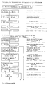
- the circuit arrangement shown in FIG. 1 is used to carry out different measuring methods, different measuring variables being determined which enable a check of protective measures in AC networks.
- the circuit contains a controlled two-way rectifier 3, one of which is to be checked with its input between phase L1 and the protective conductor PE AC network is connected. Depending on the type of measurement to be carried out, the two-pole input could also be connected between the phase and the neutral conductor.
- a controlled integrator 4 At the output of the controlled two-way rectifier 3 is a controlled integrator 4, which is followed by an A / D converter 5.
- the output signal of the A / D converter 5 and a zero detector 6 are fed to a microprocessor 7.
- the input of the zero detector 6 is connected to a voltage divider R1, R2, which connects the mains connections L1, PE to one another and at the same time also forms the input of the controlled two-way rectifier 3.
- the mains voltage reduced by the voltage divider R1, R2 is fed from its tap to a first controlled switch S1, which is located at the input of the integrator 4.
- a second controlled switch S2, also connected to the input of the integrator 4 is preceded by an inverting amplifier V1, R3, R4, the input of which lies at the tap of the voltage divider R1, R2.
- the controlled integrator 4 includes an amplifier V2, which is bridged on the input side by a third controlled switch S3, and in whose negative feedback branch there is a charging capacitor C1 to which a fourth controlled switch S4 is connected in parallel.
- a load branch is connected, which consists of the series connection of a relay switch S5, a constant current circuit 1 and a current monitor 2.
- the relay switch S5 is actuated by a relay K1, which in turn is connected to an upstream one Transistor lying control terminal a is controlled by the computer 7.
- Further control connections b to h are also connected to the computer, which queries the respective measured values via the A / D converter 5 and, after their evaluation, displays the measurement result on a display 8.
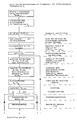
- the diagrams shown in FIG. 2 are intended to illustrate a measurement sequence as used in the measurement of the contact voltage, the internal network resistance, the loop resistance and the earth resistance.
- the voltage reduction method is used to determine these measured variables. This means that a load phase must follow an idle phase so that the mains voltage can be measured both at idle and under load. The difference between these two voltages is proportional to the measured variable sought.
- the duration of the load and idle phases is fixed to one period each.
- the constant current I K forming the load is thus interrupted after a period for the duration of a further period.
- a constant current I K is used in order to avoid load fluctuations which could falsify the measurement result.
- the diagram of the input voltage U E present at the input of the integrator 4 illustrates the mode of operation of the controlled two-way rectifier 3.
- the inverting amplifier V1, R3, R4 ensures that the mains alternating voltage present at the controlled switch S2 is 180 ° with respect to the voltage present at the controlled switch S1 is shifted in phase.
- the two controlled switches S1, S2 are now switched so that they cause rectification but in such a way that the polarity of the rectified AC voltage is reversed after one period.
- two negative half-waves follow each of two positive half-waves.
- the negative half-waves correspond to the load phase and accordingly have a somewhat lower amplitude than the positive half-waves measured during idling.
- the diagram of the output voltage U A at the output of the integrator 4 reveals its mode of operation.
- the two positive half-waves of the input voltage U E are first integrated and then integrated with the two negative half-waves. Since the amplitude of the negative half-wave due to the load is lower, a residual voltage U A remains at the integrator output, which corresponds to the difference between the load and open circuit voltage.
- the constant current I K flowing in the load phase could lead to a dangerous touch voltage if the network is faulty.
- a precise measurement of the touch voltage over several integration cycles requires a time much longer than 40 ms.
- the constant current I K can be switched off immediately in the event of danger if the contact voltage is too high a test measurement is carried out, in which the output voltage U A determined during the main measurement is compared with a predetermined limit value U BL .
- the limit value U BL corresponds to the upper limit, the still permissible touch voltage U B and must be increased after each integration cycle. Since the output voltage at integrator U A2 reaches approximately twice the value of U A1 , U BL2 must also be set to double and U BL3 to triple the value of U BL1 .
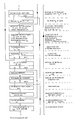
- the diagrams shown in FIG. 3 are intended to clarify the measurement sequence when checking an RCD. Its switching behavior is again examined with a constant current I K. To determine the tripping time, a constant current labeled I K , is specified, which jumps to the full value of the nominal residual current of the respective RCD after switching on. The amplitude of the constant current could reach a value I K2 which is kept constant until the FI switch responds and is only switched off after the measurement has been completed.
- the value of the current at which the RCD switches off can be determined by increasing the amplitude of the constant current from a low value I K1 continuously or in stages. As indicated by curve I K ⁇ , the constant current reaches a base value of 30% of the nominal fault current after switching on and then increases to 100%.
- the constant current circuit 1 is programmed in such a way that the constant current increases in steps of 1%, so that the cut-off current of the FI switch results directly from the step value reached when switching off.
- the step-wise increasing constant current I K is shown again in detail in FIG.
- the drawn steps indicate the increasing AC voltage amplitude of the constant current.
- the highest level of 100% corresponds to the nominal error current I ⁇ N and the related contact voltage U BN . If, as assumed in this example, the RCD switches at time t A , the tripping current I ⁇ and also the contact voltage U B present at this time can be determined via the step value of I K.
- the step value of I K is recorded by means of a run counter during the programmed step increase. In the present example it is 70%.
- the integrator 4 which is required anyway for the measurement according to FIG. 2, is not required for the measurement according to FIG. 3 explained above, so that it can be used for the test measurements required for the touch voltage measurement.
- the controlled switches S1, S2 are switched such that only the positive half-wave U E arrives at the input of the integrator 4. This voltage is integrated during the first half period and, after the output voltage value has been taken over by the computer 7, is deleted in the subsequent half period by neutralizing the integrator with the aid of the controlled switches S3, S4.
- the rough determination of the touch voltage which is to be carried out for safety reasons, is carried out in such a way that a pilot measurement is carried out first when idling and the output voltage U A1 determined in this way is stored. After switching on the constant current I K , the output voltage is measured again, whereby a value U A2 is determined. This measurement is repeated every period. The difference between the two voltages U A1 and U A2 corresponds to the respective touch voltage. If the touch voltage exceeds the permissible value, the constant current circuit 1 and the relay switch S5 are switched off.
- An important advantage of the invention is that all measurements can be carried out with the same circuit arrangement, so that no additional expenditure arises with regard to the hardware required.
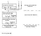
- Flow diagram 1 consisting of parts 1A and 1B, shows the determination of the tripping time of RCDs, which is carried out with the aid of a constant constant current I K.
- I K constant constant current
- the actual measurement is preceded by the pilot measurement already explained for determining the open circuit voltage of the network.
- Parts 2, 2B and 2C of flow diagram 2 explain the method used to determine the tripping current of RCDs, in which a step-wise constant current I K is used. It thus encompasses the actual core of the invention already explained with reference to FIG. 4. So that the touch voltage occurring at the time of tripping t A can be determined, the touch voltage U BN related to the nominal fault current I ⁇ N must be measured before the RCD is triggered . This measurement is carried out according to flow chart 1.
Abstract
Description
Die Erfindung betrifft ein Meßverfahren der im Oberbegriff des Anspruchs 1 genannten Art sowie eine Schaltungsanordnung zur Durchführung dieses Verfahrens.The invention relates to a measuring method of the type mentioned in the preamble of
Das Ausschaltverhalten eines Fehlerstrom-Schutzschalters wird durch seine Auslösezeit und seinen Auslösestrom bestimmt. Beide Größen ermittelt man mit Hilfe eines Prüfstroms, der zur Ermittlung der Auslösezeit seinen eingestellten Wert beibehält, während er zur Ermittlung des Auslösestroms stetig oder in Stufen ansteigen muß. Für die Beurteilung des jeweiligen Netzes, in dem der FI-Schalter für ausreichende Sicherheit sorgen soll, ist es weiterhin von Interesse, wie hoch die Berührungsspannung ist, die beim Auslösen des FI-Schalters am Schutzleiter anliegt.The breaking behavior of a residual current circuit breaker is determined by its tripping time and its tripping current. Both quantities are determined with the aid of a test current which maintains its set value for determining the tripping time, while it has to increase continuously or in stages in order to determine the tripping current. For the assessment of the respective network in which the RCD should ensure sufficient safety, it is also of interest how high the contact voltage is when the RCD is triggered on the protective conductor.
Bekannte Meßverfahren, die eine Ermittlung sowohl des Auslösestroms als auch der beim Auslösen anliegenden Berührungsspannung ermöglichen, arbeiten mit getrennten Meßeinheiten, die jede für sich eine der beiden Meßgrößen ermittelt. Hierdurch wird nicht nur die Meßapparatur relativ aufwendig, sondern auch der Meßablauf ist nicht einfach, da zwei unterschiedliche Größen zur gleichen Zeit gemessen werden müssen.Known measuring methods which enable determination of both the tripping current and the contact voltage applied when tripping work with separate measuring units, each of which determines one of the two measured variables for itself. This not only makes the measuring apparatus relatively complex, but also the measuring process is not easy, since two different sizes have to be measured at the same time.
Aus DE-B-26 58 185 ist eine Schaltungsanordnung zur Erzeugung eines Prüfstromes zwecks Prüfung von Schutzschaltern bekanntgeworden, bei welcher beim Überschreiten eines ermittelten Grenzwertes der Berührungsspannung (Spannung zwischen Schutzleiter und Erde) während des automatischen Anstieges des Prüfstromes über eine elektronische Verstärkeranordnung der Prüfstromfluß unterbrochen wird.From DE-B-26 58 185 a circuit arrangement for generating a test current for testing circuit breakers has become known, in which the test current flow is interrupted by an electronic amplifier arrangement when an established limit value of the contact voltage (voltage between protective conductor and earth) is exceeded during the automatic rise of the test current becomes.
Aus EP-A-0 165 512 (=DE-A-3 421 873) ist schließlich ein Meßverfahren zur Ermittlung der Differenz zwischen zwei Spannungen durch einen zeitgesteuerten Meßablauf, der dafür sorgt, daß in aufeinanderfolgenden fest vorgegebenen Zeitspannen zuerst die eine und dann die andere Spannung integriert wird, bekannt.Finally, from EP-A-0 165 512 (= DE-A-3 421 873) is a measuring method for determining the difference between two voltages by means of a time-controlled measuring sequence, which ensures that, in successive, predetermined periods of time, first one and then that other voltage is integrated, known.
Aus DE-A-3 421 829 geht außerdem ein Meßverfahren hervor, bei welchem die bei Fehlernennstrom des jeweiligen FI-Schalters auftretende Berührungsspannung nur einmal ermittelt wird.DE-A-3 421 829 also shows a measuring method in which the contact voltage occurring at the rated fault current of the respective RCD is determined only once.
Aufgabe der Erfindung ist es, ein Meßverfahren der im Oberbegriff des Anspruchs 1 genannten Art zu schaffen, das es ermöglicht, auf einfache Weise neben dem Auslösestrom auch die Berührungsspannung zu messen, wobei die hierzu erforderliche Schaltungsanordung mit einem zweipoligen Anschluß auskommen soll.The object of the invention is to provide a measuring method of the type mentioned in the preamble of
Diese Aufgabe wird durch die in den Ansprüchen 1 und 13 gekennzeichneten Merkmale gelöst. Zweckmäßige Ausgestaltungen und Weiterbildungen der Erfindung sind in den Unteransprüchen genannt.This object is achieved by the features characterized in
Das erfindungsgemäße Meßverfahren kommt bei einem Prüfgerät zur Anwendung, das nicht nur zur Überprüfung von FI-Schaltern dient, sondern mit dem man auch die Berührungsspannung, den Netzinnenwiderstand, den Schleifwiderstand und den Erdungswiderstand eines zu überprüfenden Wechselspannungsnetzes messen kann. Das Gerät bedarf somit keiner zusätzlichen Ausrüstung, um zu Beginn des Meßablaufs die Berührungsspannung zu ermitteln. Zu beachten ist, daß die Berührungsspannung nicht bei Fehlernennstrom gemessen werden darf, da andernfalls der Strom zu einem Auslösen des FI-Schalters führen würde, bevor seine eigentliche Prüfung beginnt. Es hat sich als zweckmäßig erwiesen, die Berührungsspannung bei einem Drittel des Fehlernennstroms zu messen und die gesuchte auf den Fehlernennstrom bezogene Berührungsspannung entsprechend hochzurechnen.The measuring method according to the invention is used in a test device which is not only used to check RCDs, but which can also be used to measure the contact voltage, the internal network resistance, the grinding resistance and the earth resistance of an AC network to be checked. The device therefore does not require any additional equipment to determine the touch voltage at the start of the measurement process. It should be noted that the touch voltage must not be measured at the rated fault current, otherwise the current would trigger the RCD before its actual test begins. It has proven to be expedient to measure the touch voltage at a third of the nominal fault current and to extrapolate the contact voltage sought based on the nominal fault current accordingly.
Sobald die auf den Fehlernennstrom bezogene Berührungsspannung gespeichert ist, kann die eigentliche Prüfung des FI-Schalters mit Hilfe eines in Stufen ansteigenden Konstantstroms beginnen. Hat der Konstantstrom eine Höhe erreicht, bei der der FI-Schalter auslöst, so ergibt sich der Auslösestrom unmittelbar aus dem Stufenwert des Konstantstroms. Da der Stufenendwert des Konstantstroms dem Fehlernennstrom entspricht und die auf den Fehlernennstrom bezogene Berührungsspannung bekannt ist, kann auch die im Auslösezeitpunkt auftretende Berührungsspannung vom Rechner des Meßgerätes ermittelt und zur Anzeige ausgegeben werden.As soon as the contact voltage related to the nominal fault current has been saved, the actual test of the RCD can begin with the help of a constant current that increases in stages. The constant current has a height reached at which the RCD triggers, the tripping current results directly from the step value of the constant current. Since the final stage value of the constant current corresponds to the nominal fault current and the contact voltage related to the nominal nominal current is known, the contact voltage occurring at the time of tripping can also be determined by the computer of the measuring device and output for display.
In einer zweckmäßigen Ausgestaltung der Erfindung ist vorgesehen, den Konstantstrom von einem Basiswert von 0,3 des Nennfehlerstroms bis zum Nennfehlerstrom ansteigen zu lassen. Man kann davon ausgehen, daß der Auslösestrom des FI-Schalters im Normalfall in diesem Bereich liegen wird.In an expedient embodiment of the invention, it is provided that the constant current rise from a base value of 0.3 of the nominal fault current to the nominal fault current. It can be assumed that the tripping current of the RCD will normally be in this range.
Eine ausreichende Genauigkeit der Messung wird erzielt, wenn man den Konstantstrom in Stufen von 1 % des Nennfehlerstroms ansteigen läßt. Eine Stufenlänge von 40 ms reicht im allgemeinen aus, damit der FI-Schalter den Strom als Konstantstrom empfindet und die Dynamik der Stufen nicht in Erscheinung tritt.Sufficient accuracy of the measurement is achieved if the constant current is increased in steps of 1% of the nominal residual current. A step length of 40 ms is generally sufficient so that the RCD switches perceive the current as a constant current and the dynamics of the steps do not appear.
In einer zweckmäßigen Weiterbildung des erfindungsgemäßen Verfahrens wird die Berührungsspannung nach der Methode der Spannungsabsenkung gemessen. Diese Methode ist in der EP-A-0 165 512 (=DE-A-34 21 873) in Verbindung mit einer Auf-Ab-Integration beschrieben. Die Messung erstreckt sich über mehrere Perioden, wobei jeweils auf eine Leerlaufperiode eine Lastperiode folgt, bei der das Netz mit einem Prüfstrom belastet wird. Die Differenz zwischen der gemessenen Leerlaufspannung und der Lastspannung entspricht der zu ermittelnden Berührungsspannung, sofern zwischen dem L- und dem PE-Leiter des Netzes gemessen wird. Bei dem vorbekannten Verfahren wird die Differenzspannung auf besonders einfache Weise dadurch erfaßt, daß zwei gleichgerichtete Halbwellen der Leerlaufspannung aufintegriert und bei Last zwei folgende gleichgerichtete Halbwellen abintegriert werden. Die im Integrator verbleibende Restspannung entspricht dabei der gesuchten Differenzspannung, die die Berührungsspannung repräsentiert.In an expedient development of the method according to the invention, the touch voltage is measured using the voltage reduction method. This method is described in EP-A-0 165 512 (= DE-A-34 21 873) in connection with an up-down integration. The measurement extends over several periods, with an idle period being followed by a load period in which the network is loaded with a test current. The difference between the measured open circuit voltage and the load voltage corresponds to the touch voltage to be determined, provided that it is between the L and the PE conductor of the network is measured. In the previously known method, the differential voltage is detected in a particularly simple manner by integrating two rectified half-waves of the open circuit voltage and integrating two subsequent rectified half-waves under load. The residual voltage remaining in the integrator corresponds to the differential voltage sought, which represents the touch voltage.
Um eine von Spannungsschwankungen weitgehend unbeeinflußte, möglichst genaue Messung zu ermöglichen, wird der aus einer Auf-Ab-Integration bestehende Integrationszyklus mehrfach wiederholt, so daß sich die Messung insgesamt über eine Vielzahl von Perioden erstreckt. Der während dieser Zeit über den Schutzleiter PE fließende Prüfstrom kann in fehlerhaften Netzen zu unzulässigen Berührungsspannungen führen.In order to enable a measurement that is largely unaffected by voltage fluctuations and is as accurate as possible, the integration cycle consisting of an up-down integration is repeated several times, so that the measurement extends over a large number of periods. The test current flowing through the protective conductor PE during this time can lead to impermissible contact voltages in faulty networks.
Die von zu hohen Berührungsspannungen ausgehende Gefahr ist um so geringer, je kürzer die Spannung am Schutzleiter anliegt. Nach VDE ist diese Zeit auf max. 200 ms zu begrenzen, während die KEMA empfiehlt eine Zeit von 40 ms nicht zu überschreiten.The risk of contact voltages being too high is lower the shorter the voltage is applied to the protective conductor. According to VDE, this time is limited to max. Limit 200 ms, while KEMA recommends not to exceed a time of 40 ms.
Eine wesentliche Weiterbildung des erfindungsgemäßen Verfahrens wird deshalb darin gesehen, den Verfahrensablauf so zu gestalten, daß beim Auftreten gefährlicher Berührungsspannungen diese nicht über einen Zeitraum von 40 ms hinaus am Schutzleiter anstehen können. Hierzu wird die nach jedem Integrationszyklus ermittelte Ausgangsspannung mit einem Limitwert verglichen, der dem Grenzwert der noch zulässigen Berührungsspannung entspricht. Eine Unterbrechung des Konstantstroms erfolgt, sobald die Ausgangsspannung größer als der Limitwert ist. Parallel zu der sich über mehrere Integrationszyklen erstreckenden Hauptmessung erfolgt also nach jedem Integrationszyklus eine Testmessung, die bei einer überhöhten Berührungsspannung innerhalb von 40 ms ein Abschalten des Prüfstroms bewirkt. Da die Ausgangsspannung am Integrator nach jedem Integrationszyklus ansteigt, muß auch der Limitwert entsprechend erhöht werden.An essential further development of the method according to the invention is therefore seen in designing the process sequence in such a way that when dangerous contact voltages occur, they cannot be present on the protective conductor for a period of more than 40 ms. For this purpose, the output voltage determined after each integration cycle is compared with a limit value that corresponds to the limit value of the contact voltage that is still permissible. The constant current is interrupted as soon as the output voltage is greater than the limit value is. In parallel to the main measurement, which extends over several integration cycles, a test measurement is carried out after each integration cycle, which causes the test current to be switched off within 40 ms if the contact voltage is excessive. Since the output voltage at the integrator increases after each integration cycle, the limit value must also be increased accordingly.
Eine besonders einfache Methode zur Abschaltung des Konstantstroms besteht darin, diesen bei jeder Halbwelle neu einzuschalten und den hierfür erforderlichen Einschaltimpuls zur Bewirkung der Abschaltung zu unterdrücken.A particularly simple method for switching off the constant current is to switch it on again every half-wave and to suppress the switch-on pulse required for this to effect the switch-off.
Eine zweckmäßige Weiterbildung der Erfindung sieht weiterhin vor, in Verbindung mit der Hauptmessung zur Überprufüng von FI-Schaltern zunächst eine Pilotmessung durchzuführen, bei der die Netzspannung im Leerlauf erfaßt wird. Dieser Spannungswert wird gespeichert und dient als Referenzwert für sich anschließende Spannungsmessungen unter Belastung mit einem vorgegebenen Konstantstrom. Letztere dienen als Testmessungen, die jeweils in der ersten Halbwelle einer Periode durchgeführt und in der zweiten Halbwelle ausgewertet werden. Auch hier kann also bei überhöhter Berührungsspannung bereits nach einer Periode ein Abschaltbefehl gegeben werden. Die jeweilige Berührungsspannung ergibt sich aus der Differenz zwischen dem gespeicherten Referenzwert und dem jeweiligen momentanen Testwert.An expedient development of the invention further provides, in connection with the main measurement for checking RCDs, first of all to carry out a pilot measurement in which the mains voltage is detected in no-load operation. This voltage value is saved and serves as a reference value for subsequent voltage measurements under load with a predetermined constant current. The latter serve as test measurements, which are each carried out in the first half-wave of a period and evaluated in the second half-wave. In this case, too, a switch-off command can be given after a period if the contact voltage is excessive. The respective touch voltage results from the difference between the stored reference value and the respective current test value.
Für die Durchführung der Messung ist wichtig, daß der Konstantstrom programmierbar ist und damit in seinem Wert automatisch geändert werden kann. So werden je nach Art der Hauptmessung unterschiedliche Konstantströme benötigt. Bei den Hauptmessungen nach der Spannungsabsenkungsmethode wird der Konstantstrom vorzugsweise auf 30 % des Nennfehlerstroms im Netz liegender FI-Schalter programmiert, damit die Messung durchgeführt werden kann, ohne daß der FI-Schalter abschaltet.To carry out the measurement it is important that the constant current is programmable and its value can be changed automatically. So depending on Different constant currents are required for the type of main measurement. For the main measurements using the voltage reduction method, the constant current is preferably programmed to 30% of the nominal residual current in the residual current circuit breaker so that the measurement can be carried out without the FI switch being switched off.
Eine zu hohe Berührungsspannung wird gegebenenfalls vorgetäuscht, wenn z.B. der FI-Schalter im Laufe der Messung abgeschaltet hat aber zum Zeitpunkt der Pilotmessung noch eingeschaltet war, so daß die Differenzspannung dem Wert der Referenzspannung entspricht. Um diesen Fall auszuschließen, wird vor der Meldung einer gefährlichen Berührungsspannung noch das Anliegen der Netzspannung geprüft.Too high a touch voltage may be simulated if e.g. the FI switch was switched off during the measurement but was still switched on at the time of the pilot measurement, so that the differential voltage corresponds to the value of the reference voltage. In order to rule out this case, the presence of the mains voltage is checked before a dangerous touch voltage is reported.
Weiterhin ist es möglich, daß der FI-Schalter bei seiner Überprufüng mit dem Nennfehlerstrom nicht innerhalb der vorgeschriebenen Zeit abgeschaltet hat. Eine Fehlermeldung erfolgt jedoch erst dann, wenn feststeht, daß in der letzten Periode des Prüfablaufs der Konstantstrom noch fließt. Nach Ablauf der automatischen Messung wird nämlich auch ohne daß der FI-Schalter den Stromkreis unterbricht der Konstantstrom abgeschaltet.Furthermore, it is possible that the RCD did not switch off within the specified time when it was checked with the nominal residual current. However, an error message is only issued when it is certain that the constant current is still flowing in the last period of the test sequence. After the automatic measurement has expired, the constant current is switched off even without the FI switch interrupting the circuit.
Für die vorgesehene Sicherheitsabschaltung durch Unterbrechung des Konstantstroms ist der Lastzweig von besonderer Bedeutung. Er beinhaltet zwei in Reihe liegende Glieder, die beide ein Abschalten des Konstantstroms ermöglichen. So wird, wie bereits erläutert, bei zu hoher Berührungsspannung der Einschaltimpuls, der die nächste Halbwelle des Konstantstroms auslöst, unterdrückt, so daß die Konstantstromschaltung keinen Strom mehr abgibt. Gleichzeitig wird jedoch auch das Relais betätigt das den Stromkreis noch während der anstehenden Halbwelle unterbricht. Das Relais wirkt somit schneller und besitzt auch ein höheres Abschaltvermögen. Mit Hilfe der Stromüberwachung läßt sich eine Unterbrechung des Stromkreises auf einfache Weise verifizieren.The load branch is of particular importance for the intended safety shutdown by interrupting the constant current. It contains two elements in series, both of which enable the constant current to be switched off. Thus, as already explained, if the contact voltage is too high, the switch-on pulse which triggers the next half-wave of the constant current is suppressed, so that the constant current circuit no longer delivers current. At the same time, however, the relay also actuates that the circuit is still interrupted during the upcoming half-wave. The relay thus works faster and also has a higher breaking capacity. With the help of current monitoring, an interruption in the circuit can be verified in a simple manner.
Ein Ausführungsbeispiel der Erfindung ist in den Zeichnungen dargestellt und wird im folgenden näher beschrieben.An embodiment of the invention is shown in the drawings and will be described in more detail below.
Es zeigen:
- Figur 1:
- Eine Schaltungsanordnung zur Durchführung des erfindungsgemäßen Verfahrens,
- Figur 2:
- Strom- und Spannungsdiagramme über mehrere Perioden des Meßablaufs bei einer Messung nach der Spannungsabsenkungsmethode,
- Figur 3:
- Strom- und Spannungsdiagramme über mehrere Perioden eines Meßablaufs zur Prüfung des Ausschaltverhaltens eines FI-Schalters,
- Figur 4:
- Verlauf des stufig ansteigenden Konstantstroms zur Ermittlung des Auslösestroms und der zugehörigen Berührungsspannung.
- Figure 1:
- A circuit arrangement for carrying out the method according to the invention,
- Figure 2:
- Current and voltage diagrams over several periods of the measurement sequence for a measurement using the voltage reduction method,
- Figure 3:
- Current and voltage diagrams over several periods of a measurement sequence to test the switch-off behavior of an RCD,
- Figure 4:
- Course of the steadily increasing constant current to determine the tripping current and the associated touch voltage.
Die in Figur 1 dargestellte Schaltungsanordnung dient zur Durchführung verschiedener Meßverfahren, wobei unterschiedliche Meßgrößen ermittelt werden, die eine Überprüfung von Schutzmaßnahmen in Wechselstromnetzen ermöglichen. Die Schaltung enthält einen gesteuerten Zweiweggleichrichter 3, der mit seinem Eingang zwischen Phase L1 und dem Schutzleiter PE eines zu überprüfenden Wechselspannungsnetzes angeschlossen ist. Je nach Art der durchzuführenden Messung könnte der zweipolige Eingang auch zwischen Phase und Null-Leiter angeschlossen sein. Am Ausgang des gesteuerten Zweiweggleichrichters 3 liegt ein gesteuerter Integrator 4, dem ein A/D-Wandler 5 nachgeschaltet ist. Einem Mikroprozessor 7 wird das Ausgangssignal des A/D-Wandlers 5 sowie eines Null-Detektors 6 zugeführt. Der Null-Detektor 6 liegt mit seinem Eingang an einem Spannungsteiler R1, R2, der die Netzanschlüsse L1, PE miteinander verbindet und gleichzeitig auch den Eingang des gesteuerten Zweiweggleichrichters 3 bildet.The circuit arrangement shown in FIG. 1 is used to carry out different measuring methods, different measuring variables being determined which enable a check of protective measures in AC networks. The circuit contains a controlled two-
Die vom Spannungsteiler R1, R2 herabgesetzte Netzspannung wird von seinem Abgriff einem ersten gesteuerten Schalter S1 zugeführt, der am Eingang des Integrators 4 liegt. Einem zweiten ebenfalls mit dem Eingang des Integrators 4 verbundenen gesteuerten Schalter S2 ist ein invertierender Verstärker V1,R3,R4 vorgeschaltet, dessen Eingang an dem Abgriff des Spannungsteilers R1, R2 liegt.The mains voltage reduced by the voltage divider R1, R2 is fed from its tap to a first controlled switch S1, which is located at the input of the integrator 4. A second controlled switch S2, also connected to the input of the integrator 4, is preceded by an inverting amplifier V1, R3, R4, the input of which lies at the tap of the voltage divider R1, R2.
Zu dem gesteuerten Integrator 4 gehören ein Verstärker V2, der eingangsseitig von einem dritten gesteuerten Schalter S3 überbrückt ist, und in dessen Gegenkopplungszweig ein Ladekondensator C1 liegt, dem ein vierter gesteuerter Schalter S4 parallel geschaltet ist.The controlled integrator 4 includes an amplifier V2, which is bridged on the input side by a third controlled switch S3, and in whose negative feedback branch there is a charging capacitor C1 to which a fourth controlled switch S4 is connected in parallel.
Am Eingang der Schaltungsanordnung zwischen Phase L1 und Schutzleiter PE ist ein Lastzweig angeschlossen, der aus der Reihenschaltung eines Relaisschalters S5, einer Konstantstromschaltung 1 und einer Stromüberwachung 2 besteht. Der Relaisschalter S5 wird über ein Relais K1 betätigt, das seinerseits über den an einem vorgeschalteten Transistor liegenden Steueranschluß a vom Rechner 7 gesteuert wird. Weitere Steueranschlüsse b bis h sind ebenfalls mit dem Rechner verbunden, der über den A/D-Wandler 5 die jeweiligen Meßwerte abfragt und nach ihrer Auswertung das Meßergebnis auf einem Display 8 zur Anzeige bringt.At the input of the circuit arrangement between phase L1 and protective conductor PE, a load branch is connected, which consists of the series connection of a relay switch S5, a constant
Die in Figur 2 dargestellten Diagramme sollen einen Meßablauf verdeutlichen, wie er bei der Messung der Berührungsspannung, des Netzinnenwiderstandes, des Schleifenwiderstandes und des Erdungswiderstandes zur Anwendung kommt. Bei der Ermittlung dieser Meßgrößen wird nach der Methode der Spannungsabsenkung verfahren. Das bedeutet, daß auf eine Leerlaufphase eine Lastphase folgen muß, so daß die Netzspannung sowohl im Leerlauf als auch unter Last gemessen werden kann. Der Differenzwert dieser beiden Spannungen ist der gesuchten Meßgröße proportional. Im vorliegenden Fall ist die Dauer der Last- und der Leerlaufphase auf jeweils eine Periode festgelegt. Der die Last bildende Konstantstrom IK wird somit nach einer Periode jeweils für die Dauer einer weiteren Periode unterbrochen. Es wird mit einem Konstantstrom IK gearbeitet, um Lastschwankungen, die das Meßergebnis verfälschen könnten, zu vermeiden.The diagrams shown in FIG. 2 are intended to illustrate a measurement sequence as used in the measurement of the contact voltage, the internal network resistance, the loop resistance and the earth resistance. The voltage reduction method is used to determine these measured variables. This means that a load phase must follow an idle phase so that the mains voltage can be measured both at idle and under load. The difference between these two voltages is proportional to the measured variable sought. In the present case, the duration of the load and idle phases is fixed to one period each. The constant current I K forming the load is thus interrupted after a period for the duration of a further period. A constant current I K is used in order to avoid load fluctuations which could falsify the measurement result.
Das Diagramm der am Eingang des Integrators 4 anliegenden Eingangsspannung UE verdeutlicht die Wirkungsweise des gesteuerten Zweiweggleichrichters 3. Der invertierende Verstärker V1, R3,R4 sorgt dafür, daß die am gesteuerten Schalter S2 anliegende Netzwechselspannung um 180° gegenüber der am gesteuerten Schalter S1 anliegenden Spannung in der Phase verschoben wird. Die beiden gesteuerten Schalter S1,S2 werden nun so geschaltet, daß sie eine Gleichrichtung bewirken aber derart, daß sich die Polarität der gleichgerichteten Wechselspannung nach jeweils einer Periode umkehrt. Somit folgen jeweils auf zwei positive Halbwellen zwei negative Halbwellen. Die negativen Halbwellen entsprechen der Lastphase und besitzten dementsprechend eine etwas geringere Amplitude als die im Leerlauf gemessenen positiven Halbwellen.The diagram of the input voltage U E present at the input of the integrator 4 illustrates the mode of operation of the controlled two-
Das Diagramm der Ausgangsspannung UA am Ausgang des Integrators 4 läßt dessen Wirkungsweise erkennen. Die beiden positiven Halbwellen der Eingangsspannung UE werden zunächst aufintegriert und anschließend mit den beiden negativen Halbwellen abintegriert. Da die Amplitude der negativen Halbwelle durch die Belastung geringer ist, verbleibt am Integratorausgang eine Restspannung UA, die der Differenz zwischen Last- und Leerlaufspannung entspricht.The diagram of the output voltage U A at the output of the integrator 4 reveals its mode of operation. The two positive half-waves of the input voltage U E are first integrated and then integrated with the two negative half-waves. Since the amplitude of the negative half-wave due to the load is lower, a residual voltage U A remains at the integrator output, which corresponds to the difference between the load and open circuit voltage.
Um die verbleibende Restspannung zu erhöhen und damit die Meßgenauigkeit zu verbessern, folgen jeweils mehrere Integrationszyklen aufeinander, wobei jeder Integrationszyklus sich über zwei Perioden erstreckt. Die nach dem letzten Integrationszyklus am Ausgang des Integrators 4 verbleibende Ausgangsspannung wird mit Hilfe des Rechners durch die Zahl der Integrationszyklen geteilt und ergibt danach einen Mittelwert, in dem Schwankungen einzelner Perioden weitgehend eliminiert sind.In order to increase the remaining residual voltage and thus to improve the measurement accuracy, several integration cycles follow one another, each integration cycle extending over two periods. The output voltage remaining at the output of the integrator 4 after the last integration cycle is divided with the aid of the computer by the number of integration cycles and then gives an average value in which fluctuations in individual periods are largely eliminated.
Der in der Lastphase fließende Konstantstrom IK könnte bei fehlerhaftem Netz zu einer gefährlichen Berührungsspannung führen. Eine genaue Messung der Berührungsspannung über mehrere Integrationszyklen erfordert eine weit längere Zeit als 40 ms. Damit im Gefahrenfall bei zu hoher Berührungsspannung der Konstantstrom IK sofort abgeschaltet werden kann, wird nach jedem Integrationszyklus eine Testmessung vorgenommen, bei der die während der Hauptmessung ermittelte Ausgangsspannung UA mit einem vorgegebenen Limitwert UBL verglichen wird. Der Limitwert UBL entspricht der oberen Grenze, der noch zulässigen Berührungsspannung UB und muß nach jedem Integrationszyklus erhöht werden. Da die Ausgangsspannung am Integrator UA2 etwa den doppelten Wert von UA1 erreicht, muß auch UBL2 auf den doppelten und UBL3 auf den dreifachen Wert von UBL1 festgelegt werden.The constant current I K flowing in the load phase could lead to a dangerous touch voltage if the network is faulty. A precise measurement of the touch voltage over several integration cycles requires a time much longer than 40 ms. After an integration cycle, the constant current I K can be switched off immediately in the event of danger if the contact voltage is too high a test measurement is carried out, in which the output voltage U A determined during the main measurement is compared with a predetermined limit value U BL . The limit value U BL corresponds to the upper limit, the still permissible touch voltage U B and must be increased after each integration cycle. Since the output voltage at integrator U A2 reaches approximately twice the value of U A1 , U BL2 must also be set to double and U BL3 to triple the value of U BL1 .
Die in Figur 3 dargestellten Diagramme sollen den Meßablauf bei der Überprüfung eines FI-Schalters verdeutlichen. Sein Schaltverhalten wird wiederum mit einem Konstantstrom IK untersucht. Zur Ermittlung der Auslösezeit wird ein mit IK, gekennzeichneter Konstantstrom vorgegeben, der nach dem Einschalten auf den vollen Wert des Nennfehlerstroms des jeweilen FI-Schalters springt. Die Amplitude des Konstanstroms könnte einen Wert IK2 erreichen, der bis zum Ansprechen des FI-Schalters konstant gehalten und erst nach Abschluß der Messung abgeschaltet wird.The diagrams shown in FIG. 3 are intended to clarify the measurement sequence when checking an RCD. Its switching behavior is again examined with a constant current I K. To determine the tripping time, a constant current labeled I K , is specified, which jumps to the full value of the nominal residual current of the respective RCD after switching on. The amplitude of the constant current could reach a value I K2 which is kept constant until the FI switch responds and is only switched off after the measurement has been completed.
Den Wert des Stroms, bei dem der FI-Schalter abschaltet, kann man ermitteln, indem man die Amplitude des Konstantstroms von einem niedrigen Wert IK1 stetig oder stufig erhöht. Wie durch die Kurve IK˝ angedeutet ist, erreicht der Konstantstrom nach dem Einschalten einen Basiswert von 30 % des Fehlernennstroms und steigt dann bis 100 % an. Die Konstantstromschaltung 1 ist so programmiert, daß der Konstantstrom in Stufen von 1 % ansteigt, so daß sich unmittelbar aus dem beim Abschalten erreichten Stufenwert der Abschaltstrom des FI-Schalters ergibt.The value of the current at which the RCD switches off can be determined by increasing the amplitude of the constant current from a low value I K1 continuously or in stages. As indicated by curve I K˝ , the constant current reaches a base value of 30% of the nominal fault current after switching on and then increases to 100%. The constant
In Figur 4 ist der stufig ansteigende Konstantstrom IK noch einmal im Detail dargestellt. Die gezeichneten Stufen kennzeichnen die steigende Wechselspannungsamplitude des Konstantstroms. Die höchste Stufe von 100 % entspricht dem Fehlernennstrom IΔN sowie der hierauf bezogenen Berührungsspannung UBN. Wenn nun, wie in diesem Beispiel angenommen, der FI-Schalter zum Zeitpunkt tA auslöst, kann über den Stufenwert von IK der Auslösestrom IΔ und auch die zu diesem Zeitpunkt anliegende Berührungsspannung UB festgestellt werden. Der Stufenwert von IK wird mittels eines Durchlaufzählers während des programmierten Stufenanstiegs erfaßt. Im vorliegenden Beispiel liegt er bei 70 %.The step-wise increasing constant current I K is shown again in detail in FIG. The drawn steps indicate the increasing AC voltage amplitude of the constant current. The highest level of 100% corresponds to the nominal error current I ΔN and the related contact voltage U BN . If, as assumed in this example, the RCD switches at time t A , the tripping current I Δ and also the contact voltage U B present at this time can be determined via the step value of I K. The step value of I K is recorded by means of a run counter during the programmed step increase. In the present example it is 70%.
Der für die Messung nach Figur 2 ohnehin erforderliche Integrator 4 wird für die vorstehend erläuterte Messung nach Figur 3 nicht benötigt, so daß er für die zur Berührungsspannungsmessung erforderlichen Testmessungen herangezogen werden kann. Wie das Diagramm in Figur 3 erkennen läßt, werden die gesteuerten Schalter S1,S2 so geschaltet, daß jeweils nur die positive Halbwelle UE an den Eingang des Integrators 4 gelangt. Diese Spannung wird während der ersten halben Periode aufintegriert und nach Übernahme des Ausgangsspannungswertes durch den Rechner 7 in der sich anschließenden halben Periode durch Neutralisieren des Integrators mit Hilfe der gesteuerten Schalter S3,S4, gelöscht.The integrator 4, which is required anyway for the measurement according to FIG. 2, is not required for the measurement according to FIG. 3 explained above, so that it can be used for the test measurements required for the touch voltage measurement. As can be seen from the diagram in FIG. 3, the controlled switches S1, S2 are switched such that only the positive half-wave U E arrives at the input of the integrator 4. This voltage is integrated during the first half period and, after the output voltage value has been taken over by the computer 7, is deleted in the subsequent half period by neutralizing the integrator with the aid of the controlled switches S3, S4.
Die aus Sicherheitsgründen durchzuführende grobe Bestimmung der Berührungsspannung erfolgt derart, daß zunächst bei Leerlauf eine Pilotmessung durchgeführt wird und die hierbei ermittelte Ausgangsspannung UA1 gespeichert wird. Nach Einschalten des Konstantstroms IK erfolgt eine erneute Messung der Ausgangsspannung, wobei ein Wert UA2 ermittelt wird. Diese Messung wird in jeder Periode wiederholt. Die Differenz der beiden Spannungen UA1 und UA2 entspricht der jeweiligen Berührungsspannung. Überschreitet die Berührungsspannung den zulässigen Wert, so werden die Konstantstromschaltung 1 und auch der Relaisschalter S5 abgeschaltet.The rough determination of the touch voltage, which is to be carried out for safety reasons, is carried out in such a way that a pilot measurement is carried out first when idling and the output voltage U A1 determined in this way is stored. After switching on the constant current I K , the output voltage is measured again, whereby a value U A2 is determined. This measurement is repeated every period. The difference between the two voltages U A1 and U A2 corresponds to the respective touch voltage. If the touch voltage exceeds the permissible value, the constant
Ein wesentlicher Vorteil der Erfindung ist, daß alle Messungen mit der gleichen Schaltungsanordnung durchgeführt werden können, so daß bezüglich der erforderlichen Hardware kein Zusatzaufwand entsteht.An important advantage of the invention is that all measurements can be carried out with the same circuit arrangement, so that no additional expenditure arises with regard to the hardware required.
Die wichtigsten Schritte der vorstehend in ihrem Grundprinzip erläuterten Meßverfahren sind in zwei Ablaufdiagrammen registriert. So zeigt das aus den Teilen 1A und 1B bestehende Ablaufdiagramm 1 die Ermittlung der Auslösezeit von FI-Schaltern, die mit Hilfe eines gleichbleibenden Konstantstroms IK erfolgt. Hier wird der eigentlichen Messung die schon erläuterte Pilotmessung zur Ermittlung der Leerlaufspannung des Netzes vorangestellt.The most important steps of the measuring methods explained above in their basic principle are registered in two flow diagrams. Flow diagram 1, consisting of parts 1A and 1B, shows the determination of the tripping time of RCDs, which is carried out with the aid of a constant constant current I K. Here the actual measurement is preceded by the pilot measurement already explained for determining the open circuit voltage of the network.
Das Ablaufdiagramm 2 erläutert mit seinen Teilen 2, 2B und 2C das zur Ermittlung des Auslösestroms von FI-Schaltern angewandte Verfahren, bei dem mit einem stufig steigenden Konstantstrom IK gearbeitet wird. Es umfaßt somit den eigentlichen an Hand der Figur 4 bereits erläuterten Kern der Erfindung. Damit die im Auslösezeitpunkt tA auftretende Berührungsspannung ermittelt werden kann, muß vor dem Auslösen des FI-Schalters die auf den Nennfehlerstrom IΔN bezogene Berührungsspannung UBN gemessen werden. Diese Messung erfolgt entsprechend dem Ablaufdiagramm 1.
Im Rahmen der Testmessungen, die bei erhöhter Berührungsspannung ein Abschalten des Konstantstroms IK bewirken sollen, muß dem eigentlichen Meßablauf weiterhin eine Pilotmessung vorangestellt werden, wie sie bereits aus dem Ablaufdiagram 1 bekannt ist. Erst jetzt kann die Konstantstromschaltung für den Anstieg von IK programmiert und der Durchlaufzähler entsprechend eingestellt werden.As part of the test measurements, which are intended to switch off the constant current I K at an increased contact voltage, the actual measuring sequence must be preceded by a pilot measurement, as is already known from the flow diagram 1. Only now can the constant current circuit be programmed for the increase in I K and the flow counter set accordingly.
Claims (15)
- Measuring method for determining the trip current (IΔ) of residual-current breakers in AC networks with the aid of an increasing test current and for determining the contact voltage (UB) when the residual-current breaker is tripped, characterised by the following sequence of steps:a) firstly the contact voltage (UB) which occurs with the nominal residual current (IΔN) of the respective residual-current breaker is determined with a constant current (IK) which is smaller than the possible trip current (IΔ) of the residual-current breaker, the determination being carried out repeatedly and the value determined after each measurement being compared with a limit value which represents the limit value of the permissible contact voltage (UB);b) the contact voltage (UBN) determined with reference to the nominal residual current (IN) is stored;c) after storage according to step b), the increasing test current is produced by a constant current which increases steadily by a predetermined value at predetermined time intervals;d) the constant current (IK) at the time when the residual-current breaker is tripped, which corresponds to the trip current (IΔ), is displayed;e) the contact voltage (UB) which occurs with the trip current (IΔ) is calculated from the relationship
 f) the constant current (IK) is switched off within 40 msec after each storage of the contact voltage when there is an excessive increase in the contact voltage relative to the limit value (UBL).
 - Measuring method according to Claim 1, characterised in that the constant current (IK) increases from a base value of 0.3 of the nominal residual current (IΔN) up to the nominal residual current.
- Measuring method according to Claim 1, characterised in that the steps of the increasing constant current (IK) correspond to an AC amplitude of 0.01 of the nominal residual current (IΔN) and follow each other at time intervals of 40 ms.
- Measuring method according to any one of the preceding claims, characterised in that the determination of the contact voltage takes place according to the voltage-drop method, wherein the rectified network voltage is integrated upwards over a period in open circuit and is integrated downwards over a subsequent period with a predetermined load given by a constant current (IK), and the output voltage remaining at the output of the integrator (4) after the end of this integration cycle is proportional to the contact voltage.
- Measuring method according to any one of the preceding claims, characterised in that the output voltage (UA) in the integrator (4) is compared with a limit value (UBL) which represents the limit value of the permissible contact voltage (UB) and the contact current (IK) is interrupted if the output voltage (UA) is greater than the limit value (UBL).
- Measuring method according to any one of the preceding claims, characterised in that a first limit value (UBL1) which is given in connection with a first output voltage (UA1) in the first integration cycle is doubled to a second limit value (UBL2) in the second integration cycle with a second output voltage (UA2) and is trebled in the third integration cycle, so that, after n integration cycles, the limit value


- Measuring method according to any one of the preceding claims, characterised in that each time zero crossing is reached, the constant current (IK) is switched on again for the duration of one half wave and an interruption of the constant current (IK) takes place by the suppression of the switching pulses.
- Measuring method according to any one of the preceding claims, characterised in that, in a test of the switching-off behaviour of residual-current breakers, a pilot measurement is carried out to acquire the network voltage in open circuit and the open-circuit voltage (UA1) integrated for this over one half wave is stored, and in that the pilot measurement is followed by further measurements of the network voltage during loading, from this point on, with a constant current (IK), the network voltage being integrated again over each half wave and the load voltage (UA2) measured in each half wave being compared with the open-circuit voltage (UA1) stored.
- Measuring method according to any one of the preceding claims, characterised in that the value of the constant current (IK) is programmable and the constant current is switched on again with each half wave until it is stopped by a safety interruption or after the end of the test of a residual-current breaker, and the safety interruption takes place as soon as the voltage difference between the open-circuit voltage (UA1) and the load voltage (UA2) exceeds the permissible value of the contact voltage (UB).
- Measuring method according to any one of the preceding claims, characterised in that a first half wave of the constant current (IK), during which the integration to determine the load voltage (UA2) takes place, is followed by an evaluation phase for determining the voltage difference and evaluating it in relation to the permissible contact voltage (UB) and the integrator output voltage (UA) is neutralised during each evaluation phase, which lasts for one half wave.
- Measuring method according to any one of the preceding claims, characterised in that, in the event of the permissible contact voltage (UB) being exceeded by the voltage difference (UA1 - UA2) determined, the value, which is consequently dangerous, is indicated only when a test has revealed that the network voltage is still connected.
- Measuring method according to any one of the preceding claims, characterised in that, in order to clarify whether the residual-current breaker has not switched off within the prescribed time after a test has been carried out with the predetermined constant current (IK) and a fault indication should thus result, it is first determined whether a constant current (IK) is still flowing.
- Circuit for determining the trip current of residual-current breakers in AC networks, with a device for determining a contact voltage and a device for supplying a constant current (IK) as a controllable load, characterised in that a controlled full-wave rectifier is connected to two network voltage connections (L1, PE) and supplies a rectified alternating voltage (UE) to the input of an integrator (4), the output voltage (UA) of which is connected to an A/D convertor (5) and, moreover, a computer (7) processes the output signal of the A/D convertor (5) and, in dependence thereon and on the output signal of a zero detector (6), controls the integrator (4), the full-wave rectifier (3), and a load branch (S5, 1, 2) synchronised with the network, a device being provided for repeating at least once the integration and evaluation in relation to the output signal of the A/D convertor carried out by the computer (7) and the load branch (S5, 1, 2) connected to the two network connections (L1, PE) consisting of a switch (S5) controlled by the computer (7) by means of a relay (K1), a programmable constant current circuit (1) and a current monitor (2) connected in series.
- Circuit according to Claim 13, characterised in that the full-wave rectifier (3) comprises two controllable switches (S1, S2) which are connected to its input and of which the first switch (S1) is connected directly to the tap of a voltage divider (R1, R2) connected to the network connections (L1, PE) whilst the second switch (S2) is connected to the tap by means of an inverting amplifier (V1, R3, R4).
- Circuit according to any one of Claims 13 and 14, characterised in that the integrator (4) comprises third and fourth controllable switches (S3, S4), the input of the third switch (S3) being able to be short-circuited to a reference potential (PE) and the fourth switch (S4) bypassing its charging capacitor (C1).
Applications Claiming Priority (2)
| Application Number | Priority Date | Filing Date | Title |
|---|---|---|---|
| DE3835677A DE3835677C2 (en) | 1988-10-20 | 1988-10-20 | Measuring method and circuit arrangement for determining the tripping current of RCDs |
| DE3835677 | 1988-10-20 |
Publications (2)
| Publication Number | Publication Date |
|---|---|
| EP0368030A1 EP0368030A1 (en) | 1990-05-16 |
| EP0368030B1 true EP0368030B1 (en) | 1994-06-01 |
Family
ID=6365499
Family Applications (1)
| Application Number | Title | Priority Date | Filing Date |
|---|---|---|---|
| EP89119128A Expired - Lifetime EP0368030B1 (en) | 1988-10-20 | 1989-10-14 | Measuring method and circuitry for the determination of the trip current of residual current breakers |
Country Status (3)
| Country | Link |
|---|---|
| EP (1) | EP0368030B1 (en) |
| AT (1) | ATE106574T1 (en) |
| DE (2) | DE3835677C2 (en) |
Cited By (1)
| Publication number | Priority date | Publication date | Assignee | Title |
|---|---|---|---|---|
| AU2003279470B2 (en) * | 2002-11-08 | 2008-04-10 | Eaton Electric Limited | Residual current devices |
Families Citing this family (9)
| Publication number | Priority date | Publication date | Assignee | Title |
|---|---|---|---|---|
| FI87118C (en) * | 1991-03-08 | 1992-11-25 | Beamex Ab Oy | A method for determining the function and return point in a limit device |
| DE4107813A1 (en) * | 1991-03-11 | 1992-09-17 | Siemens Ag | METHOD AND DEVICE FOR TESTING A FITTING |
| US5492009A (en) * | 1991-03-11 | 1996-02-20 | Siemens Aktiengesellschaft | Method and apparatus for testing a valve actuated by an electromagnet having an armature |
| DE19507060B4 (en) * | 1995-03-01 | 2005-01-20 | Gossen-Metrawatt Gmbh | Method and device for checking protective measures in real IT networks |
| DE19529474C1 (en) * | 1995-08-11 | 1997-01-23 | Aeg Sensorsysteme Gmbh | Automatic monitoring system for fault current protection switch |
| DE19619629C1 (en) * | 1996-05-15 | 1997-10-09 | Aeg Sensorsysteme Gmbh | Automatic monitoring method and device for fault-current circuit breakers |
| DE19631611A1 (en) * | 1996-08-05 | 1998-02-12 | Metrawatt Gmbh Gossen | Procedure for functional testing and determination of the tripping current of DC or AC sensitive sensitive residual current circuit breakers |
| DE19636338B4 (en) * | 1996-08-30 | 2004-06-03 | Siemens Ag | Circuit arrangement for monitoring an electronic tripping device for low-voltage switches |
| CN112485655B (en) * | 2020-10-29 | 2022-05-31 | 国网湖北省电力有限公司电力科学研究院 | Accurate monitoring device and method for tripping and closing loop of substation breaker |
Family Cites Families (10)
| Publication number | Priority date | Publication date | Assignee | Title |
|---|---|---|---|---|
| BE793242A (en) * | 1971-12-27 | 1973-04-16 | Western Electric Co | REPORT CALCULATOR CIRCUIT, WITH REMOVAL OF |
| DE2653704B1 (en) * | 1976-11-26 | 1977-12-08 | Mueller & Weigert | Procedure for testing FI and FI protective circuits and arrangement for carrying out this procedure |
| DE2658185C2 (en) * | 1976-12-22 | 1979-02-15 | Gossen Gmbh, 8520 Erlangen | Circuit arrangement for generating a test current for the purpose of testing circuit breakers |
| DE2755983C3 (en) * | 1977-12-15 | 1980-09-04 | Siemens Ag, 1000 Berlin Und 8000 Muenchen | Device for testing the earthing resistance in networks equipped with residual current circuit breakers |
| DE2756012C3 (en) * | 1977-12-15 | 1980-09-04 | Siemens Ag, 1000 Berlin Und 8000 Muenchen | Device for testing the measure of residual current circuit breaker |
| DE2907171A1 (en) * | 1979-02-23 | 1980-09-04 | Siemens Ag | METHOD FOR MONITORING LADDER CURRENTS FOR A FAULT CURRENT AND ARRANGEMENT FOR IMPLEMENTING THE METHOD |
| DE3151261A1 (en) * | 1981-12-24 | 1983-07-07 | Alois Zettler Elektrotechnische Fabrik GmbH, 8000 München | Test instrument for testing 2-pin protective contact sockets in consumer systems with fault current protection circuit |
| DE3412734C2 (en) * | 1984-04-05 | 1986-11-27 | Ifm Electronic Gmbh, 4300 Essen | Circuit arrangement for evaluating the impedance value, which is normally between a minimum value and a maximum value, of an indicator impedance connected on the input side |
| DE3421873A1 (en) * | 1984-06-13 | 1985-12-19 | Brown, Boveri & Cie Ag, 6800 Mannheim | MEASURING METHOD FOR DETERMINING THE DIFFERENCE BETWEEN AN AC VOLTAGE AND A SECOND VOLTAGE, AND MEASURING DEVICE FOR ITS APPLICATION |
| DE3421829A1 (en) * | 1984-06-13 | 1985-12-19 | Brown, Boveri & Cie Ag, 6800 Mannheim | Measuring method for checking protective measures in electrical installations and measuring instrument for carrying out the method |
-
1988
- 1988-10-20 DE DE3835677A patent/DE3835677C2/en not_active Expired - Lifetime
-
1989
- 1989-10-14 AT AT89119128T patent/ATE106574T1/en not_active IP Right Cessation
- 1989-10-14 DE DE58907770T patent/DE58907770D1/en not_active Expired - Fee Related
- 1989-10-14 EP EP89119128A patent/EP0368030B1/en not_active Expired - Lifetime
Cited By (1)
| Publication number | Priority date | Publication date | Assignee | Title |
|---|---|---|---|---|
| AU2003279470B2 (en) * | 2002-11-08 | 2008-04-10 | Eaton Electric Limited | Residual current devices |
Also Published As
| Publication number | Publication date |
|---|---|
| ATE106574T1 (en) | 1994-06-15 |
| DE3835677A1 (en) | 1990-04-26 |
| EP0368030A1 (en) | 1990-05-16 |
| DE58907770D1 (en) | 1994-07-07 |
| DE3835677C2 (en) | 1997-07-17 |
Similar Documents
| Publication | Publication Date | Title |
|---|---|---|
| DE112012001189B4 (en) | Methods, systems and devices for the detection of parallel electrical arcing faults | |
| EP0368030B1 (en) | Measuring method and circuitry for the determination of the trip current of residual current breakers | |
| DE3612664C2 (en) | ||
| DE2406197C3 (en) | Method and device for the detection of short circuits | |
| DE4109586A1 (en) | Industrial insulation monitor for unearthed AC low voltage mains - has DC mains voltage with single pole DC voltage source connected in series to coupling resistance arranged between AC voltage mains and earth | |
| EP0909956B1 (en) | Process and measuring the loop resistance of a distribution network | |
| EP0295415A2 (en) | Circuit for protection against fault currents | |
| EP0812427B1 (en) | Unipolar earth leakage recognition process for three phase mains | |
| DE19545267C2 (en) | Method for obtaining faulty loops in signals characterizing a multi-phase electrical power supply network | |
| EP1638182A2 (en) | Method for operating an electronic overcurrent relay in a circuit-breaker. | |
| DE102019127579B3 (en) | Monitoring device for leakage currents | |
| EP0368029B1 (en) | Measuring method and circuitry for testing protective measures in AC networks | |
| AT405768B (en) | METHOD AND DEVICE FOR MEASURING THE LOOP RESISTANCE IN CIRCUIT-PROTECTED NETS | |
| DE2549037C3 (en) | Method and test device for detecting faulty motor vehicle three-phase generators with a downstream rectifier | |
| EP0239965B1 (en) | Method and circuit for excitation of a multiphase distance protection | |
| EP0823764A2 (en) | Process for checking the operation and for determining the trip current of residual current breakers responsive to dc or any current | |
| DE2546997C2 (en) | Circuit arrangement for monitoring the insulation of a non-earthed direct current network | |
| WO2003073577A1 (en) | Testing arrangement for a power circuit breaker provided with an electronic trip element | |
| EP3797408B1 (en) | Device, method, and control module for monitoring a two-wire line | |
| DE1257960B (en) | Circuit for measuring the internal network impedance | |
| EP3832823B1 (en) | Method and devices for generating soil related information | |
| DE2920735C2 (en) | ||
| DE1303125C2 (en) | PROCEDURE AND EQUIPMENT FOR MEASURING SHORT-CIRCUIT CURRENT OR IMPEDANCES IN ELECTRICAL SYSTEMS | |
| DE1027789B (en) | Procedure for measuring the distance to faults in the event of line short circuits | |
| DE4001190C2 (en) |
Legal Events
| Date | Code | Title | Description |
|---|---|---|---|
| PUAI | Public reference made under article 153(3) epc to a published international application that has entered the european phase |
Free format text: ORIGINAL CODE: 0009012 |
|
| AK | Designated contracting states |
Kind code of ref document: A1 Designated state(s): AT CH DE FR GB IT LI NL |
|
| 17P | Request for examination filed |
Effective date: 19901031 |
|
| 17Q | First examination report despatched |
Effective date: 19921007 |
|
| RAP1 | Party data changed (applicant data changed or rights of an application transferred) |
Owner name: METRAWATT GMBH |
|
| RAP1 | Party data changed (applicant data changed or rights of an application transferred) |
Owner name: GOSSEN- METRAWATT GMBH |
|
| GRAA | (expected) grant |
Free format text: ORIGINAL CODE: 0009210 |
|
| AK | Designated contracting states |
Kind code of ref document: B1 Designated state(s): AT CH DE FR GB IT LI NL |
|
| REF | Corresponds to: |
Ref document number: 106574 Country of ref document: AT Date of ref document: 19940615 Kind code of ref document: T |
|
| REF | Corresponds to: |
Ref document number: 58907770 Country of ref document: DE Date of ref document: 19940707 |
|
| ITF | It: translation for a ep patent filed |
Owner name: ING. C. GREGORJ S.P.A. |
|
| GBT | Gb: translation of ep patent filed (gb section 77(6)(a)/1977) |
Effective date: 19940831 |
|
| ET | Fr: translation filed | ||
| PLBE | No opposition filed within time limit |
Free format text: ORIGINAL CODE: 0009261 |
|
| STAA | Information on the status of an ep patent application or granted ep patent |
Free format text: STATUS: NO OPPOSITION FILED WITHIN TIME LIMIT |
|
| 26N | No opposition filed | ||
| PGFP | Annual fee paid to national office [announced via postgrant information from national office to epo] |
Ref country code: DE Payment date: 19971029 Year of fee payment: 9 |
|
| PGFP | Annual fee paid to national office [announced via postgrant information from national office to epo] |
Ref country code: FR Payment date: 19981019 Year of fee payment: 10 |
|
| PG25 | Lapsed in a contracting state [announced via postgrant information from national office to epo] |
Ref country code: DE Free format text: LAPSE BECAUSE OF NON-PAYMENT OF DUE FEES Effective date: 19990803 |
|
| PGFP | Annual fee paid to national office [announced via postgrant information from national office to epo] |
Ref country code: GB Payment date: 19990923 Year of fee payment: 11 |
|
| PG25 | Lapsed in a contracting state [announced via postgrant information from national office to epo] |
Ref country code: FR Free format text: LAPSE BECAUSE OF NON-PAYMENT OF DUE FEES Effective date: 20000630 |
|
| REG | Reference to a national code |
Ref country code: FR Ref legal event code: ST |
|
| PG25 | Lapsed in a contracting state [announced via postgrant information from national office to epo] |
Ref country code: GB Free format text: LAPSE BECAUSE OF NON-PAYMENT OF DUE FEES Effective date: 20001014 |
|
| GBPC | Gb: european patent ceased through non-payment of renewal fee |
Effective date: 20001014 |
|
| PGFP | Annual fee paid to national office [announced via postgrant information from national office to epo] |
Ref country code: CH Payment date: 20011023 Year of fee payment: 13 Ref country code: AT Payment date: 20011023 Year of fee payment: 13 |
|
| PGFP | Annual fee paid to national office [announced via postgrant information from national office to epo] |
Ref country code: NL Payment date: 20011026 Year of fee payment: 13 |
|
| PG25 | Lapsed in a contracting state [announced via postgrant information from national office to epo] |
Ref country code: AT Free format text: LAPSE BECAUSE OF NON-PAYMENT OF DUE FEES Effective date: 20021014 |
|
| PG25 | Lapsed in a contracting state [announced via postgrant information from national office to epo] |
Ref country code: LI Free format text: LAPSE BECAUSE OF NON-PAYMENT OF DUE FEES Effective date: 20021031 Ref country code: CH Free format text: LAPSE BECAUSE OF NON-PAYMENT OF DUE FEES Effective date: 20021031 |
|
| PG25 | Lapsed in a contracting state [announced via postgrant information from national office to epo] |
Ref country code: NL Free format text: LAPSE BECAUSE OF NON-PAYMENT OF DUE FEES Effective date: 20030501 |
|
| REG | Reference to a national code |
Ref country code: CH Ref legal event code: PL |
|
| NLV4 | Nl: lapsed or anulled due to non-payment of the annual fee |
Effective date: 20030501 |
|
| PG25 | Lapsed in a contracting state [announced via postgrant information from national office to epo] |
Ref country code: IT Free format text: LAPSE BECAUSE OF NON-PAYMENT OF DUE FEES Effective date: 20051014 |