EP0367556A2 - Pneumatic tyre - Google Patents
Pneumatic tyre Download PDFInfo
- Publication number
- EP0367556A2 EP0367556A2 EP89311222A EP89311222A EP0367556A2 EP 0367556 A2 EP0367556 A2 EP 0367556A2 EP 89311222 A EP89311222 A EP 89311222A EP 89311222 A EP89311222 A EP 89311222A EP 0367556 A2 EP0367556 A2 EP 0367556A2
- Authority
- EP
- European Patent Office
- Prior art keywords
- tyre
- porous material
- inner liner
- layer
- pneumatic tyre
- Prior art date
- Legal status (The legal status is an assumption and is not a legal conclusion. Google has not performed a legal analysis and makes no representation as to the accuracy of the status listed.)
- Granted
Links
Images

Classifications
-
- B—PERFORMING OPERATIONS; TRANSPORTING
- B60—VEHICLES IN GENERAL
- B60C—VEHICLE TYRES; TYRE INFLATION; TYRE CHANGING; CONNECTING VALVES TO INFLATABLE ELASTIC BODIES IN GENERAL; DEVICES OR ARRANGEMENTS RELATED TO TYRES
- B60C19/00—Tyre parts or constructions not otherwise provided for
- B60C19/002—Noise damping elements provided in the tyre structure or attached thereto, e.g. in the tyre interior
-
- B—PERFORMING OPERATIONS; TRANSPORTING
- B60—VEHICLES IN GENERAL
- B60C—VEHICLE TYRES; TYRE INFLATION; TYRE CHANGING; CONNECTING VALVES TO INFLATABLE ELASTIC BODIES IN GENERAL; DEVICES OR ARRANGEMENTS RELATED TO TYRES
- B60C19/00—Tyre parts or constructions not otherwise provided for
-
- B—PERFORMING OPERATIONS; TRANSPORTING
- B60—VEHICLES IN GENERAL
- B60C—VEHICLE TYRES; TYRE INFLATION; TYRE CHANGING; CONNECTING VALVES TO INFLATABLE ELASTIC BODIES IN GENERAL; DEVICES OR ARRANGEMENTS RELATED TO TYRES
- B60C5/00—Inflatable pneumatic tyres or inner tubes
- B60C5/12—Inflatable pneumatic tyres or inner tubes without separate inflatable inserts, e.g. tubeless tyres with transverse section open to the rim
- B60C5/14—Inflatable pneumatic tyres or inner tubes without separate inflatable inserts, e.g. tubeless tyres with transverse section open to the rim with impervious liner or coating on the inner wall of the tyre
Definitions
- the present invention relates to a pneumatic tvre which is provided with an improved inner liner capable of reducing road noise.
- noise from the tyres comprises pattern noise caused by the tread pattern of the tyre, road noise which derives from the roughness of the road surface, and others such as squeal noise, slip noise, vibration noise, etc.
- Road noise is the noise caused in a frequency range of about 50 to 400 Hz when running on a rough road. Surface such noise when transmitted into the vehicle interior can cause resonance and discomfort.
- the present invention discovered that the cause of the peak is the resonance of the doughnut-shaped air chamber enclosed by the inner surface of the tyre and the rim. It was confirmed that the road noise can be remarkably lowered by controlling this resonance of the air chamber, that is, vibration of the air in the tyre.
- a pneumatic tyre is provided with an inner liner disposed on the inside thereof, wherein the inner liner has a damper layer provided with a porous surface facing the interior of the tyre.
- the damper layer lowers the Q-factor of the tyre inner chamber in resonance.
- the damper layer lowers the Q-factor of the tyre inner chamber in resonance.
- the damper layer may lower the transmission of vibration of the tyre main body to the air in the tyre inner chamber.
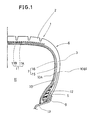
- Fig.1. shows a radial tyre for a passenger car comprising a toroidal hollow main body 6 and an inner liner 7 disposed on the inside surface of the main body.
- the tyre main body 6 has a pair of bead portions 5, a tread portion 2 provided with a tread pattern or grooves on the outer surface thereof, and a pair of sidewall portions 3 extending therebetween.
- the tyre main body 6 is reinforced by a pair of bead cores 9 disposed one in each bead portion 5, a carcass 10 turned up in both edges around the bead cores 9 from the inside to the outside thereof to form a turned up parts 10B and a main part 10A extending between the bead portions 5 through the tread portion 2 and the sidewall portions 3.
- a belt layer 11 is disposed radially outside the crown portion of the carcass 10 the stiffness the tread portion 2.
- the carcass 10 is composed of at least one ply of cords attached at an angle between 50 and 90 degrees with respect to the circumferential direction of the tyre.
- Organic fibre cords such as synthetic resin, inorganic fibre cords such as metal or the like can be used as the carcass cords.
- Each of the carcass turned up parts 10B is extended into its respective sidewall portion 3 and between the carcass main part 10A and each of the turned up parts 10B a bead apex 12 is disposed extending radially outwardly from its bead core 9 to increase the transverse stiffness of the tyre.
- the belt layer 11 is disposed on the crown of the carcass 10, and composed of, for example, two plies 11A and 11B of organic or inorganic stiff cords arranged at a small angle of 0 to 35 degrees to the circumferential direction of the tyre.
- the width of the belt layer is at least 0.75 times the tread width so as to provide a hoop effect over the entire width of the treads thus to stiffen and reinforce the tread 2.
- the inner liner 7 On the inner surface of the tyre main body, in general and in this example, on the inner surface of the carcass main part 10A, the inner liner 7 is disposed.
- the primary object of the inner liner 7 is to provide air-tightness for the tyre which is this a tubeless tyre, that is, to prevent leakage of the air in the doughnut-shaped tyre inner chamber H enclosed by the tyre and its rim 13 when the tyre us mounted there on.
- the special new object of the inner liner 7 is to dampen the resonance of sound in the above mentioned chamber H.
- the inner liner 7 has a double layered structure consisting of an airtight layer 15 and a damper layer 16.
- the damper layer 16 is located on the innermost side so that the inner surface thereof faces the above-mentioned chamber H.
- the airtight layer 15 is located outside the damper later 16 and inside the tyre main body or carcass and covers the entire inner surface thereof.
- the airtight layer 15 is made of 4 soft rubber composition, such as butyl rubber, halogen rubber or the like, which excels in air tightness.
- the damper layer 16 in this embodiment is made of porous material having uniformily distributed tiny independent cavities, like sponge rubber the mean diameter of which is nor more than 10 microns. A great number of the cavities are open at the inner surface of the damper layer 16 to provide pores thereon.
- the base for the porous material is a rubber composition which is of the same kind as the airtight layer 15, but it is also possible to use a different kind of rubber composition. Further, various synthetic resins may be used for the base of the porous material aside from rubber composition.
- the thickness of the damper layer 16 is preferably in a range of 4mm to 10mm, and it should be nearly constant so as not to disturb the tyre dynamic balance.
- the space rate of the porous material which is the ratio of the total volume of the space including the cavities and the pores (that is, the opened cavities) to the apparent whole volume, is preferably not less than 20%. If the rate is less than 20% and/or the diameter is over 10 microns, the effect to damp region resonance in the tyre air chamber is inferior.
- the above mentioned porous material can be made by mixing foaming agent (for example, dinitrosa pentamethylene tetramine, azodicarbonamide, azobisisobutylonitrile, toluenesulfonyl hydrazide and the like) into the rubber base in a raw state, and then heating it in a vulcanising process.
- foaming agent for example, dinitrosa pentamethylene tetramine, azodicarbonamide, azobisisobutylonitrile, toluenesulfonyl hydrazide and the like
- foaming agent for example, dinitrosa pentamethylene tetramine, azodicarbonamide, azobisisobutylonitrile, toluenesulfonyl hydrazide and the like
- the porous material and the airtight rubber material are pressure-bonded into one body, and this layered material is applied to the inner surface of the carcass to form a raw tyre.
- the tyre 1 of the invention in substantially the same process as that for a normal pneumatic tyre, without adding any complex process, thereby preventing the production efficiency from being lowered and the product cost from being increased.
- the above-mentioned independent cavities are tiny foams.
- the damper layer 16 in the present invention can be formed by adhering a preformed porous material to the inside of the airtight layer 15 before or after the tyre vulcanising process.
- porous material having continuous cavities also can be used.
- porous material for example, non woven fabric in which organic or inorganic short fibres are mutually combined by thermocompression bonding or other methods, or woven cloth laminated to the above-mentioned thickness can be used.
- Each test tyre was mounted on 6 1/2 JJX15 rim and inflated to a normal pressure of 2kg/sq.mm and they were installed in a 2000cc passenger car, and then the road noise was measured in the interior of the car while running a rugged asphalt paved road at 50 km/h.
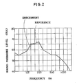
- Fig.2 shows the result of the frequency analysis.
- the noise level of the working example tyre was decreased in the vicinity of 250 Hz over a relatively wide range to decrease the power of the noise and as the result, the road noise was remarkably reduced.
- the pneumatic tyre of the present invention is provided with an inner liner having a porous damper layer 16 the echo by the inside wall of the tyre is attenuated and the noise is absorbed by the porous surface to lower the resonance, and further the transmission of vibration of the tyre main body, which is a main source of the mark, to the air in the tyre inner chamber is also lessened by the porous material.
- the road noise in particular, the peak caused around 250 Hz by the resonance is reduced.
- this structure is extremely simple, and the tyre characteristics are not sacrificed, and it is safe.
- the present invention can be applied to all kinds of pneumatic tyres having an air chamber regardless of carcass structure such as radial or cross ply structure, and size and usage.
Abstract
Description
- The present invention relates to a pneumatic tvre which is provided with an improved inner liner capable of reducing road noise.
- Recently, great pressures have emersed especially for passenger cars to reduce the noise levels. In general, noise from the tyres comprises pattern noise caused by the tread pattern of the tyre, road noise which derives from the roughness of the road surface, and others such as squeal noise, slip noise, vibration noise, etc.
- Road noise is the noise caused in a frequency range of about 50 to 400 Hz when running on a rough road. Surface such noise when transmitted into the vehicle interior can cause resonance and discomfort.
- On the other hand, analysis of the frequency spectrum of the road noise has shown one or more peaks around 250 Hz as shown typically in Fig.3. Therefore, if there was a decrease in peak noise around 250 Hz then there would be a lowering of the road noise perceived in the car.
- The present invention, as a result of various experiments, discovered that the cause of the peak is the resonance of the doughnut-shaped air chamber enclosed by the inner surface of the tyre and the rim. It was confirmed that the road noise can be remarkably lowered by controlling this resonance of the air chamber, that is, vibration of the air in the tyre.
- It is one object of the present invention to provide a pneumatic tyre having reduced road noise in this particular range in the vicinity of 250 Hz, in a simple way and without sacrificing or changing the tyre characteristics especially tyre dynamic performance.
- According to one aspect of the present invention, a pneumatic tyre is provided with an inner liner disposed on the inside thereof, wherein the inner liner has a damper layer provided with a porous surface facing the interior of the tyre.
- Accordingly, the damper layer lowers the Q-factor of the tyre inner chamber in resonance. Thus if the tyre inside wall resounds, the sound or reflected sound or echo is absorbed and attenuated by the inner liner.
- Further, the damper layer may lower the transmission of vibration of the tyre main body to the air in the tyre inner chamber.
- An embodiment of the present invention will now be described, by way of example only, with reference to the drawings, in which:-
- Fig.1. is a sectional view showing an embodiment of the present invention
- Fig.2. is a diagram showing the effect of the present invention and
- Fig.3 is a diagram showing the frequency spectrum of road noise in a prior art tyre.
- Fig.1. shows a radial tyre for a passenger car comprising a toroidal hollow
main body 6 and an inner liner 7 disposed on the inside surface of the main body. - The tyre
main body 6 has a pair ofbead portions 5, atread portion 2 provided with a tread pattern or grooves on the outer surface thereof, and a pair ofsidewall portions 3 extending therebetween. The tyremain body 6 is reinforced by a pair ofbead cores 9 disposed one in eachbead portion 5, acarcass 10 turned up in both edges around thebead cores 9 from the inside to the outside thereof to form a turned up parts 10B and amain part 10A extending between thebead portions 5 through thetread portion 2 and thesidewall portions 3. Abelt layer 11 is disposed radially outside the crown portion of thecarcass 10 the stiffness thetread portion 2. - The
carcass 10 is composed of at least one ply of cords attached at an angle between 50 and 90 degrees with respect to the circumferential direction of the tyre. Organic fibre cords such as synthetic resin, inorganic fibre cords such as metal or the like can be used as the carcass cords. - Each of the carcass turned up parts 10B is extended into its
respective sidewall portion 3 and between the carcassmain part 10A and each of the turned up parts 10B abead apex 12 is disposed extending radially outwardly from itsbead core 9 to increase the transverse stiffness of the tyre. - The
belt layer 11 is disposed on the crown of thecarcass 10, and composed of, for example, twoplies - The width of the belt layer is at least 0.75 times the tread width so as to provide a hoop effect over the entire width of the treads thus to stiffen and reinforce the
tread 2. - On the inner surface of the tyre main body, in general and in this example, on the inner surface of the carcass
main part 10A, the inner liner 7 is disposed. The primary object of the inner liner 7 is to provide air-tightness for the tyre which is this a tubeless tyre, that is, to prevent leakage of the air in the doughnut-shaped tyre inner chamber H enclosed by the tyre and itsrim 13 when the tyre us mounted there on. The special new object of the inner liner 7 is to dampen the resonance of sound in the above mentioned chamber H. To achieve this objective, the inner liner 7 has a double layered structure consisting of anairtight layer 15 and adamper layer 16. - The
damper layer 16 is located on the innermost side so that the inner surface thereof faces the above-mentioned chamber H. - The
airtight layer 15 is located outside the damper later 16 and inside the tyre main body or carcass and covers the entire inner surface thereof. Theairtight layer 15 is made of 4 soft rubber composition, such as butyl rubber, halogen rubber or the like, which excels in air tightness. - The
damper layer 16 in this embodiment is made of porous material having uniformily distributed tiny independent cavities, like sponge rubber the mean diameter of which is nor more than 10 microns. A great number of the cavities are open at the inner surface of thedamper layer 16 to provide pores thereon. The base for the porous material is a rubber composition which is of the same kind as theairtight layer 15, but it is also possible to use a different kind of rubber composition. Further, various synthetic resins may be used for the base of the porous material aside from rubber composition. - The thickness of the
damper layer 16 is preferably in a range of 4mm to 10mm, and it should be nearly constant so as not to disturb the tyre dynamic balance. - The space rate of the porous material which is the ratio of the total volume of the space including the cavities and the pores (that is, the opened cavities) to the apparent whole volume, is preferably not less than 20%. If the rate is less than 20% and/or the diameter is over 10 microns, the effect to damp region resonance in the tyre air chamber is inferior.
- The above mentioned porous material can be made by mixing foaming agent (for example, dinitrosa pentamethylene tetramine, azodicarbonamide, azobisisobutylonitrile, toluenesulfonyl hydrazide and the like) into the rubber base in a raw state, and then heating it in a vulcanising process. In practice, the porous material and the airtight rubber material are pressure-bonded into one body, and this layered material is applied to the inner surface of the carcass to form a raw tyre. Then the raw tyre is vulcanised and the heat of vulcanisation causes the foaming agent to produce the
porous damper layer 16. - Thus it is possible to make the tyre 1 of the invention in substantially the same process as that for a normal pneumatic tyre, without adding any complex process, thereby preventing the production efficiency from being lowered and the product cost from being increased.
- In this embodiment, therefore, the above-mentioned independent cavities are tiny foams.
- The
damper layer 16 in the present invention, however, can be formed by adhering a preformed porous material to the inside of theairtight layer 15 before or after the tyre vulcanising process. - Furthermore, for the damper layer 16 a porous material having continuous cavities also can be used. As such porous material, for example, non woven fabric in which organic or inorganic short fibres are mutually combined by thermocompression bonding or other methods, or woven cloth laminated to the above-mentioned thickness can be used.
- Working example tyres of size 205/60R15 having the structure shown in Fig.1 and reference tyres having the same structure with the exception that no
damper layer 16 provided, were prepared. Thedamper layer 16 was made of a porous rubber material having independent cavities, and the space rate and thickness thereof were 50% and 7mm, respectively. - Each test tyre was mounted on 6 1/2 JJX15 rim and inflated to a normal pressure of 2kg/sq.mm and they were installed in a 2000cc passenger car, and then the road noise was measured in the interior of the car while running a rugged asphalt paved road at 50 km/h. Fig.2 shows the result of the frequency analysis. As apparent therefrom, the noise level of the working example tyre was decreased in the vicinity of 250 Hz over a relatively wide range to decrease the power of the noise and as the result, the road noise was remarkably reduced.
- As described above, since the pneumatic tyre of the present invention is provided with an inner liner having a
porous damper layer 16 the echo by the inside wall of the tyre is attenuated and the noise is absorbed by the porous surface to lower the resonance, and further the transmission of vibration of the tyre main body, which is a main source of the mark, to the air in the tyre inner chamber is also lessened by the porous material. As a result, the road noise, in particular, the peak caused around 250 Hz by the resonance is reduced. Furthermore, this structure is extremely simple, and the tyre characteristics are not sacrificed, and it is safe. - The present invention can be applied to all kinds of pneumatic tyres having an air chamber regardless of carcass structure such as radial or cross ply structure, and size and usage.
Claims (5)
Applications Claiming Priority (2)
| Application Number | Priority Date | Filing Date | Title |
|---|---|---|---|
| JP279559/88 | 1988-11-04 | ||
| JP63279559A JPH02127101A (en) | 1988-11-04 | 1988-11-04 | Pneumatic tire |
Publications (3)
| Publication Number | Publication Date |
|---|---|
| EP0367556A2 true EP0367556A2 (en) | 1990-05-09 |
| EP0367556A3 EP0367556A3 (en) | 1990-11-07 |
| EP0367556B1 EP0367556B1 (en) | 1995-01-25 |
Family
ID=17612661
Family Applications (1)
| Application Number | Title | Priority Date | Filing Date |
|---|---|---|---|
| EP19890311222 Expired - Lifetime EP0367556B1 (en) | 1988-11-04 | 1989-10-31 | Pneumatic tyre |
Country Status (3)
| Country | Link |
|---|---|
| EP (1) | EP0367556B1 (en) |
| JP (1) | JPH02127101A (en) |
| DE (1) | DE68920818T2 (en) |
Cited By (11)
| Publication number | Priority date | Publication date | Assignee | Title |
|---|---|---|---|---|
| EP0614774A1 (en) * | 1993-03-08 | 1994-09-14 | Sumitomo Rubber Industries Limited | Pneumatic radial tyre |
| EP0870631A2 (en) * | 1997-04-10 | 1998-10-14 | Dr.Ing.h.c. F. Porsche Aktiengesellschaft | Motor vehicle wheel |
| EP1676722A1 (en) * | 2004-12-30 | 2006-07-05 | The Goodyear Tire & Rubber Company | Pneumatic tire with sound absorbing innerliner, and method for producing such tire. |
| EP1800911A2 (en) * | 2005-12-20 | 2007-06-27 | The Goodyear Tire & Rubber Company | Tire with integral foamed noise damper |
| DE202008009008U1 (en) | 2008-07-03 | 2008-09-04 | Recticel N.V. | vehicle tires |
| WO2011051203A1 (en) | 2009-10-27 | 2011-05-05 | Societe De Technologie Michelin | Tire, the inner wall of which is provided with a heat-expandable rubber layer |
| WO2016012946A1 (en) * | 2014-07-21 | 2016-01-28 | Bridgestone Corporation | Tyre comprising a foam material for sound absorption |
| WO2016075668A1 (en) * | 2014-11-13 | 2016-05-19 | Bridgestone Corporation | Tyre comprising a foam material for acoustic absorption |
| EP2937229A4 (en) * | 2012-12-19 | 2016-06-22 | Bridgestone Corp | Pneumatic tire, and method of manufacturing pneumatic tire |
| US10632790B2 (en) | 2014-09-12 | 2020-04-28 | Bridgestone Corporation | Pneumatic tire |
| EP3406462B1 (en) | 2017-01-25 | 2020-09-02 | Sumitomo Rubber Industries, Ltd. | Pneumatic tire |
Families Citing this family (9)
| Publication number | Priority date | Publication date | Assignee | Title |
|---|---|---|---|---|
| JPH0640206A (en) * | 1992-07-21 | 1994-02-15 | Bridgestone Corp | Pneumatic tire |
| JPH07276909A (en) * | 1994-04-11 | 1995-10-24 | Sumitomo Rubber Ind Ltd | Pneumatic tire |
| JP2003146005A (en) * | 2001-11-13 | 2003-05-21 | Kimihiro Yokose | Noise reducing tire wheel |
| KR20040036837A (en) * | 2002-10-25 | 2004-05-03 | 금호타이어 주식회사 | Pneumatic tire decreased road noise |
| EP2093080B1 (en) * | 2006-12-06 | 2011-12-21 | Bridgestone Corporation | Pneumatic tire and method of producing the same |
| JP4636126B2 (en) * | 2008-06-17 | 2011-02-23 | 横浜ゴム株式会社 | Pneumatic tire manufacturing method |
| CN106170400B (en) * | 2014-04-09 | 2019-04-02 | 株式会社普利司通 | Pneumatic tire |
| CN111032370B (en) * | 2017-08-22 | 2022-06-17 | 住友橡胶工业株式会社 | Pneumatic tire |
| JP7241481B2 (en) * | 2018-07-03 | 2023-03-17 | Toyo Tire株式会社 | pneumatic tire |
Citations (5)
| Publication number | Priority date | Publication date | Assignee | Title |
|---|---|---|---|---|
| US2290121A (en) * | 1939-06-03 | 1942-07-14 | William A Tripp | Vehicle tire |
| FR1382994A (en) * | 1963-10-03 | 1964-12-24 | Michelin & Cie | Improvement of tire casings that must resist punctures |
| DE2040898A1 (en) * | 1970-08-18 | 1972-02-24 | Heinrich Kunel | Vehicle tires with soundproofing |
| DE3042350A1 (en) * | 1980-11-10 | 1982-05-27 | Teroson Gmbh, 6900 Heidelberg | Reducing noise level from tyres - lining interior with foam of specified youngs modulus density and thickness range |
| EP0029120B1 (en) * | 1979-11-16 | 1984-06-27 | Messerschmitt-Bölkow-Blohm Gesellschaft mit beschränkter Haftung | Arrangement for reducing tyre noises |
Family Cites Families (1)
| Publication number | Priority date | Publication date | Assignee | Title |
|---|---|---|---|---|
| JPH07115563B2 (en) * | 1986-12-19 | 1995-12-13 | 株式会社ブリヂストン | Pneumatic tire with low noise and manufacturing method thereof |
-
1988
- 1988-11-04 JP JP63279559A patent/JPH02127101A/en active Pending
-
1989
- 1989-10-31 DE DE1989620818 patent/DE68920818T2/en not_active Expired - Fee Related
- 1989-10-31 EP EP19890311222 patent/EP0367556B1/en not_active Expired - Lifetime
Patent Citations (5)
| Publication number | Priority date | Publication date | Assignee | Title |
|---|---|---|---|---|
| US2290121A (en) * | 1939-06-03 | 1942-07-14 | William A Tripp | Vehicle tire |
| FR1382994A (en) * | 1963-10-03 | 1964-12-24 | Michelin & Cie | Improvement of tire casings that must resist punctures |
| DE2040898A1 (en) * | 1970-08-18 | 1972-02-24 | Heinrich Kunel | Vehicle tires with soundproofing |
| EP0029120B1 (en) * | 1979-11-16 | 1984-06-27 | Messerschmitt-Bölkow-Blohm Gesellschaft mit beschränkter Haftung | Arrangement for reducing tyre noises |
| DE3042350A1 (en) * | 1980-11-10 | 1982-05-27 | Teroson Gmbh, 6900 Heidelberg | Reducing noise level from tyres - lining interior with foam of specified youngs modulus density and thickness range |
Cited By (17)
| Publication number | Priority date | Publication date | Assignee | Title |
|---|---|---|---|---|
| EP0614774A1 (en) * | 1993-03-08 | 1994-09-14 | Sumitomo Rubber Industries Limited | Pneumatic radial tyre |
| EP0870631A2 (en) * | 1997-04-10 | 1998-10-14 | Dr.Ing.h.c. F. Porsche Aktiengesellschaft | Motor vehicle wheel |
| EP0870631A3 (en) * | 1997-04-10 | 1999-03-31 | Dr.Ing.h.c. F. Porsche Aktiengesellschaft | Motor vehicle wheel |
| EP1676722A1 (en) * | 2004-12-30 | 2006-07-05 | The Goodyear Tire & Rubber Company | Pneumatic tire with sound absorbing innerliner, and method for producing such tire. |
| US7694707B2 (en) | 2005-12-20 | 2010-04-13 | The Goodyear Tire & Rubber Company | Tire with integral foamed noise damper |
| EP1800911A3 (en) * | 2005-12-20 | 2008-04-23 | The Goodyear Tire & Rubber Company | Tire with integral foamed noise damper |
| EP1800911A2 (en) * | 2005-12-20 | 2007-06-27 | The Goodyear Tire & Rubber Company | Tire with integral foamed noise damper |
| DE202008009008U1 (en) | 2008-07-03 | 2008-09-04 | Recticel N.V. | vehicle tires |
| WO2010000789A1 (en) | 2008-07-03 | 2010-01-07 | Recticel N. V. | Vehicle tyre |
| EP2505390A2 (en) | 2008-07-03 | 2012-10-03 | Recticel N.V. | Vehicle tyre |
| WO2011051203A1 (en) | 2009-10-27 | 2011-05-05 | Societe De Technologie Michelin | Tire, the inner wall of which is provided with a heat-expandable rubber layer |
| US8978721B2 (en) | 2009-10-27 | 2015-03-17 | Compagnie Generale Des Etablissements Michelin | Tyre, the inner wall of which is provided with a heat-expandable rubber layer |
| EP2937229A4 (en) * | 2012-12-19 | 2016-06-22 | Bridgestone Corp | Pneumatic tire, and method of manufacturing pneumatic tire |
| WO2016012946A1 (en) * | 2014-07-21 | 2016-01-28 | Bridgestone Corporation | Tyre comprising a foam material for sound absorption |
| US10632790B2 (en) | 2014-09-12 | 2020-04-28 | Bridgestone Corporation | Pneumatic tire |
| WO2016075668A1 (en) * | 2014-11-13 | 2016-05-19 | Bridgestone Corporation | Tyre comprising a foam material for acoustic absorption |
| EP3406462B1 (en) | 2017-01-25 | 2020-09-02 | Sumitomo Rubber Industries, Ltd. | Pneumatic tire |
Also Published As
| Publication number | Publication date |
|---|---|
| DE68920818T2 (en) | 1995-05-24 |
| JPH02127101A (en) | 1990-05-15 |
| DE68920818D1 (en) | 1995-03-09 |
| EP0367556B1 (en) | 1995-01-25 |
| EP0367556A3 (en) | 1990-11-07 |
Similar Documents
| Publication | Publication Date | Title |
|---|---|---|
| EP0367556B1 (en) | Pneumatic tyre | |
| EP1253025B1 (en) | Tire noise reducing system | |
| US7347239B2 (en) | Tire noise reducing system | |
| CN108513551B (en) | Pneumatic tire | |
| US11648807B2 (en) | Post-cure run-flat and/or noise reduction apparatus and method of manufacturing the same | |
| EP1184207B1 (en) | Tyre noise reducing system | |
| JP2008285156A (en) | Tire with reduced rolling noise | |
| JP2003285607A (en) | Pneumatic tire | |
| EP0686514B1 (en) | Pneumatic radial tyre and method of making the same | |
| EP1125771B1 (en) | Tyre noise reducing system | |
| EP3722113B1 (en) | Pneumatic tire comprising resonance noise reduction structure | |
| JP5274106B2 (en) | Tire with bubble layer | |
| JP2975438B2 (en) | Pneumatic tire | |
| EP0893236A1 (en) | Self-sealing tyre and method of making the same | |
| EP0614774B1 (en) | Pneumatic radial tyre | |
| US20020144760A1 (en) | Method and deadening device for reducing the noise in a vehicle during travel, and tyre wheel provided with the said device | |
| EP1214205B1 (en) | Method and deadening device for reducing the noise in a vehicle during travel, and tyre wheel provided with said device | |
| JPH07115563B2 (en) | Pneumatic tire with low noise and manufacturing method thereof | |
| JP2002205515A (en) | Pneumatic tire | |
| JPH07276909A (en) | Pneumatic tire | |
| JPH11170813A (en) | Pneumatic tire for heavy load | |
| JP2020121688A (en) | Pneumatic tire | |
| CN111372792A (en) | Pneumatic tire | |
| JPH06344722A (en) | Low-noise tire | |
| JP2001088501A (en) | Assembly of tire and disc wheel |
Legal Events
| Date | Code | Title | Description |
|---|---|---|---|
| PUAI | Public reference made under article 153(3) epc to a published international application that has entered the european phase |
Free format text: ORIGINAL CODE: 0009012 |
|
| AK | Designated contracting states |
Kind code of ref document: A2 Designated state(s): DE FR GB |
|
| PUAL | Search report despatched |
Free format text: ORIGINAL CODE: 0009013 |
|
| AK | Designated contracting states |
Kind code of ref document: A3 Designated state(s): DE FR GB |
|
| 17P | Request for examination filed |
Effective date: 19901210 |
|
| 17Q | First examination report despatched |
Effective date: 19920522 |
|
| GRAA | (expected) grant |
Free format text: ORIGINAL CODE: 0009210 |
|
| AK | Designated contracting states |
Kind code of ref document: B1 Designated state(s): DE FR GB |
|
| REF | Corresponds to: |
Ref document number: 68920818 Country of ref document: DE Date of ref document: 19950309 |
|
| ET | Fr: translation filed | ||
| PLBE | No opposition filed within time limit |
Free format text: ORIGINAL CODE: 0009261 |
|
| STAA | Information on the status of an ep patent application or granted ep patent |
Free format text: STATUS: NO OPPOSITION FILED WITHIN TIME LIMIT |
|
| 26N | No opposition filed | ||
| PGFP | Annual fee paid to national office [announced via postgrant information from national office to epo] |
Ref country code: FR Payment date: 19981009 Year of fee payment: 10 |
|
| PGFP | Annual fee paid to national office [announced via postgrant information from national office to epo] |
Ref country code: GB Payment date: 19981106 Year of fee payment: 10 Ref country code: DE Payment date: 19981106 Year of fee payment: 10 |
|
| PG25 | Lapsed in a contracting state [announced via postgrant information from national office to epo] |
Ref country code: GB Free format text: LAPSE BECAUSE OF NON-PAYMENT OF DUE FEES Effective date: 19991031 |
|
| GBPC | Gb: european patent ceased through non-payment of renewal fee |
Effective date: 19991031 |
|
| PG25 | Lapsed in a contracting state [announced via postgrant information from national office to epo] |
Ref country code: FR Free format text: LAPSE BECAUSE OF NON-PAYMENT OF DUE FEES Effective date: 20000630 |
|
| PG25 | Lapsed in a contracting state [announced via postgrant information from national office to epo] |
Ref country code: DE Free format text: LAPSE BECAUSE OF NON-PAYMENT OF DUE FEES Effective date: 20000801 |
|
| REG | Reference to a national code |
Ref country code: FR Ref legal event code: ST |