EP0367481B1 - Infrarot-Frontsicht-Abbildungssystem - Google Patents
Infrarot-Frontsicht-Abbildungssystem Download PDFInfo
- Publication number
- EP0367481B1 EP0367481B1 EP89310963A EP89310963A EP0367481B1 EP 0367481 B1 EP0367481 B1 EP 0367481B1 EP 89310963 A EP89310963 A EP 89310963A EP 89310963 A EP89310963 A EP 89310963A EP 0367481 B1 EP0367481 B1 EP 0367481B1
- Authority
- EP
- European Patent Office
- Prior art keywords
- radiation
- reimaging
- scene
- thermal
- detector
- Prior art date
- Legal status (The legal status is an assumption and is not a legal conclusion. Google has not performed a legal analysis and makes no representation as to the accuracy of the status listed.)
- Expired - Lifetime
Links
- 238000003331 infrared imaging Methods 0.000 title claims description 5
- 230000005855 radiation Effects 0.000 claims description 39
- 230000003287 optical effect Effects 0.000 claims description 23
- 238000000034 method Methods 0.000 claims description 22
- 238000003384 imaging method Methods 0.000 claims description 9
- 238000012545 processing Methods 0.000 claims description 6
- 230000008569 process Effects 0.000 claims description 2
- 230000006872 improvement Effects 0.000 description 6
- 238000003491 array Methods 0.000 description 5
- 238000012986 modification Methods 0.000 description 5
- 230000004048 modification Effects 0.000 description 5
- 238000013461 design Methods 0.000 description 2
- 238000004519 manufacturing process Methods 0.000 description 2
- 230000001360 synchronised effect Effects 0.000 description 2
- 238000013459 approach Methods 0.000 description 1
- 230000000712 assembly Effects 0.000 description 1
- 238000000429 assembly Methods 0.000 description 1
- 230000008901 benefit Effects 0.000 description 1
- 238000001816 cooling Methods 0.000 description 1
- 230000000694 effects Effects 0.000 description 1
- 238000009472 formulation Methods 0.000 description 1
- 238000010348 incorporation Methods 0.000 description 1
- 239000000463 material Substances 0.000 description 1
- 239000000203 mixture Substances 0.000 description 1
- 238000010606 normalization Methods 0.000 description 1
- 210000001747 pupil Anatomy 0.000 description 1
- 230000000717 retained effect Effects 0.000 description 1
- 239000004065 semiconductor Substances 0.000 description 1
- 238000000926 separation method Methods 0.000 description 1
- 230000006641 stabilisation Effects 0.000 description 1
- 238000011105 stabilization Methods 0.000 description 1
- 238000006467 substitution reaction Methods 0.000 description 1
Images

Classifications
-
- H—ELECTRICITY
- H04—ELECTRIC COMMUNICATION TECHNIQUE
- H04N—PICTORIAL COMMUNICATION, e.g. TELEVISION
- H04N3/00—Scanning details of television systems; Combination thereof with generation of supply voltages
- H04N3/02—Scanning details of television systems; Combination thereof with generation of supply voltages by optical-mechanical means only
- H04N3/08—Scanning details of television systems; Combination thereof with generation of supply voltages by optical-mechanical means only having a moving reflector
- H04N3/09—Scanning details of television systems; Combination thereof with generation of supply voltages by optical-mechanical means only having a moving reflector for electromagnetic radiation in the invisible region, e.g. infrared
Definitions
- This invention relates to forward looking infrared imaging systems and, more particularly, to components and methods for forming and modifying such systems.
- FLIR imaging systems incorporate photodetector arrays of photosensitive semiconductor materials such as Hg 1-X Cd X Te which can be formulated to respond to wavelengths in the 3 - 5 and 8 - 12 micrometer atmospheric windows. Both p-n junction photodiode arrays and MIS photocapacitor arrays of Hg 1-X Cd X Te provide satisfactory focal plane imaging in the infrared regime. These systems produce standard video pictures wherein the thermal temperatures of the viewed scene are displayed as various shades of gray.
- An additional mirror may be required to complete the optical path, particularly if an existing system is being upgraded to include the thermal reference source.
- Introduction of the mirrors, as well as an electromechanical system to effect synchronous rotation, can be a difficult and costly task, especially in existing systems, because of severe space constraints and the requirements for moving parts and circuitry for effecting synconous chopping.
- a reimaging afocal may be introduced in lieu of a Galilean afocal to provide an image plane for the introduction of thermal sources in front of the scanner.
- the thermal sources can be scanned along with the field of view.
- different FLIR systems often require different fields of view or different afocal levels of magnification.
- introduction of the thermal reference source would require redesign for each distinct application.
- reimaging afocals are considerably more expensive and require more space than Galilean afocals.
- the present invention provides a method of modifying an existing forward looking infrared imaging system wherein the system is of the type which processes radiation received from a scene to form an image of the scene, wherein the system includes a Galilean afocal lens combination, sensor components including a detector element array of the type which subtends the field of view along a first direction, an imaging lens system arranged to focus collimated radiation upon the detector, and a scanning device for varying the field of view along a second direction in order to provide a two dimensional image, the method comprising the steps of: forming a reimaging afocal lens system comprising at least first and second lenses and a plane on which is formed an image of the scene therebetween; positioning a thermal reference source in the reimaging system; and positioning the reimaging system along the optical path of the existing system between the Galilean lens combination and the scanning device.
- the present invention also provides a forward looking infrared system for processing radiation received from a scene to form an image thereof comprising: an infrared detector element array of the type which subtends the field of view along a first direction; an imaging lens system for focusing collimated radiation upon the detector; a scanning mirror for varying the field of view along a second direction in order to provide a two dimensional image of the scene; a Galilean afocal lens system positioned to receive radiation from the scene; and a reimaging afocal lens system positioned between the Galilean afocal lens system and the scanning mirror, said reimaging system including at least first and second lenses for forming an image of the scene at a reimaging plane therebetween and for providing collimated radiation to the scanning mirror; and a thermal reference source positioned in the reimaging system.
- the present invention further provides a method of processing radiation received from a scene in which reference thermal radiation is taken into account, comprising: receiving radiation from the scene using a Galilean afocal lens combination and directing the radiation along an optical path, producing an intermediate image of the scene on a plane on the optical path, supplying the reference thermal radiation at or near the plane of the intermediate image, focusing the radiation from the scene upon and directing the reference thermal radiation on to a detector which extends along a first direction so as to subtend a field of view, and so scanning the field of view along a second direction that the detector is responsive to a two dimensional area.
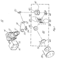
- Figure 1 illustrates in partial schematic form an exemplary parallel scan forward looking infrared imaging system 10 constructed according to the invention.
- the system includes a Hg 1-X Cd X Te linear array infrared detector 12 contained in a dewar 13 and coupled to a cryogenic cooler 14.
- the detector comprises a vertical array of elements which are photosensitive to radiation in either or both the 3 - 5 and 8 - 12 micrometer range.
- the detector 12 may comprise a column of 240 or 480 elements, or may include multiple parallel columns of elements.
- the detector 12 is coupled to processing electronics 15 which, in the preferred embodiments, includes circuitry 16 for performing DC restoration and/or detector electronic gain balance functions.
- the detector array subtends the field of view in a first, e.g., vertical, direction.
- Incoming radiation is scanned with mirror optics along a second direction and reflected upon the array to provide information for generating a two dimensional image.
- Limitations in system resolution due to separation distances between detector elements may require interlacing between successive fields to complete a frame.
- the cooler may be of the split cycle variety with the expander portion of the cooler in the dewar.
- the compressor portion of the cooler (not illustrated) is located in a convenient position near the dewar and is connected to the expander portion by a tube. Electronics utilized with the complete system is not integral to the invention and is therefore not described with detail.
- the detector 12 receives radiation from a scene along an optical path which includes an imager 18, a mirror scanner 20, a reimaging afocal lens system 22 and a Galilean afocal lens system 26.
- the detector 12 in combination with the imager 18 and the scanner 20 form the optical sensor portion of the system 10.
- the imager 18, positioned to focus collimated radiation upon the detector 12, comprises at least a pair of lenses 30 and 32 and may include a fold mirror 34 positioned in between the lenses to provide a turn in the optical path.
- the scanner 20 is mechanically driven to subtend the field of view in a direction perpendicular to the direction subtended by the detector array.
- a position sensor (not illustrated) is coupled to the scanner 20 to provide electrical pulses at various positions of the mirror scanner for displaying the sensor output.
- the reimaging afocal lens system 22 is positioned in front of the scanner 20 to receive collimated radiation from the Galilean afocal system 26.
- the reimaging system 22 requires two lenses.
- it comprises three lenses 40, 42 and 44, forming a color correcting combination, and two fold mirrors 46 and 48 positioned between lenses 40 and 44.
- An intermediate image plane 50 is formed between the lenses 40 and 44.
- the region 54 of the image plane 50 corresponds to that portion in which an image of the scene is formed when the system is adjusted to provide a maximum field of view.
- the reimaging system includes range and thermal focal adjustments which are indicated schematically by an arrow 52 positioned along side lens 44.
- Mirror 46 may be used to perform interlace.
- one or more thermal reference sources e.g., a pair of sources 58, such as, for example, thermo-electric coolers, may be fixed in the image plane 50.
- the reference sources 58 are positioned outside the region 54. Only one reference source is required to perform the DC restoration function. A pair of sources is required for gain normalization.
- each thermal source 58 is positioned out of focus so as to remove nonuniformities and provide the same temperature reading to each detector element. This can be effected by positioning a pair of mirrors 55 in the image plane 50 as illustrated in Figure 2. Pairs, each comprising a focusing lens 59 and a reference source 58, are cooperatively positioned to condense radiation from a reference source onto each mirror 55. Each reference source is located at a pupil or aperture plane so as not to be focused on the mirror 55. This arrangement removes nonuniformities which would otherwise be viewed by individual detector elements.
- Prior art FLIR systems are not known to include a reimaging afocal lens system 22 in combination with a Galilean afocal system.
- a function of the reimaging system 22 is to facilitate the use of existing Galilean afocals in FLIR systems which are upgraded to include DC restoration or detector electronic gain balance circuitry which circuitry requires inclusion of a thermal reference source. Otherwise modifications in system resolution and field of view would have to be performed by the reimaging afocal at much greater expense.
- the reimaging system 22 is of a standard size and optical design such that it may be incorporated in a wide variety of existing, e.g., common module, and new systems which also comprise a Galilean afocal system --not-withstanding differing geometric and physical constraints as well as differences in optical performance parameters among the variety of systems.
- Formulation of a standard reimaging system allows for more economical upgrading and fabrication of FLIR systems.
- a benefit of using a standard size reimaging afocal is that existing systems can be updated without discarding Galilean afocals and their gimbal pointing and stabilization turrets.
- One of the most expensive components of the FLIR system, the afocal lens switching assembly could thus be retained.
- the invention includes a method for replacing a component of the optical sensor, e.g., the detector 12, or an electronic component in an existing first FLIR system with a component which requires a thermal reference source.
- the electronic component may, for example, include circuitry for performing DC restoration and/or detector electronic gain balance functions.
- the senor portion may be of the type which does not require cooling and the lens systems illustrated may be modified to include reflective lenses instead of refractive lenses. Accordingly, the scope of the invention is only to be limited by the claims which follow.
Landscapes
- Physics & Mathematics (AREA)
- Health & Medical Sciences (AREA)
- Electromagnetism (AREA)
- Toxicology (AREA)
- Engineering & Computer Science (AREA)
- Multimedia (AREA)
- Signal Processing (AREA)
- Transforming Light Signals Into Electric Signals (AREA)
- Radiation Pyrometers (AREA)
- Lenses (AREA)
- Photometry And Measurement Of Optical Pulse Characteristics (AREA)
Claims (16)
- Verfahren zum Modifizieren eines existierenden, nach vorne gerichteten Infrarot-Abbildungssystems (10), wobei das System ein System des Typs ist, bei dem von einer Szene empfangene Strahlung zur Erzeugung eines Abbildes der Szene verarbeitet wird, wobei das System eine galiläische, afokale Linsenkombination (26) Sensorbaueinheiten einschließlich eines Detektorelementfeldes (12) des Typs, bei dem das Gesichtsfeld längs einer ersten Richtung aufspannt, ein Abbildungslinsensystem (18), das so angeordnet ist, daß sie kollimierte Strahlung auf den Detektor (12) fokussiert, und eine Abtastvorrichtung (20) zum Verändern des Gesichtsfeldes längs einer zweiten Richtung zur Erzielung eines zweidimensionalen Bildes enthält, wobei das Verfahren die Schritte enthält:
Bilden eines wiederabbildenden afokalen Linsensystems (22) zum mit wenigstens einer ersten und einer zweiten Linse und einer Ebene (50), auf der dazwischen ein Abbild der Szene erzeugt wird;
Positionieren einer thermischen Referenzquelle (58) in dem wiederabbildenden System; und
Positionieren des wiederabbildenden Systems (22) längs des optischen Weges des existierenden Systems (10) zwischen der galiläischen Linsenkombination (26) und der Abtastvorrichtung (20). - Verfahren nach Anspruch 1, ferner enthaltend den Schritt des Ersetzens des Detektorfeldes (12) des existierenden Systems (10) durch ein anderes Detektorfeld.
- Verfahren nach Anspruch 1 oder 2, ferner enthaltend den Schritt des Einfügens einer Schaltung zur Durchführung von Verstärkungsabgleichfunktionen der Detektorelektronik in das existierende System (10).
- Verfahren nach Anspruch 1, 2 oder 3, ferner enthaltend den Schritt des Einfügens einer Schaltung zur Durchführung einer Gleichstrom-Wiederherstellung in das existierende System (10).
- Verfahren nach Anspruch 1, bei welchem eine erste und eine zweite thermische Referenzquelle (58) in dem wiederabbildenden afokalen Linsensystem (22) so positioniert werden, daß gleichmäßigere Temperaturablesungen für jedes Detektorelement des Feldes (12) erzielt werden, wobei das Verfahren ferner die Schritte enthält:
Positionieren eines ersten und eines zweiten Spiegels (55) in der Abbildungsebene (50) des wiederabbildenden afokalen Systems (22);
kooperatives Positionieren einer ersten Fokussierungslinse (59) und der ersten Referenzquelle (58) zum Konzentrieren von Strahlung aus der Referenzquelle (58) auf den ersten Spiegel (55); und
kooperatives Positionieren einer zweiten Fokussierungslinse (59) und der zweiten Referenzquelle (58) zum Konzentrieren von Strahlung aus der Referenzquelle (58) auf den zweiten Spiegel (55). - Verfahren nach Anspruch 1, ferner enthaltend den Schritt des Ersetzens einer optischen oder elektronischen Komponente im System (10) durch eine Komponente, die die Verwendung der thermischen Referenzquelle (58) ermöglicht.
- Vorwärtsblickendes Infrarotsystem zum Verarbeiten einer Strahlung, die von einer Szene empfangen wird, um deren Abbild zu erzeugen, enthaltend:
ein Infrarot-Detektorelementfeld (12) des Typs, der das Gesichtsfeld längs einer ersten Richtung aufspannt;
ein Abbildungslinsensystem (18) zum Fokussieren einer kollimierten Strahlung auf den Detektor;
einen Abtastspiegel (20) zum Verändern des Gesichtsfeldes längs einer zweiten Richtung, zur Erzielung einer zweidimensionalen Abbildung der Szene;
ein galiläisches afokales Linsensystem (26), das so positioniert ist, daß es Strahlung von der Szene empfängt; und
ein wiederabbildendes afokales Linsensystem (22), das zwischen dem galiläischen afokalen Linsensystem und dem Abtastspiegel angeordnet ist, wobei das wiederabbildende System wenigstens eine erste und eine zweite Linse zur Erzeugung eines Abbildes der Szene an einer dazwischenliegenden Wiederabbildungsebene (50) und zur Erzielung einer kollimierten Strahlung auf den Abtastspiegel (20) enthält; und
eine thermische Referenzquelle (58), die in dem wiederabbildenden System (22) angebracht ist. - Vorwärtsblickendes Infrarotsystem nach Anspruch 7, bei welchem die thermische Referenzquelle (58) in der Wiederabbildungsebene (50) des wiederabbildenden afokalen Linsensystems (22) angeordnet ist.
- Vorwärtsblickendes Infrarotsystem nach Anspruch 7, bei welchem die relativen Positionen der Linsen des wiederabbildenden afokalen Linsensystems (22) einstellbar sind.
- Vorwärtsblickendes Infrarotsystem nach Anspruch 7, bei welchem eine erste und eine zweite thermische Referenzquelle (58) so in dem wiederabbildenden afokalen Linsensystem (22) angeordnet sind, daß gleichmäßigere Temperaturablesungen für jedes Detektorelement erzielt werden, wobei das System ferner enthält:
einen ersten und einen zweiten Spiegel (55) in der Abbildungsebene (50) des wiederabbildenden afokalen Systems (22);
eine erste Fokussierungslinse (59), die so positioniert ist, daß sie Strahlung von der ersten Referenzquelle (58) auf den ersten Spiegel (55) konzentriert; und
eine zweite Fokussierungslinse (59), die so positioniert ist, daß sie Strahlung von der zweiten Referenzquelle (58) auf den zweiten Spiegel konzentriert. - Vorwärtsblickendes Infrarotsystem nach Anspruch 7, bei welchem das galiläische afokale Linsensystem (26) einstellbar ist, damit die Brennweite und das Gesichtsfeld des vorwärtsblickenden Infrarotsystems modifiziert werden.
- Vorwärtsblickendes Infrarotsystem nach Anspruch 7, bei welchem das wiederabbildende afokale Linsensystem (22) wenigstens eine dritte Linse mit der ersten und der zweiten Linse enthält.
- Vorwärtsblickendes Infrarotsystem nach Anspruch 7, bei welchem das wiederabbildende afokale Linsensystem (22) wenigstens einen Umlenkspiegel (46, 48) mit der ersten und der zweiten Linse enthält, damit der optische Weg auf die Ablenkvorrichtung (20) gelenkt wird.
- Verfahren zum Verarbeiten einer von einer Szene empfangenen Strahlung, bei welchem eine thermische Referenzstrahlung berücksichtigt wird, enthaltend:
Empfangen von Strahlung von der Szene unter Verwendung einer galiläischen afokalen Linsenkombination (26) und Lenken der Strahlung längs eines optischen Weges,
Erzeugen eines Zwischenabbildes der Szene auf einer Ebene (50) auf dem optischen Weg,
Liefern einer thermischen Referenzstrahlung bei oder nahe der Ebene (50) des Zwischenabbildes,
Fokussieren der Strahlung von der Szene und Lenken der thermischen Referenzstrahlung auf einen Detektor (12), der sich längs einer ersten Richtung so erstreckt, daß ein Gesichtsfeld aufgespannt wird, und
Abtasten des Gesichtsfeldes längs einer zweiten Richtung, so daß der Detektor (12) auf ein zweidimensionales Gebiet anspricht. - Verfahren nach Anspruch 14, bei welchem die thermische Referenzstrahlung von einer oder von mehreren Referenzquellen (58) bei oder nahe der Ebene (50) des Zwischenabbildes geliefert wird.
- Verfahren nach Anspruch 14, bei welchem die thermische Referenzstrahlung durch Fokussieren einer oder mehrerer thermischer Referenzquellen (58) auf einen oder mehrere Spiegel (55) bei oder nahe der Ebene (50) des Zwischenabbildes geliefert wird.
Applications Claiming Priority (2)
| Application Number | Priority Date | Filing Date | Title |
|---|---|---|---|
| US07/265,365 US4983837A (en) | 1988-10-31 | 1988-10-31 | Forward looking infrared imaging system |
| US265365 | 1988-10-31 |
Publications (3)
| Publication Number | Publication Date |
|---|---|
| EP0367481A2 EP0367481A2 (de) | 1990-05-09 |
| EP0367481A3 EP0367481A3 (en) | 1990-12-19 |
| EP0367481B1 true EP0367481B1 (de) | 1995-12-27 |
Family
ID=23010132
Family Applications (1)
| Application Number | Title | Priority Date | Filing Date |
|---|---|---|---|
| EP89310963A Expired - Lifetime EP0367481B1 (de) | 1988-10-31 | 1989-10-24 | Infrarot-Frontsicht-Abbildungssystem |
Country Status (4)
| Country | Link |
|---|---|
| US (1) | US4983837A (de) |
| EP (1) | EP0367481B1 (de) |
| KR (1) | KR0137387B1 (de) |
| DE (1) | DE68925267T2 (de) |
Families Citing this family (11)
| Publication number | Priority date | Publication date | Assignee | Title |
|---|---|---|---|---|
| US5276321A (en) * | 1991-04-15 | 1994-01-04 | Geophysical & Environmental Research Corp. | Airborne multiband imaging spectrometer |
| DE4235772A1 (de) * | 1992-10-23 | 1994-04-28 | Menke Josef F | IR-Fernthermometer |
| US5343040A (en) * | 1993-06-10 | 1994-08-30 | Martin Marietta Corporation | Thermal reference technique for flir sensors |
| US5479016A (en) * | 1994-08-25 | 1995-12-26 | The United States Of America As Represented By The Secretary Of The Army | Compact Second Generation FLIR kit |
| DE19601961C2 (de) * | 1996-01-20 | 1998-11-05 | Dornier Gmbh | Einrichtung zur Erleichterung des Auffindens von Zielen an einem Waffensystem |
| IT1286578B1 (it) * | 1996-03-25 | 1998-07-15 | Galileo Spa Off | Sensore di immagini infrarosse con servizi incorporati |
| US6274868B1 (en) * | 1997-07-23 | 2001-08-14 | The United States Of America As Represented By The Secretary Of The Army | All purpose FLIR kit for aircraft |
| EP1257118A1 (de) * | 2001-05-11 | 2002-11-13 | FINMECCANICA S.p.A. | Vorrichtung zur Ausführung einer Temperaturreferenz in einer Infrarot-Kamera und Kamera mit dieser Vorrichtung |
| US7086318B1 (en) * | 2002-03-13 | 2006-08-08 | Bae Systems Land & Armaments L.P. | Anti-tank guided missile weapon |
| KR100377329B1 (en) * | 2002-06-27 | 2003-03-26 | Agency Defense Dev | Automatic scan device and method with scan width and rate dependent on view field of zoom optical system |
| USD871412S1 (en) * | 2016-11-21 | 2019-12-31 | Datalogic Ip Tech S.R.L. | Optical scanner |
Family Cites Families (4)
| Publication number | Priority date | Publication date | Assignee | Title |
|---|---|---|---|---|
| US4280050A (en) * | 1980-03-17 | 1981-07-21 | The United States Of America As Represented By The Secretary Of The Army | Infrared viewer and spectral radiometer |
| GB2100548B (en) * | 1981-06-09 | 1985-01-03 | British Aerospace | Thermal images |
| US4419692A (en) * | 1981-12-31 | 1983-12-06 | Texas Medical Instruments, Inc. | High speed infrared imaging system |
| US4427259A (en) * | 1982-08-23 | 1984-01-24 | Rockwell International Corporation | Selectable field-of-view infrared lens |
-
1988
- 1988-10-31 US US07/265,365 patent/US4983837A/en not_active Expired - Fee Related
-
1989
- 1989-10-24 EP EP89310963A patent/EP0367481B1/de not_active Expired - Lifetime
- 1989-10-24 DE DE68925267T patent/DE68925267T2/de not_active Expired - Fee Related
- 1989-10-30 KR KR1019890015621A patent/KR0137387B1/ko not_active Expired - Fee Related
Also Published As
| Publication number | Publication date |
|---|---|
| KR0137387B1 (ko) | 1998-04-27 |
| DE68925267D1 (de) | 1996-02-08 |
| US4983837A (en) | 1991-01-08 |
| DE68925267T2 (de) | 1996-05-15 |
| EP0367481A3 (en) | 1990-12-19 |
| EP0367481A2 (de) | 1990-05-09 |
| KR900007223A (ko) | 1990-05-09 |
Similar Documents
| Publication | Publication Date | Title |
|---|---|---|
| US4419692A (en) | High speed infrared imaging system | |
| US4806761A (en) | Thermal imager incorporating electronics module having focal plane sensor mosaic | |
| EP0367481B1 (de) | Infrarot-Frontsicht-Abbildungssystem | |
| EP0474480B1 (de) | Anzeigeanordnung | |
| EP0277696B1 (de) | Thermische Abbildungsvorrichtung | |
| US5663825A (en) | Stabilized step/stare scanning device | |
| US3941923A (en) | Thermal imaging system with redundant object space scanning | |
| EP2735143A2 (de) | Rolling-shutter-bildgebungssystem mit synchronisierter abtastbeleuchtung und verfahren für höherauflösende bildgebung | |
| US5717208A (en) | Staring IR-FPA with dither-locked frame circuit | |
| AU579222B2 (en) | Multiple field of view sensor | |
| US6591021B1 (en) | Method and apparatus for correcting the gray levels of images of a digital infrared camera | |
| US5091646A (en) | Integrated thermal imaging system | |
| US5025313A (en) | System for minimizing optical distortions and chromatic aberrations in a linear color scanner | |
| US4714960A (en) | Television rate optical scanner | |
| US5452085A (en) | Spectrographic astigmatism correction system | |
| EP0123038B1 (de) | Optische Abtastvorrichtung | |
| WO1986006214A1 (en) | Thermal imager incorporating sensor within electronics module | |
| EP0766113A2 (de) | Asphärische Elemente für Infrarot-Abbildungssystem | |
| US20040099787A1 (en) | System and method for determining optical aberrations in scanning imaging systems by phase diversity | |
| US5866900A (en) | Method and apparatus for calibrating a focal plane array of an image detector | |
| GB2268353A (en) | Imaging apparatus | |
| US4109149A (en) | Shade reducing aperture stop for thermal imaging systems | |
| EP0188240A2 (de) | Vorrichtung zur Bestimmung der besten Fokussierposition | |
| GB2248310A (en) | Thermal imaging apparatus | |
| Aspin et al. | High spatial resolution ‘shift-and-add’imaging at UKIRT: multiplicity amongst young stellar objects |
Legal Events
| Date | Code | Title | Description |
|---|---|---|---|
| PUAI | Public reference made under article 153(3) epc to a published international application that has entered the european phase |
Free format text: ORIGINAL CODE: 0009012 |
|
| AK | Designated contracting states |
Kind code of ref document: A2 Designated state(s): DE FR GB IT NL |
|
| PUAL | Search report despatched |
Free format text: ORIGINAL CODE: 0009013 |
|
| AK | Designated contracting states |
Kind code of ref document: A3 Designated state(s): DE FR GB IT NL |
|
| 17P | Request for examination filed |
Effective date: 19910523 |
|
| 17Q | First examination report despatched |
Effective date: 19930816 |
|
| GRAA | (expected) grant |
Free format text: ORIGINAL CODE: 0009210 |
|
| AK | Designated contracting states |
Kind code of ref document: B1 Designated state(s): DE FR GB IT NL |
|
| REF | Corresponds to: |
Ref document number: 68925267 Country of ref document: DE Date of ref document: 19960208 |
|
| ITF | It: translation for a ep patent filed | ||
| ET | Fr: translation filed | ||
| PLBE | No opposition filed within time limit |
Free format text: ORIGINAL CODE: 0009261 |
|
| STAA | Information on the status of an ep patent application or granted ep patent |
Free format text: STATUS: NO OPPOSITION FILED WITHIN TIME LIMIT |
|
| 26N | No opposition filed | ||
| NLS | Nl: assignments of ep-patents |
Owner name: RAYTHEON TI SYSTEMS, INC. |
|
| PGFP | Annual fee paid to national office [announced via postgrant information from national office to epo] |
Ref country code: NL Payment date: 19980914 Year of fee payment: 10 |
|
| PGFP | Annual fee paid to national office [announced via postgrant information from national office to epo] |
Ref country code: GB Payment date: 19981001 Year of fee payment: 10 |
|
| PGFP | Annual fee paid to national office [announced via postgrant information from national office to epo] |
Ref country code: FR Payment date: 19981006 Year of fee payment: 10 |
|
| PGFP | Annual fee paid to national office [announced via postgrant information from national office to epo] |
Ref country code: DE Payment date: 19981028 Year of fee payment: 10 |
|
| REG | Reference to a national code |
Ref country code: GB Ref legal event code: 732E |
|
| REG | Reference to a national code |
Ref country code: FR Ref legal event code: TP |
|
| NLS | Nl: assignments of ep-patents |
Owner name: RAYTHEON COMPANY |
|
| REG | Reference to a national code |
Ref country code: GB Ref legal event code: 732E |
|
| REG | Reference to a national code |
Ref country code: FR Ref legal event code: TP |
|
| PG25 | Lapsed in a contracting state [announced via postgrant information from national office to epo] |
Ref country code: GB Free format text: LAPSE BECAUSE OF NON-PAYMENT OF DUE FEES Effective date: 19991024 |
|
| PG25 | Lapsed in a contracting state [announced via postgrant information from national office to epo] |
Ref country code: NL Free format text: LAPSE BECAUSE OF NON-PAYMENT OF DUE FEES Effective date: 20000501 |
|
| GBPC | Gb: european patent ceased through non-payment of renewal fee |
Effective date: 19991024 |
|
| PG25 | Lapsed in a contracting state [announced via postgrant information from national office to epo] |
Ref country code: FR Free format text: LAPSE BECAUSE OF NON-PAYMENT OF DUE FEES Effective date: 20000630 |
|
| NLV4 | Nl: lapsed or anulled due to non-payment of the annual fee |
Effective date: 20000501 |
|
| PG25 | Lapsed in a contracting state [announced via postgrant information from national office to epo] |
Ref country code: DE Free format text: LAPSE BECAUSE OF NON-PAYMENT OF DUE FEES Effective date: 20000801 |
|
| REG | Reference to a national code |
Ref country code: FR Ref legal event code: ST |
|
| PG25 | Lapsed in a contracting state [announced via postgrant information from national office to epo] |
Ref country code: IT Free format text: LAPSE BECAUSE OF NON-PAYMENT OF DUE FEES;WARNING: LAPSES OF ITALIAN PATENTS WITH EFFECTIVE DATE BEFORE 2007 MAY HAVE OCCURRED AT ANY TIME BEFORE 2007. THE CORRECT EFFECTIVE DATE MAY BE DIFFERENT FROM THE ONE RECORDED. Effective date: 20051024 |