EP0367415B1 - Air bag restraint systems - Google Patents
Air bag restraint systems Download PDFInfo
- Publication number
- EP0367415B1 EP0367415B1 EP89310221A EP89310221A EP0367415B1 EP 0367415 B1 EP0367415 B1 EP 0367415B1 EP 89310221 A EP89310221 A EP 89310221A EP 89310221 A EP89310221 A EP 89310221A EP 0367415 B1 EP0367415 B1 EP 0367415B1
- Authority
- EP
- European Patent Office
- Prior art keywords
- air bag
- inflator
- arming
- screw
- slide
- Prior art date
- Legal status (The legal status is an assumption and is not a legal conclusion. Google has not performed a legal analysis and makes no representation as to the accuracy of the status listed.)
- Expired - Lifetime
Links
Images

Classifications
-
- B—PERFORMING OPERATIONS; TRANSPORTING
- B60—VEHICLES IN GENERAL
- B60R—VEHICLES, VEHICLE FITTINGS, OR VEHICLE PARTS, NOT OTHERWISE PROVIDED FOR
- B60R21/00—Arrangements or fittings on vehicles for protecting or preventing injuries to occupants or pedestrians in case of accidents or other traffic risks
- B60R21/02—Occupant safety arrangements or fittings, e.g. crash pads
- B60R21/16—Inflatable occupant restraints or confinements designed to inflate upon impact or impending impact, e.g. air bags
- B60R21/20—Arrangements for storing inflatable members in their non-use or deflated condition; Arrangement or mounting of air bag modules or components
- B60R21/203—Arrangements for storing inflatable members in their non-use or deflated condition; Arrangement or mounting of air bag modules or components in steering wheels or steering columns
- B60R21/2035—Arrangements for storing inflatable members in their non-use or deflated condition; Arrangement or mounting of air bag modules or components in steering wheels or steering columns using modules containing inflator, bag and cover attachable to the steering wheel as a complete sub-unit
-
- B—PERFORMING OPERATIONS; TRANSPORTING
- B60—VEHICLES IN GENERAL
- B60R—VEHICLES, VEHICLE FITTINGS, OR VEHICLE PARTS, NOT OTHERWISE PROVIDED FOR
- B60R21/00—Arrangements or fittings on vehicles for protecting or preventing injuries to occupants or pedestrians in case of accidents or other traffic risks
- B60R21/02—Occupant safety arrangements or fittings, e.g. crash pads
- B60R21/16—Inflatable occupant restraints or confinements designed to inflate upon impact or impending impact, e.g. air bags
- B60R21/33—Arrangements for non-electric triggering of inflation
-
- Y—GENERAL TAGGING OF NEW TECHNOLOGICAL DEVELOPMENTS; GENERAL TAGGING OF CROSS-SECTIONAL TECHNOLOGIES SPANNING OVER SEVERAL SECTIONS OF THE IPC; TECHNICAL SUBJECTS COVERED BY FORMER USPC CROSS-REFERENCE ART COLLECTIONS [XRACs] AND DIGESTS
- Y10—TECHNICAL SUBJECTS COVERED BY FORMER USPC
- Y10T—TECHNICAL SUBJECTS COVERED BY FORMER US CLASSIFICATION
- Y10T74/00—Machine element or mechanism
- Y10T74/20—Control lever and linkage systems
- Y10T74/20576—Elements
- Y10T74/20732—Handles
- Y10T74/20834—Hand wheels
Description
- The present invention relates to air bag restraint systems for motor vehicles and in particular to air bag restraint systems in which an air bag module with mechanical trigger is located in the boss of the steering wheel of the vehicle.
- It is proposed to mount an air bag module of a restraint system for a motor vehicle in the boss of the vehicle's steering wheel, so that in a collision, the air bag will be deployed in front of the driver to prevent the driver coming into contact with the steering wheel or windscreen. The air bag module comprises an inflator which includes a pyrotechnic device, a trigger mechanism which in a collision will initiate a fast burn process to rapidly produce large volumes of gases which will inflate the air bag. For safety reasons, the inflator may have a spring loaded plunger which must first be depressed to arm the inflator before it can be triggered, as disclosed in US-A-4,666,182. Depression of the plunger may be achieved by means of an arming screw which is mounted on the steering wheel and when the air bag module is fitted to the steering wheel, is arranged to engage an inclined face on the plunger, so that as the arming screw is tightened, the plunger will be depressed.
- For maintenance purposes, it is occasionally necessary to remove the air bag module and/or steering wheel. When doing so, the inflator should be first disarmed by unscrewing the arming screw. The present invention provides an interlock mechanism to ensure that the inflator is disarmed before removal of the air bag module and/or steering wheel and re-armed when the steering wheel and/or air bag module are re-fitted.
- In an alternative mechanism disclosed in FR-A-2,374,188 the inflator is armed and disarmed by means of a pin which is controlled by a spring loaded lever. The lever is arranged to engage the steering wheel when the air bag module is fitted thereto, thus moving the pin to arm the inflator. Disengagement of the lever from the steering wheel upon removal of the air bag module therefrom will move the pin to disarm the inflator. This mechanism has the advantage that the inflator is automatically armed and disarmed as it is fitted or removed. Consequently there is no need for any interlock mechanism of the form required by the screw arming mechanism.
- However, with the mechanism disclosed in FR-A-2,374,188 the control lever is part of the inflator and it is possible for the lever to be moved to arm the inflator while the air bag module is removed from the steering wheel, thus presenting an unacceptable safety hazard. With the screw arming mechanism, the arming screw is separated from the inflator and arming plunger thereof when the inflator is removed from the steering wheel.
- In accordance with the present invention an arming screw acts directly on an inclined face of the arming plunger and separate means are used to secure the air bag module to the steering wheel.
- According to one aspect of the present invention, an air bag restraint system comprises an air bag module adapted to be located centrally of a steering wheel and secured with respect thereto by at least one fastening means, said air bag module including an inflator and screw means for arming said inflator, characterised in that interlock means is actuated by said screw means said interlock means preventing release of said fastening means until the inflator has been disarmed and providing an indication of whether the inflator is armed or not.
- An embodiment of the invention is now described, by way of example only, with reference to the accompanying drawings, in which:-
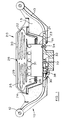
- Figure 1 is a cross-sectional elevation through a steering wheel/air bag module formed in accordance with the present invention;
- Figure 2 is a plan view of the arming mechanism used in the embodiment illustrated in Figure 1; and
- Figure 3 is a section along the line III-III of Figure 2.
- As illustrated in Figure 1, a
steering wheel 10 comprises ofcentral boss 11 with arim 12 supported thereon byarmatures 13. Theboss 11,rim 12 andarmatures 13 are embodied in a resilient foam material and a suitable covering material. A moulded paddedcentral portion 15, which overlays thearmatures 13 is formed centrally of thesteering wheel 10 and provides a location for anair bag module 20. - The
air bag module 20 comprises abacking plate 21 in the form of a dished pressing. Acover 22 is moulded to the outer periphery of thebacking plate 21. Aninflator 23 is mounted centrally of thebacking plate 21 and a support pressing, the outer periphery of which is embedded in themoulded cover 22, surrounds theinflator 23. Anair bag 25 is clamped to the pressing 24 between a pair ofrings 26 and 27, theair bag 25 being folded within the space between the the support pressing 24 and cover 22. Thecover 22 is made of a flexible material, for example rubber, and is formed withgrooves 28 in its inner surface to provide weakened lines, which will split on inflation of theair bag 25 to permit deployment of theair bag 25. Preferably, thegrooves 28 will define twoflat formations groove 28. - The
inflator 23 has a series ofperipheral holes 31 adjacent the end enclosed in theair bag 25, these holes allowing gases generated within theinflator 23 to expand into theair bag 25. The gasses are generated upon fast burn of a pyrotechnic device, when triggered by inertia means. Before the device can be triggered, a spring loadedplunger 32 must be depressed to arm theinflator 23. - The
air bag module 20 is retained within thecentral portion 15 ofsteering wheel 10 by means of threefixing bolts 54 which pass through theboss 11 and engage thebacking plate 21. - An
arming mechanism 30 is secured in a recessed portion of theboss 11. As illustrated in greater detail in Figures 2 and 3, the arming mechanism comprises abase plate 31. Alug 35 is provided on thebase plate 31 centrally of one edge thereof and has a threadedaperture 36 in which is located a correspondingly threadedportion 37 of anarming screw 38. The other end of thearming screw 38 has ashank portion 39 which slidingly locates through anaperature 40 in abracket 41 secured adjacent the opposite edge of thebase plate 31. The end of theshank portion 39 has acircumferential chamfer 42. - A
slide 45 is located between thelug 35 andbracket 41 by means of a pair ofrivets 46, saidrivets 46 engaging inelongated holes 47 in theslide 45, thereby permitting movement of theslide 45 transverse to the axis of thearming screw 38. Aspring element 50 is located on aboss 51 on thebase plate 31 and acts against aflange formation 52 on theslide 45, to urge theslide 45 from one side of thearming screw 38 towards the other. Thebase plate 31 has acutaway portion 53 on said other side of thearming screw 38. - Intermediate of the threaded
portion 37 andshank portion 39, thearming screw 38 has an enlargeddiameter portion 55 adjacent threadedportion 37 and acollar 56 separated from theportion 55 by a circumferentialgrooved portion 57. Thecollar 56 while being of greater diameter than theshank portion 39 is smaller in diameter than theportion 55. Thegrooved portion 57 is slightly wider than the thickness of theflange formation 52 and is of the same diameter as theshank portion 39. - The
flank formation 52 is generally of a height slightly less than the separation between thebase plate 31 and the bottom ofgroove 57 onarming screw 38. Theend portion 60 offlange formation 52 is however of reduced height, so that this portion is a clearance fit between thebase plate 31 and the periphery ofcollar 56. A partspherical recess 62 is also provided in theflange formation 52 at a position which will be aligned with the axis of thearming screw 38, when theslide 45 is hard over to the right, said recess 62 providing a clearance for the enlargeddiameter portion 55 of thearming screw 38. - A
cover plate 65 is pivotally attached to thebase plate 31 along the edgeadjacent bracket 41 on the opposite side of thebase plate 31 to thearming screw 38. Thecover plate 65 has aflange formation 66 which when thecover plate 65 is closed will overly thelug 35 to prevent access to thearming screw 38. Alip formation 67 onflange formation 66 is adapted to engage a complimentary formation on thesteering wheel 10 to retain thecover plate 65 in the closed position. - The
arming mechanism 30 is adpated to be mounted with thecover 65 outermost, to the rear side of theboss 11, thecutaway portion 53 ofbase plate 31 overlying one of thefixing bolts 54 and thearming screw 38 being radially aligned with theplunger 32 ofinflator 23. - With the arming mechanism disclosed above, during assembly of the
air bag module 20 into thesteering wheel 11, thearming screw 38 will be fully withdrawn and slide 45 held over to the left as illustrated in Figure 1, thecollar 56 onarming screw 38 engaging theshoulder defining portion 60 offlange formation 52. After the steering wheel has been fastened to the steering column throughboss 11, theair bag module 20 may be secured to the steering wheel, one of thefixing bolts 54 being accessible through thecutaway portion 53 ofbase plate 31. Thearming screw 38 may then be screwed inwardly untilcollar 56 is clear of theflange formation 52 which is then aligned with thecircumferential groove 57, so that theslider 45 can slide past thearming screw 38, under the influence of thespring 50 until theslider 45 overlays thefixing bolt 54. Thearming screw 38 may then be screwed up, thelarger portion 55 engaging inrecess 62 and thechamfered end 42 of thearming screw 38 engaging aninclined face 33 on theplunger 32 thereby depressing theplunger 32 and arming theinflator 23. If thefixing bolt 54 is not first fully tightened, theslide 45 will foulbolt 54 and cannot move fully to the right and hence therecess 62 will not be aligned with thearming screw 38 and abutment ofportion 55 ofarming screw 38 with theflange formation 52 will prevent further tightening of thearming screw 38 and arming of theinflator 23. Theflange formation 66 oncover plate 65 will only clear thearming screw 38 when it is fully tightened and theinflator 23 armed.Cover plate 65 can consequently only be closed when theinflator 23 is armed. If thecover plate 65 is not closed whensteering wheel 10 is rotated, thecover plate 65 will foul the steering column cowl thus providing an audible as well as visual indication that theinflator 23 is not correctly armed. - When the
inflator 23 is armed as described above, engagement ofportion 55 of thearming screw 38 in therecess 62 offlange formation 52 will prevent theslide 45 from being moved. Consequently thefixing bolt 54 cannot be released to remove theair bag modual 20. In order to remove theair bag modual 20, thecover plate 65 must first be opened and thearming screw 38 fully unscrewed thus disarming theinflator 23. When thearming screw 38 is fully unscrewed, theflange formation 52 is aligned withshank portion 39 and is free to move under thearming screw 38. Theslide 45 may then be moved clear of the fasteningbolt 54 and the arming screw tightened by a few turns to bringcollar 56 into alignment withflange formation 52, thereby retainingslide 45 clear of thefixing bolt 54 which may then be released.
Claims (7)
- An air bag restraint system comprising an air bag module (20) adapted to be located centrally of a steering wheel (10) and secured with respect thereto by at least one fastening means (54), said air bag module (20) including an inflator (23) and screw means (38) for arming said inflator (23), characterised in that interlock means (45, 55) is actuated by said screw means (38), said interlock means (45, 55) preventing release of said fastening means (54) until the inflator (23) has been disarmed and providing an indication of whether the inflator (23) is armed or not.
- An air bag restraint system according to Claim 1 characterised in that said interlock means (45, 55) comprises a slide (45) which is movable between a first position in which it is clear of said fastening means (54) and a second position in which it prevents release of said fastening means (54).
- An air bag restraint system according to Claim 2 characterised in that in said second position, the slide (45) overlays said fastening means (54).
- An air bag restraint system according to Claim 2 characterised in that the screw means (38) engages the slide (45) to lock the slide (45) in its second position when the inflator (23) is armed.
- An air bag restraint system according to Claim 4 characterised in that the screw means (38) engages the slide (45) to lock the slide (45) in its first position, when the inflator (23) is disarmed.
- An air bag restraint system according to any one of the preceding claims characterised in that a cover plate (65) is provided to prevent access to said screw means (38) when the inflator (23) is armed.
- An air bag restraint system according to Claim 6 characterised in that a formation (66) on said cover plate (65) engages said screw means (38) when the inflator (23) is disarmed, in order to prevent closure of the cover plate (65).
Priority Applications (1)
| Application Number | Priority Date | Filing Date | Title |
|---|---|---|---|
| EP93201422A EP0565209B1 (en) | 1988-11-01 | 1989-10-05 | Air bag restraint systems |
Applications Claiming Priority (2)
| Application Number | Priority Date | Filing Date | Title |
|---|---|---|---|
| GB8825540 | 1988-11-01 | ||
| GB888825540A GB8825540D0 (en) | 1988-11-01 | 1988-11-01 | Air bag restraint systems |
Related Child Applications (2)
| Application Number | Title | Priority Date | Filing Date |
|---|---|---|---|
| EP93201422A Division EP0565209B1 (en) | 1988-11-01 | 1989-10-05 | Air bag restraint systems |
| EP93201422.8 Division-Into | 1989-10-05 |
Publications (3)
| Publication Number | Publication Date |
|---|---|
| EP0367415A2 EP0367415A2 (en) | 1990-05-09 |
| EP0367415A3 EP0367415A3 (en) | 1991-04-03 |
| EP0367415B1 true EP0367415B1 (en) | 1994-07-06 |
Family
ID=10646120
Family Applications (2)
| Application Number | Title | Priority Date | Filing Date |
|---|---|---|---|
| EP89310221A Expired - Lifetime EP0367415B1 (en) | 1988-11-01 | 1989-10-05 | Air bag restraint systems |
| EP93201422A Expired - Lifetime EP0565209B1 (en) | 1988-11-01 | 1989-10-05 | Air bag restraint systems |
Family Applications After (1)
| Application Number | Title | Priority Date | Filing Date |
|---|---|---|---|
| EP93201422A Expired - Lifetime EP0565209B1 (en) | 1988-11-01 | 1989-10-05 | Air bag restraint systems |
Country Status (5)
| Country | Link |
|---|---|
| US (2) | US4960292A (en) |
| EP (2) | EP0367415B1 (en) |
| JP (1) | JPH02171363A (en) |
| DE (2) | DE68916617T2 (en) |
| GB (1) | GB8825540D0 (en) |
Families Citing this family (64)
| Publication number | Priority date | Publication date | Assignee | Title |
|---|---|---|---|---|
| US5180187A (en) * | 1989-02-18 | 1993-01-19 | Daimler-Benz Ag | Cover for an airbag unit and the process for producing it |
| JPH084364Y2 (en) * | 1989-09-12 | 1996-02-07 | 株式会社東海理化電機製作所 | Airbag safety device |
| US5072628A (en) * | 1989-09-19 | 1991-12-17 | Oki T Jack | Multi function steering mechanism for a motor vehicle |
| JP3003182B2 (en) * | 1990-08-20 | 2000-01-24 | タカタ株式会社 | How to fold the passenger airbag |
| JP2949841B2 (en) * | 1990-11-30 | 1999-09-20 | タカタ株式会社 | Passenger airbag and passenger airbag device |
| US5195774A (en) * | 1990-11-30 | 1993-03-23 | Takata Corporation | Air bag attaching structure |
| DE9106369U1 (en) * | 1991-05-23 | 1991-08-14 | Autoliv Gmbh, 8060 Dachau, De | |
| US5244229A (en) * | 1991-06-14 | 1993-09-14 | Breed Automotive Technology, Inc. | Mechanical crash sensor |
| GB9112921D0 (en) * | 1991-06-14 | 1991-08-07 | Jaguar Cars | Air bag restraint systems |
| US5348340A (en) * | 1991-06-14 | 1994-09-20 | Breed Automotive Technology, Inc. | Air bag assembly for motor vehicles |
| EP0588176B1 (en) * | 1992-09-16 | 1998-12-02 | Toyoda Gosei Co., Ltd. | A pad for use in an air bag device |
| DE4315853C2 (en) * | 1993-05-12 | 1996-05-15 | Ymos Ag Ind Produkte | Dashboard with front passenger airbag |
| GB2282574B (en) * | 1993-10-05 | 1997-01-15 | Autoliv Dev | A steering wheel |
| FR2716857B1 (en) * | 1994-03-03 | 1997-07-18 | Autoliv Dev | Steering wheel with pre-assembled airbag anti-shock protection device. |
| US5419585A (en) * | 1994-04-13 | 1995-05-30 | Breed Automotive Technology, Inc. | Retrofit vehicular steering wheel assembly having an air bag assembly |
| IT236740Y1 (en) * | 1995-03-16 | 2000-08-17 | Momo Spa | MOTOR VEHICLE STEERING WHEEL EQUIPPED WITH AIR CUSHION PROTECTION DEVICE |
| EP0732237A1 (en) * | 1995-03-16 | 1996-09-18 | General Motors Corporation | Steering wheel assembly |
| US5584501A (en) * | 1995-09-15 | 1996-12-17 | Trw Inc. | Vehicle occupant restraint apparatus |
| US5615910A (en) * | 1995-12-14 | 1997-04-01 | Trw Inc. | Apparatus for restraining a driver of a vehicle |
| JPH09169276A (en) * | 1995-12-20 | 1997-06-30 | Toyoda Gosei Co Ltd | Steering column cover |
| US5685559A (en) * | 1996-04-25 | 1997-11-11 | Trw Inc. | Steering wheel with air bag module |
| DE19630819C2 (en) * | 1996-07-31 | 2000-07-20 | Autoliv Dev | Airbag arrangement with clamp fastening of the airbag |
| US5931491A (en) * | 1997-08-28 | 1999-08-03 | Autoliv Asp, Inc. | Airbag module with a reduced number of fasteners |
| DE19901357C1 (en) | 1999-01-15 | 2000-03-09 | Daimler Chrysler Ag | Release prevention method for screw fixing for electrical apparatus e.g. for automobile airbag passenger restraint, uses cover attached to electrical supply plug for blocking access to screw until plug is removed from apparatus housing |
| DE29902274U1 (en) * | 1999-02-09 | 1999-04-15 | Trw Automotive Safety Sys Gmbh | Airbag for a motor vehicle airbag module |
| US6834218B2 (en) | 2001-11-05 | 2004-12-21 | Ford Global Technologies, Llc | Roll over stability control for an automotive vehicle |
| JP2001213259A (en) * | 2000-02-03 | 2001-08-07 | Toyoda Gosei Co Ltd | Steering wheel having air-bag system |
| US6276711B1 (en) * | 2000-03-27 | 2001-08-21 | Breed Automotive Technology, Inc. | Quick disconnect feature for snap-in driver air bag module |
| DE10030471C1 (en) | 2000-06-21 | 2001-07-26 | Bosch Gmbh Robert | Automobile airbag module has mechanical locking device and electrical contact device for connecting gas generator detonation device to control device |
| US7132937B2 (en) | 2000-09-25 | 2006-11-07 | Ford Global Technologies, Llc | Wheel lift identification for an automotive vehicle using passive and active detection |
| US6356188B1 (en) | 2000-09-25 | 2002-03-12 | Ford Global Technologies, Inc. | Wheel lift identification for an automotive vehicle |
| US6904350B2 (en) | 2000-09-25 | 2005-06-07 | Ford Global Technologies, Llc | System for dynamically determining the wheel grounding and wheel lifting conditions and their applications in roll stability control |
| US7233236B2 (en) | 2000-09-25 | 2007-06-19 | Ford Global Technologies, Llc | Passive wheel lift identification for an automotive vehicle using operating input torque to wheel |
| US7109856B2 (en) | 2000-09-25 | 2006-09-19 | Ford Global Technologies, Llc | Wheel lifted and grounded identification for an automotive vehicle |
| US6654674B2 (en) | 2001-11-21 | 2003-11-25 | Ford Global Technologies, Llc | Enhanced system for yaw stability control system to include roll stability control function |
| US6556908B1 (en) | 2002-03-04 | 2003-04-29 | Ford Global Technologies, Inc. | Attitude sensing system for an automotive vehicle relative to the road |
| US7194351B2 (en) | 2002-08-01 | 2007-03-20 | Ford Global Technologies, Llc | System and method for determining a wheel departure angle for a rollover control system |
| US7003389B2 (en) | 2002-08-01 | 2006-02-21 | Ford Global Technologies, Llc | System and method for characterizing vehicle body to road angle for vehicle roll stability control |
| US6941205B2 (en) | 2002-08-01 | 2005-09-06 | Ford Global Technologies, Llc. | System and method for deteching roll rate sensor fault |
| US7085639B2 (en) | 2002-08-01 | 2006-08-01 | Ford Global Technologies, Llc | System and method for characterizing the road bank for vehicle roll stability control |
| US7302331B2 (en) | 2002-08-01 | 2007-11-27 | Ford Global Technologies, Inc. | Wheel lift identification for an automotive vehicle |
| US20040024504A1 (en) | 2002-08-05 | 2004-02-05 | Salib Albert Chenouda | System and method for operating a rollover control system during an elevated condition |
| US7430468B2 (en) | 2002-08-05 | 2008-09-30 | Ford Global Technologies, Llc | System and method for sensitizing the activation criteria of a rollover control system |
| US7085642B2 (en) | 2002-08-05 | 2006-08-01 | Ford Global Technologies, Llc | Method and system for correcting sensor offsets |
| US6963797B2 (en) | 2002-08-05 | 2005-11-08 | Ford Global Technologies, Llc | System and method for determining an amount of control for operating a rollover control system |
| US20040024505A1 (en) | 2002-08-05 | 2004-02-05 | Salib Albert Chenouda | System and method for operating a rollover control system in a transition to a rollover condition |
| US6961648B2 (en) | 2002-08-05 | 2005-11-01 | Ford Motor Company | System and method for desensitizing the activation criteria of a rollover control system |
| US7653471B2 (en) | 2003-02-26 | 2010-01-26 | Ford Global Technologies, Llc | Active driven wheel lift identification for an automotive vehicle |
| US9162656B2 (en) | 2003-02-26 | 2015-10-20 | Ford Global Technologies, Llc | Active driven wheel lift identification for an automotive vehicle |
| US7239949B2 (en) | 2003-02-26 | 2007-07-03 | Ford Global Technologies, Llc | Integrated sensing system |
| US7185915B2 (en) * | 2003-02-27 | 2007-03-06 | Toyoda Gosei Co., Ltd. | Steering wheel incorporating air bag device |
| JP2004314837A (en) * | 2003-04-17 | 2004-11-11 | Takata Corp | Handle cover and motorcycle |
| US7136731B2 (en) | 2003-06-11 | 2006-11-14 | Ford Global Technologies, Llc | System for determining vehicular relative roll angle during a potential rollover event |
| US7308350B2 (en) | 2004-05-20 | 2007-12-11 | Ford Global Technologies, Llc | Method and apparatus for determining adaptive brake gain parameters for use in a safety system of an automotive vehicle |
| US7451032B2 (en) | 2004-06-02 | 2008-11-11 | Ford Global Technologies, Llc | System and method for determining desired yaw rate and lateral velocity for use in a vehicle dynamic control system |
| US7640081B2 (en) | 2004-10-01 | 2009-12-29 | Ford Global Technologies, Llc | Roll stability control using four-wheel drive |
| US7668645B2 (en) | 2004-10-15 | 2010-02-23 | Ford Global Technologies | System and method for dynamically determining vehicle loading and vertical loading distance for use in a vehicle dynamic control system |
| US7715965B2 (en) | 2004-10-15 | 2010-05-11 | Ford Global Technologies | System and method for qualitatively determining vehicle loading conditions |
| US7660654B2 (en) | 2004-12-13 | 2010-02-09 | Ford Global Technologies, Llc | System for dynamically determining vehicle rear/trunk loading for use in a vehicle control system |
| US7480547B2 (en) | 2005-04-14 | 2009-01-20 | Ford Global Technologies, Llc | Attitude sensing system for an automotive vehicle relative to the road |
| US7590481B2 (en) | 2005-09-19 | 2009-09-15 | Ford Global Technologies, Llc | Integrated vehicle control system using dynamically determined vehicle conditions |
| KR100657662B1 (en) * | 2005-10-06 | 2006-12-14 | 기아자동차주식회사 | An apparatus for mounting driver side air bag module in vehicle |
| US7600826B2 (en) | 2005-11-09 | 2009-10-13 | Ford Global Technologies, Llc | System for dynamically determining axle loadings of a moving vehicle using integrated sensing system and its application in vehicle dynamics controls |
| US8121758B2 (en) | 2005-11-09 | 2012-02-21 | Ford Global Technologies | System for determining torque and tire forces using integrated sensing system |
Family Cites Families (6)
| Publication number | Priority date | Publication date | Assignee | Title |
|---|---|---|---|---|
| US4167276A (en) * | 1976-12-17 | 1979-09-11 | Allied Chemical Corporation | Self-contained air bag system |
| DE3234422A1 (en) * | 1982-09-16 | 1984-03-22 | Repa Feinstanzwerk Gmbh, 7071 Alfdorf | Switching device for safety devices, preferably for motor vehicles |
| US4666182A (en) * | 1984-02-15 | 1987-05-19 | Breed Corporation | Non crush zone-all mechanical damped sensor |
| US4580810A (en) * | 1984-02-15 | 1986-04-08 | Breed Corporation | Air bag system |
| JPH07115624B2 (en) * | 1987-03-25 | 1995-12-13 | 本田技研工業株式会社 | Air bagging device for vehicles |
| JPH082749B2 (en) * | 1987-09-29 | 1996-01-17 | 本田技研工業株式会社 | Vehicle collision detector |
-
1988
- 1988-11-01 GB GB888825540A patent/GB8825540D0/en active Pending
-
1989
- 1989-10-05 DE DE68916617T patent/DE68916617T2/en not_active Expired - Lifetime
- 1989-10-05 EP EP89310221A patent/EP0367415B1/en not_active Expired - Lifetime
- 1989-10-05 EP EP93201422A patent/EP0565209B1/en not_active Expired - Lifetime
- 1989-10-05 DE DE68923185T patent/DE68923185T2/en not_active Expired - Lifetime
- 1989-10-11 US US07/420,142 patent/US4960292A/en not_active Expired - Fee Related
- 1989-10-23 JP JP1275759A patent/JPH02171363A/en active Pending
-
1990
- 1990-10-01 US US07/591,543 patent/US5046757A/en not_active Expired - Lifetime
Also Published As
| Publication number | Publication date |
|---|---|
| US4960292A (en) | 1990-10-02 |
| JPH02171363A (en) | 1990-07-03 |
| EP0367415A3 (en) | 1991-04-03 |
| US5046757A (en) | 1991-09-10 |
| DE68916617D1 (en) | 1994-08-11 |
| DE68923185T2 (en) | 1995-10-26 |
| DE68916617T2 (en) | 1995-01-19 |
| EP0565209B1 (en) | 1995-06-21 |
| GB8825540D0 (en) | 1988-12-07 |
| EP0367415A2 (en) | 1990-05-09 |
| DE68923185D1 (en) | 1995-07-27 |
| EP0565209A1 (en) | 1993-10-13 |
Similar Documents
| Publication | Publication Date | Title |
|---|---|---|
| EP0367415B1 (en) | Air bag restraint systems | |
| US3495675A (en) | Vehicle safety method and apparatus using expandable confinement | |
| EP0376564B1 (en) | Airbag module and method of making same | |
| CA1047565A (en) | Inflator for vehicle occupant restraint system | |
| US6565113B2 (en) | Air bag module | |
| US5520410A (en) | Door locking mechanism for air bag module | |
| US5235146A (en) | Steering wheel horn switch arrangement | |
| US5829777A (en) | Air bag device | |
| US5816611A (en) | Arrangement for disconnecting a vehicle airbag | |
| US6736425B2 (en) | System for venting an air bag module | |
| GB2157043A (en) | Air bag systems | |
| EP0720542B1 (en) | A vehicle steering wheel arrangement | |
| US5520409A (en) | Cover retention in occupant restraint installations | |
| EP0560355A1 (en) | Air bag module | |
| US5806883A (en) | Steering wheel and air bag module | |
| EP1507685B1 (en) | Airbag module with controlled venting | |
| US4818029A (en) | Vehicle anti-theft device making at least one wheel unserviceable, and a wheel comprising the device | |
| US5348340A (en) | Air bag assembly for motor vehicles | |
| US5527065A (en) | Depolyment door for use in a vehicle occupant restraint apparatus | |
| US5566975A (en) | Controlled pressure relief of an inflatable restraint reaction canister | |
| US5209520A (en) | Air bag restraint systems | |
| JP3671490B2 (en) | Airbag device for driver's seat | |
| JP4757913B2 (en) | Airbag module | |
| US5931490A (en) | Integrated steering wheel and airbag module | |
| GB2318101A (en) | Horn switch and airbag retaining ring arrangement |
Legal Events
| Date | Code | Title | Description |
|---|---|---|---|
| PUAI | Public reference made under article 153(3) epc to a published international application that has entered the european phase |
Free format text: ORIGINAL CODE: 0009012 |
|
| AK | Designated contracting states |
Kind code of ref document: A2 Designated state(s): DE FR GB IT SE |
|
| PUAL | Search report despatched |
Free format text: ORIGINAL CODE: 0009013 |
|
| AK | Designated contracting states |
Kind code of ref document: A3 Designated state(s): DE FR GB IT SE |
|
| 17P | Request for examination filed |
Effective date: 19910917 |
|
| 17Q | First examination report despatched |
Effective date: 19921207 |
|
| GRAA | (expected) grant |
Free format text: ORIGINAL CODE: 0009210 |
|
| AK | Designated contracting states |
Kind code of ref document: B1 Designated state(s): DE FR GB IT SE |
|
| XX | Miscellaneous (additional remarks) |
Free format text: TEILANMELDUNG 93201422.8 EINGEREICHT AM 05/10/89. |
|
| REF | Corresponds to: |
Ref document number: 68916617 Country of ref document: DE Date of ref document: 19940811 |
|
| ET | Fr: translation filed | ||
| PGFP | Annual fee paid to national office [announced via postgrant information from national office to epo] |
Ref country code: SE Payment date: 19940916 Year of fee payment: 6 |
|
| ITF | It: translation for a ep patent filed |
Owner name: JACOBACCI CASETTA & PERANI S.P.A. |
|
| EAL | Se: european patent in force in sweden |
Ref document number: 89310221.0 |
|
| PLBE | No opposition filed within time limit |
Free format text: ORIGINAL CODE: 0009261 |
|
| STAA | Information on the status of an ep patent application or granted ep patent |
Free format text: STATUS: NO OPPOSITION FILED WITHIN TIME LIMIT |
|
| 26N | No opposition filed | ||
| PG25 | Lapsed in a contracting state [announced via postgrant information from national office to epo] |
Ref country code: SE Effective date: 19951006 |
|
| REG | Reference to a national code |
Ref country code: GB Ref legal event code: 746 Effective date: 19950920 |
|
| EUG | Se: european patent has lapsed |
Ref document number: 89310221.0 |
|
| PGFP | Annual fee paid to national office [announced via postgrant information from national office to epo] |
Ref country code: GB Payment date: 19960926 Year of fee payment: 8 |
|
| PGFP | Annual fee paid to national office [announced via postgrant information from national office to epo] |
Ref country code: FR Payment date: 19961011 Year of fee payment: 8 |
|
| PGFP | Annual fee paid to national office [announced via postgrant information from national office to epo] |
Ref country code: DE Payment date: 19961021 Year of fee payment: 8 |
|
| REG | Reference to a national code |
Ref country code: FR Ref legal event code: D6 |
|
| PG25 | Lapsed in a contracting state [announced via postgrant information from national office to epo] |
Ref country code: GB Free format text: LAPSE BECAUSE OF NON-PAYMENT OF DUE FEES Effective date: 19971005 |
|
| PG25 | Lapsed in a contracting state [announced via postgrant information from national office to epo] |
Ref country code: DE Effective date: 19971014 |
|
| PG25 | Lapsed in a contracting state [announced via postgrant information from national office to epo] |
Ref country code: FR Free format text: THE PATENT HAS BEEN ANNULLED BY A DECISION OF A NATIONAL AUTHORITY Effective date: 19971031 |
|
| GBPC | Gb: european patent ceased through non-payment of renewal fee |
Effective date: 19971005 |
|
| REG | Reference to a national code |
Ref country code: FR Ref legal event code: ST |
|
| PG25 | Lapsed in a contracting state [announced via postgrant information from national office to epo] |
Ref country code: IT Free format text: LAPSE BECAUSE OF NON-PAYMENT OF DUE FEES;WARNING: LAPSES OF ITALIAN PATENTS WITH EFFECTIVE DATE BEFORE 2007 MAY HAVE OCCURRED AT ANY TIME BEFORE 2007. THE CORRECT EFFECTIVE DATE MAY BE DIFFERENT FROM THE ONE RECORDED. Effective date: 20051005 |