EP0367377A2 - System and method for producing discrimination nets for expert systems - Google Patents
System and method for producing discrimination nets for expert systems Download PDFInfo
- Publication number
- EP0367377A2 EP0367377A2 EP89307388A EP89307388A EP0367377A2 EP 0367377 A2 EP0367377 A2 EP 0367377A2 EP 89307388 A EP89307388 A EP 89307388A EP 89307388 A EP89307388 A EP 89307388A EP 0367377 A2 EP0367377 A2 EP 0367377A2
- Authority
- EP
- European Patent Office
- Prior art keywords
- satisfied
- expression
- nodes
- data
- network
- Prior art date
- Legal status (The legal status is an assumption and is not a legal conclusion. Google has not performed a legal analysis and makes no representation as to the accuracy of the status listed.)
- Withdrawn
Links
Images


Classifications
-
- G—PHYSICS
- G06—COMPUTING; CALCULATING OR COUNTING
- G06N—COMPUTING ARRANGEMENTS BASED ON SPECIFIC COMPUTATIONAL MODELS
- G06N5/00—Computing arrangements using knowledge-based models
- G06N5/04—Inference or reasoning models
- G06N5/046—Forward inferencing; Production systems
- G06N5/047—Pattern matching networks; Rete networks
Definitions
- This invention relates to rule-based artificial intelligence systems (i.e., so-called "expert systems") in which the various conditions defined by the rules are structured as a discrimination net to allow efficient determination of which rules are applicable to data obtained by the system.
- expert systems i.e., so-called "expert systems”
- An expert system is based on a computer program which comprises a set of rules and defines types of data that will be processed according to the rules.
- the system performs matching between rules and data in a working data base that is obtained by the system from a user or from other data bases to determine which rules apply, and one or more of these rules is "fired” (i.e., applied to the data) to change the data in the working data base, provide advice to the user or explanations in response to the user's questions, or to take some other action.
- the inference process is repeated until no rules are found to be applicable to the data, or the firing of rules no longer produces a result.
- Each rule includes one or more conditions (collectively referred to as the "left-hand side" of the rule) which, if satisfied by the data, indicate that the rule is applicable.
- the operations to be performed when the rule is fired are listed in the "right-hand side” of the rule.
- One way to determine which rules are applicable is to test every condition in the left hand sides of all of the rules each time a new element of data is obtained by the system. With this scheme, conditions that are found satisfied (or not satisfied) by data in the working data base are retested each time the working data base is altered by addition or deletion of data, even if the altered data could not possibly have changed the result of the test. Also, often the same condition is found in the left-hand side of more than one rule, and thus is tested multiple times whenever a new data element is obtained.
- RETE-net more efficiently determines which rules are applicable by testing, when the working data base is changed, only those conditions having results that may have changed in response to the changed data in the working data base. Also, RETE-nets cause conditions that are common to more than one rule to be tested only once each time the working data base changes.
- a RETE-net is a data structure in which the conditions of all rules are arranged as a network of nodes.
- the conditions of the rules are identified by test nodes that are interconnected by a set of join nodes to represent the various combinations of conditions that are specified in the left-hand sides of the rules.
- a condition is represented by a single test node, even if that condition occurs in the left-hand sides of multiple rules.
- Tokens that represent data in the working data base are passed via the nodes through the RETE-net as the data pass various tests and combinations of tests.
- the RETE-net terminates at result nodes that each correspond to an individual rule. If the left-hand side of a rule is satisfied, the RETE-net stores a token in the result node corresponding to that rule.
- RETE-nets work well when the combinations of conditions in the left-hand side of a rule are of the kind that can easily be represented as such a network of nodes.
- a rule left-hand side that requires condition 1 AND condition 2 AND condition 3 AND condition 4 to be satisfied is represented with an AND node joining the test nodes for conditions 1 and 2, another AND node joining the first AND node and the condition 3 test node, and a third AND node joining the second AND node and the test node for condition 4.
- condition 1 AND at least 2 of: conditions 2, 3, 4, or 5
- metal-tests are typically represented by a complex set of nodes which join the condition 1 test node with permutations of the test nodes for conditions 2, 3, 4, and 5, and which terminate at several different result nodes.
- RETE-net-based expert system programs typically attempt to identify the missing data with special rules that cause the inference process to proceed in the reverse direction (i.e., "backward chaining"), or by asking the user a limited series of questions.
- the expert system program may be augmented with special rules (called “null condition” rules) that have conditions which are always satisfied and that are fired only if the left-hand side of no other rule is satisfied. The "actions" taken by null condition rules are selected to help the user recognize that data is needed and to provide a guide for identifying the missing data
- an expression comprising conditions is evaluated based on values of data elements presented to a network of a kind in which the conditions are represented by nodes and the relationships among conditions in the expression are represented by links among the nodes, by storing information that identifies which conditions represented by at least some of the nodes have been satisfied by the values of the data elements, and testing the stored information in accordance with the expression as a basis for evaluating said expression.
- Preferred embodiments include the following features.
- the information is stored in separate locations assigned to information from different nodes, and the information from each node is entered into the location assigned to that node.
- the expression is satisfied if a predetermined number of the conditions in the expression have been satisfied, and the number of locations that are occupied with information are counted to determine how many conditions have been satisfied.
- the expression includes an indexing condition represented by a node, and groups of the locations are established in storage based on information from the indexing condition node, with each group being associated with the data elements that satisfy the indexing condition.
- the information from the nodes identifies the data elements that satisfy the indexing condition and is entered in the locations of the group that corresponds to the identified data elements.
- the number of locations in each group that are occupied with information from the nodes are counted to determine whether the expression is satisfied.
- Each group is monitored to determine whether the group currently has a count of occupied locations that indicates that the expression is satisfied. Occupied locations in a group are counted each time a new entry of information is made in that group.
- the expression is indicated to be satisfied if a new entry of information causes a group that did not previously have a count of occupied locations that indicated satisfaction of the expression to have a count of occupied locations that indicates that the expression is satisfied. But the indication is not made if the group already had a count of occupied locations that satisfied the expression at the time that the new entry is made into the group
- Some nodes are adapted to cause the information to be deleted from corresponding occupied locations in storage, and the occupied locations in a group are counted each time that information is deleted from a location in that group. An indication is made that the expression is not satisfied if a deletion of information causes a group that previously had a count of occupied locations that satisfied the expression to have a count of occupied locations that does not satisfy the expression.
- the network which is preferably a discrimination net, such as a reticular net (i.e., a RETE-net), efficiently represent expressions, such a meta-tests, that are satisfied by a combination of some, but less than all, of the conditions in the expressions.
- a meta-tests include expressions that are satisfied if any one of the conditions are satisfied, or if at least (or at most) a predetermined number of the conditions are satisfied.
- the network enables results of the evaluation to be available at a single location (e.g., in a terminal node in the RETE-net), thereby facilitating a determination of whether the expression is satisfied.
- the invention features evaluating an expression that comprises conditions which pertain to possible values of data belonging to categories of data based on actual values of data presented to a network of a kind in which the conditions are represented by nodes, by identifying a category of data for which values need not occur in the network in order for a condition that requires a value in the category to be provisionally satisfied, and causing the node that represents the condition to indicate that the condition is provisionally satisfied even when no values in the identified category occur in the network.
- Preferred embodiments include the following features.
- the category is identified by assigning to it a predetermined value, which is maintained until a value belonging to that category has occurred in the network.
- Each node having a condition that tests for a value in the identified category tests, if the condition is not satisfied, whether the category has the predetermined value and, if so, the node indicates that the condition is provisionally satisfied.
- the expression is deemed to have been satisfied if a predetermined combination of nodes indicate that the conditions represented by the nodes are satisfied or are provisionally satisfied, and, if the expression is satisfied, the number of conditions that are indicated to be provisionally satisfied are identified.
- the expression is associated with a rule, and the rule is fired if the number of conditions that are indicated to be provisionally satisfied is zero.
- the expressions are each associated with a rule, and one rule is selected based on the priority determination.
- the selected rule is fired if the number of conditions that are indicated to be provisionally satisfied for the satisfied expression that is associated with the selected rule equals zero. On the other hand, if the number of conditions that are indicated to be provisionally satisfied is more than zero, the identified category of data for which no values occur in the network is selected, and a value for the selected category of data is obtained.
- categories for which data are missing are efficiently identified by a mechanism that is invisible to the user. No special rules, null condition rules, or backward chaining is required. Thus, the missing data can easily be retrieved, either by the user or by running a separate program.
- expert system 10 executes an expert system program 12 created using any suitable expert system programming language (such as OPS5, available from Digital Equipment Corporation).
- Expert system program 12 includes a set of data definitions 14 that identify categories of data which program 12 will use during operation. For example, if program 12 is to be used with data concerning people, data definitions 14 might include categories such as name, age, sex, height, and weight.
- Program 12 also includes a set of rules, described by rule definitions 16, for manipulating actual data that fit definitions 14 and that are obtained by system 10.
- Expert system program 12 also includes links to programs 18 in other languages (such as C, Fortran, Basic, etc.) for performing tasks (e.g., accessing remote databases, making statistical computations) when called upon during the execution of expert system program 12.
- a set of rules 20 each includes one or more conditions or tests 22 (e.g., tests T1-T4) that are joined by test connectors 24 (e.g., "ANDs") to form an expression known as the left hand side 26 of the rule.
- a rule 20 is applicable to the data obtained by system 10 only if the data satisfies the expression of tests 22, 24 in the left hand side 26 of that rule.
- rule 1 is applicable only if the data passes tests T1, T2, and T3 (i e., only if tests T1-T3 are all "true”).
- Test T2 is also in the left-hand side 26 of rule 2 and must be true along with test T4 for rule 2 to be applicable.
- tests T1, T3, and T4 all must be true for left-hand side 26 of rule 3 to be satisfied
- each rule 20 contains an "action list" 30 that is executed if the rule is fired.
- the firing of a rule might cause system 10 to obtain more data or compute the value of some data (for example, by executing one of other programs 18).
- a rule firing may also cause some external action to be taken (such as displaying data or changing an external database 48).
- data definitions 14 and rule definitions 16 are compiled by a compiler 32 in a manner described in detail below and stored in a memory 33 of an inference engine 34 as a type of discrimination net data structure known as a reticular net 36 (i.e., a RETE-net).
- a reticular net 36 i.e., a RETE-net
- the other programs 18 are compiled by their own compilers 33 and applied to processor and controller 46 in inference engine 34.
- test T1-T4 are each represented by a single test node 40a-40d, respectively, regardless of how many rules the tests 22 appear in.
- test T1 is represented by a single test node 40a, even though test T1 appears in the left-hand sides 26 of both rules 1 and 3.
- Test nodes 40a-40d are fed by a common start node 38 in a manner described in detail below.
- the outputs of test nodes 40a-40d are interconnected through a set of join nodes 42a-42e to a set of result or terminal nodes 44a-44c.
- Join nodes 42a-42e represent the function (in this case, "ANDs") of the test connectors 24 in the left-hand sides 26 of rules 20 (Fig. 2).
- Each terminal node 44a-44c is associated with the left-hand side 26 of one of rules 20.
- the path from start node 38 through test nodes 40a-40d and join nodes 42a-42e to each terminal node 44a-44c represents the test expression in the left-hand side 26 of one of rules 20.
- the outputs of test nodes 40a and 40b are interconnected by AND join node 42a, the output of which is in turn interconnected with the output of test node 40c in AND join node 42b.
- the result, applied to terminal node 44a represents the test expression [(T1) AND (T2) AND (T3)] which comprises the left-hand side 26 of rule 1.
- test nodes 40b and 40d are combined in AND join node 42c and the result applied to terminal node 44b as a representation of the expression [(T2) AND (T4)] specified in the left-hand side 26 of rule 2.
- expression in the left-hand side of rule 3, namely [(T1) AND (T3) AND (T4)] is represented in RETE-net 36 by the interconnection of the outputs of test nodes 40a and 40c with AND join node 42d, the output of which is joined with the output oftest node 40d in AND join node 42e and applied to terminal node 44c.
- each terminal node 44a-44c identifies the action list 30 of the rule with which the terminal node is associated. For example, terminal node 44a identifies the action list 30 of rule 1.
- a processor/controller 46 in inference engine 34 obtains working data in a variety of ways, for example, from data base 48 or the user via a user interface 50, by performing initial computations specified by data definitions 14, or by executing right hand sides 28 of rules 20 (Fig 2).
- Processor/controller 46 stores this data in a working memory 54 as a set of data elements 56.
- a data element 56 identifies one or more data definitions and a value for each definition.
- a data element 56 could comprise one category (e.g., age) and an associated value, or a number of categories (e.g., name, age, height, sex, and weight) and a data value for each category.
- processor/controller 46 In operation, whenever new data elements 56 are stored in working memory 54, processor/controller 46 creates "add" tokens for them and applies the tokens one at a time to RETE-net 36, which processes the tokens to determine if one or more rules 20 are applicable to the data stored in working memory 54. This process is known as "matching" and is described in detail below. If multiple rules 20 are applicable, or if a single rule is applicable to more than one combination of data elements, processor/controller 46 performs conflict resolution to select one or more of such rule "instances", and fires those rule instances.
- the firing of a rule instance may cause several results. For example, it may create new data or cause processor/controller 46 to calculate a new value for existing data or to obtain more data, either from data base 48 or from the user via interface 50.
- Processor/controller 46 stores any newly acquired data as elements 56 in working memory 54, creates add tokens for these new data elements, and applies the new add tokens to RETE-net 36 in another inference cycle to find a rule instance for firing.
- processor/controller 46 applies a "delete" token representing the old data value to RETE-net 36, and then applies an "add” token for the new data value. This process continues until no applicable rules are identified or until no new data elements 56 are generated or obtained as the result of firing the rules.
- processor/controller 46 via interface 50, can provide advice to the user or explanations to questions from the user.
- Processor/controller 46 can also take other actions, such as executing one or more of programs 18 or displaying data to the user
- processor/controller 46 applies add or delete tokens t representing data elements 56 (called primitive tokens) to start node 38, and then in turn to test nodes 40a-40d.
- Processor/controller 46 performs the test identified by each test node 40a-40d on the data associated with the primitive token t and, if the test passes, processor/controller 46 sends the primitive token to the appropriate join node or nodes 42a-42e.
- the primitive tokens that are sent from test nodes 40a-40d are designated t1 ⁇ t4, respectively, in Fig. 3, although they are identical to the token t.
- Each join node 42a-42e (e.g., AND join node 42a, shown in detail in Fig. 3) includes a pair of memories, one each for the nodes from which the join node receives tokens.
- join node 42a includes left memory 52 for receiving and storing tokens t1 from test node 40a, and a right memory 54 to receive and store tokens t2 from test node 40b.
- Join nodes define a wide variety of possible functions that correspond to the functions of the test connectors 26 in the rules (Fig. 2).
- join nodes can specify a simple logical ANDing of tokens in left memory 52 with tokens in right memory 54. (This is in fact the function of join nodes 42a-42e.)
- a join node (called a NOT join node) can specify a check for the absence of tokens in right memory 54 in conjunction with the presence of tokens in left memory 52.
- Join nodes can also identify tests on the data elements associated with the input tokens to allow processor/controller 46 to determine, for example, whether a data element associated with one token is equal to, not equal to, less than, greater than, less than or equal to, or greater than or equal to the data element associated with the other token.
- the programmer can also specify other tests to be performed by processor/controller 46on the data elements at the join nodes.
- processor/controller 46 when a token match is found, processor/controller 46 generates a new token, called a complex token, which identifies which tokens (and hence which data elements) were matched at the join node. Processor/controller 46 sends the complex token to the next node in RETE-net 36.
- complex tokens can be add tokens or delete tokens.
- Complex token t2-t1 identifies both primitive tokens t1 and t2 and thus also identifies data elements A, B that have passed test T1 and T2 and have satisfied the function of join node 42a.
- Processor/ controller 46 sends an add token t3 which represents data element C from test node 40c to right memory 54 of ANT join node 42b. A match thus exists between primitive token t3 and the t2-t1 complex token already stored in left memory 52 of node 42b. Processor/controller 46 produces another complex add token, t3-t2-t1, identifying primitive tokens t3, t2, t1, (and thus data elements C, B, and A, respectively).
- Complex add token t3-t2-t1 is stored by processor/controller 46 in terminal node 44a and indicates that the left-hand side 26 of rule 1 is satisfied. Similarly, whenever the processing of a new data element 56 causes the left-hand side 26 of rule 2 to be satisfied, processor/controller 46 stores a complex add token t4-t2 in terminal node 44b from join node 46c. Also, when tests T1, T3, and T4 in the left-hand side of rule 3 are satisfied, complex add token t4-t3-t1 is stored in terminal node 44c from join node 42e by processor/controller 46.
- processor/controller 46 After tokens representing all of the data elements 56 have been applied to RETE-net 36, processor/controller 46 checks terminal nodes 44a-44c to determine which rule left-hand sides 26 are satisfied, and which data elements satisfy the left-hand side or sides. It is possible that the left-hand sides 26 of multiple rules 20 (e.g., rules 1 and 2) are satisfied. It is also possible that the left-hand side 26 of a single rule (e.g , rule 1) is satisfied by more than one combination of data elements 56. For example, if test T3 is also satisfied by data element D, a pair of complex t3-t2-t1 add tokens identifying data elements D, B, and A and data elements C, B, and A, respectively, will be present atterminal node 44a.
- Each combination of data elements 56 that satisfies a rule left-hand side 26 identifies an "instance" of the rule 1, that is, defines a set of data elements 56 for which a rule is applicable.
- Inference engine 34 performs conflict resolution between multiple instances of rules to determine which one or more instances of which rule or rules to fire.
- processor/controller 46 marks as deleted the complex add token in the terminal node (e.g., token t3-t2-t1 (for data elements C, B, A) in node 44a) associated with that instance, so that this rule is not considered satisfied again until another complex token is stored in node 44a (or unless more than one complex token was stored in node 44a when rule 1 was fired).
- start node 38, test nodes 40a-40d, join nodes 42a-42e, and terminal nodes 44a-44c are defined by data structures 60, 70, 80, and 90, respectively, stored in inference engine 34.
- the data structure 60 of start node 38 is shown in Fig. 4 and includes a field 62 which holds a pointer to a list of pointers which contain the addresses of successor nodes in RETE-net 36, that is, the addresses 71 (Fig. 5) of test nodes 40a-40d.
- the data structure 70 of test noted 40a-40d includes field 72 which is a pointer that contains the memory address of the test assigned to the test node (i e., test T1 for node 40a).
- Field 73 contains a pointer to a list of pointers that hold the addresses of the left memories 52 (Fig. 3) of the node or nodes to which tokens are sent from the test node 40a-40d.
- field 73 for test node 40b holds a pointer to a list containing a pointer that holds the address of left memory (LM) 52 of join node 42c.
- Field 74 holds a pointer to a list of pointers that contain the addresses of the right memories 54 of the successor node or nodes to which tokens are sent.
- field 74 for test node 40b holds a list that comprises a pointer to a list that comprises a pointer that contains the address of right memory (RM) 54 of join node 42a.
- the data structure 80 of join nodes 42a-42e includes a field 82 that contains a pointer to the address of the left memory (LM) 52 of the join node, and a pointer to the right memory (RM) 54 address of the node is held in field 83.
- a pointer in field 84 designates the location in the memory 33 of inference engine 34 of the test (e.g., equal to, not equal to, less than, greater than, less than or equal to, greater than or equal to, or don't care) and logical function (e.g., AND or NOT) identified by the node to match left memory and right memory tokens.
- tokens are passed from join nodes 42a-42e only to left memories 52 of successor nodes.
- Field 85 contains a pointer to a list of pointers that contain these left memory addresses.
- field 85 in the data structure 80 of join node 42a contains a pointer to the address of the left memory 52 of join node 42b .
- the data structure 90 for terminal nodes 44a-44c includes a field 92 that contains a pointer to a list of pointers that contain the locations in the memory 33 of inference engine 34 where one or more complex tokens received from the join nodes are stored.
- field 92 for node 44a contains a pointer to a location in memory where complex tokens t3-t2-t1 from join node 42b are stored.
- the addresses 91 of terminal nodes 44a-44c are identified by pointers in fields 85 of the data structures 80 of join nodes 42b, 42c, 42e, respectively.
- Field 93 contains a pointer to the location in inference engine memory 33 in which the action list 30 of the rule identified by the terminal node 44a-44c is stored.
- the data structure 100 of a primitive token includes field 102 that holds a pointer to the location in working memory 54 at which the data element 56 associated with that primitive token is stored.
- field 102 in the data structure of a primitive token t associated with data element A holds a pointer to the location in working memory 54 at which element A is stored. If data element A passes test T1, for example, the primitive token t1 sent by processor/controller 46 to left memory 52 of join node 42a has the same address 101 as token t and also holds a pointer in field 102 to the location of data element A.
- Primitive token data structure 100 also includes a field 103 which indicates whether the token is an add token or a delete token.
- An add token augments the token list in a node or nodes to which the token is applied in the manner discussed above.
- a delete token subtracts a token from the left memory 52 or the right memory 54 of the successor node or nodes.
- the other fields 104 in primitive token data structure 100 contain pointers to stored sequences in inference engine memory 33 that are used, for example, to resolve conflicts between multiple instances of rules 20 (i.e., between multiple rules 20 that have their left-hand sides 26 satisfied and between multiple instances of a single rule that are satisfied).
- the data structure 110 of complex tokens (e.g., token t2-t1 produced by join node 42a) includes a field 112 that contains a pointer to a list of pointers that contain the addresses of the tokens from which the complex token is formed.
- the complex token t2-t1 that is created by processor/controller 46 includes a pointer in field 112 to a list that includes two pointers that hold the respective addresses 101 of primitive tokens t2, t1.
- the data structure 110 of complex token t3-t2-t1 produced at join node 42b includes a pointer in field 112 to a list that comprises a pair of pointers that hold the address 101 of token t3 and the address 111 of complex token t2-t1, respectively.
- the data elements i.e., the data definitions and their respective data values
- the data elements are found by following the pointer list associated with field 112 until the addresses 101 of all of the primitive tokens are found, and then following the pointers in fields 102 of the primitive tokens to the locations in working memory 54 of the data elements 56 which the primitive tokens represent.
- Complex token data structure 110 also includes an add/delete field 113 and other fields 114 for pointers to conflict resolution sequences and other functions associated with the token.
- RETE-net 36 provides an efficient representation for rules 20 which, like rules 1-3, simply require that all of the conditions in the left hand side of the rule be satisfied (i.e., rules that contain only AND and NOT test connectors 24). There are other rules, however, whose left-hand sides define test expressions that are satisfied when some, but less than all of the tests in the left-hand side are passed. These combinations of tests are known as "meta-tests".
- the test expressions in the left hand side 26′ of the rule includes logical OR test connectors 24′ between individual tests T2-T5.
- the left-hand side of Rule 4 is satisfied if tests T1 and T2 pass, or if tests T1 and T3 pass, or if tests T1 and T4 pass, or if tests T1 and T5 pass.
- the RETE-net representation 120 for rule 4 is shown in Fig. 11.
- Processor/controller 46 performs the tests T1-T5 identified by nodes 124a-124e, respectively, on data elements 56 associated with primitive tokens passed from start node 122. Because test T1 must pass if left-hand side 26′ is to be satisfied, processor/controller 46 applies primitive token t1 to the left memories 52 (Fig. 3) of all join nodes 126a-126b.
- Primitive tokens t2-t5 are sent to the right memories of join nodes 126a-126d, respectively, when corresponding tests T2-T5 pass.
- Processor/controller 46 produces complex tokens t2-t1, t3-t1, t4-t1, t5-t1 at join nodes 126a-126d, respectively, when token matches occur. Because the occurrence of any one of these four complex tokens results in an instance of rule 4, processor/ controller 46 must examine each complex token, either elsewhere in RETE-net 36 or in four different terminal nodes 128a-128d. Also, if one instance of rule 4 is fired (e.g., because T1 and T2 are passed) other instances of the rule must be prevented from firing.
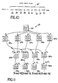
- FIG. 12 and 13 another type of meta test is used with an "at least" rule.
- the test expression of the left hand-side 26 ⁇ of rule 5 is satisfied if test T1 and at least two of tests T2-T5 are passed.
- the expression "at least 2 of" in left-hand side 26 ⁇ is a test connector 25 that is not easily represented by a RETE-net.
- One RETE-net representation 130 for left-hand side 26 ⁇ is shown in Fig. 13 and requires nine join nodes 136a-136i to combine the tokens t1-t5 produced by test nodes 134a-134e.
- RETE-net 130 produces six complex tokens (t3-t2-t1, t4-t2-t1, t5-t2-t1, t4-t3-t1, t5-t3-t1, t5-t4-t1), the presence of any one of which indicates that the left-hand side 26 ⁇ of rule 5 is satisfied.
- Fig. 15 shows the RETE-net representation 140 for left hand side 26′′′.
- Test nodes 144a-144e feed ten AND join nodes 146a-146j and twenty-eight NOT join nodes 148a-148bb to produce eleven output tokens representing the eleven possible instances of left-hand side 26′′′.
- RETE-net 36 represents meta tests (such as the test expressions in the left-hand sides of rules 4-6) is modified by creating new nodes which allow the occurrences of one or more conditions being tested by regular test nodes or join nodes in the RETE-net to be counted.
- the left-hand side of "OR" rule 4 (Fig. 10), "at least” rule 5 (Fig. 12), and “at most” rule 6 (Fig. 14) can each be represented by a simple RETE-net 150 which includes new nodes in addition to the regular start node 152, test nodes 154a-154d, and join nodes 156a-156d.
- the new nodes are RELAY nodes 158a-158d and COUNTER node 160, which cause tokens to be applied by processor/controller 46 to a shared token memory table 200.
- Processor/controller 46 performs tests on the tokens stored in memory table 200 according to the meta test function 210.
- RELAY nodes 158a-158d and COUNTER node 160 are created by compiler 32 (Fig. 1) when expert system program 12 is compiled into inference engine 34.
- Processor/controller 46 sends token t1 from test node 154a to the left memories 52 (Fig. 3) of join nodes 156a-156d, and also passes token t1 to COUNTER node 160 for use as an index for storage of complex tokens (from RELAY nodes 158a-158d via respective join nodes 156a-156d) in rows of shared memory table 200.
- the right memories 54 of join nodes 156a-156d receive tokens t2-t5 from test nodes 154b-154e, respectively.
- Processor/controller 46 produces complex tokens for memory table 200 by matching tokens in the left and right memories 52, 54 of join nodes 156a-156d in the same manner as described above.
- Each RELAY node e.g., node 158a
- Each RELAY node identifies a columns in shared memory table 200, and enables processor/ controller 46 to send the complex tokens (e.g , token t2-t1) from join nodes 156aq-156d to the assigned columns in table 200.
- the data structure 170 of RELAY nodes 158a-158d includes a field 172 that holds a pointer containing the address (191, Fig. 19) of counter node information 190 which is shared by RELAY nodes 158a-158d and COUNTER node 160.
- Field 173 holds a pointer that identifies the column in shared memory 200 to which tokens are sent from the RELAY node 158a-158d.
- the data structure 180 of COUNTER node 160 includes field 182 that contains the address 191 of the shared counter node information 100 (Fig. 19).
- the data structure 190 of the counter node information that is shared by RELAY nodes 158a-158d and COUNTER node 160 includes a field 192 that contains a pointer that identifies the location in memory 33 (Fig. 1) of the meta-test function of COUNTER node 160 (e.g., the "OR”, "at least", or the "at most” expressions of rules 4-6).
- Field 193 contains the arguments (e.g., 1, 2, etc.) of the meta-test function. That is, for rule 5 (Fig.
- test pointer in field 192 indicates the location in the memory 33 of inference engine 34 where an "at least" test sequence resides, and the arqument in field 193 provides the number (i.e., 2) of tests T2-T5 which must pass along with T1 for the left hand side of the rule to be satisfied.
- Field 194 contains a pointer to the starting address of the shared token memory table 200 of complex tokens t2-t1, t3-t1, t4-t1, t5-t1 from RELAY nodes 158a-158d, respectively.
- Shared token memory table 200 is indexed by tokens t1 from COUNTER node 160 in a manner discussed in detail below.
- Field 195 holds a pointer to a list of pointers that contain the addresses of the left memories 52 of successor nodes (not shown) in the RETE-net 36 for all of the rules in system 10.
- RETE-net 150 is shown in Fig. 16 as having terminal node 162 as its only successor node.
- the address 91 of terminal node 162 (Fig. 7) is included in the list of pointers associated with field 195.
- shared token memory table 200 includes columnss 202a-202d for complex tokens from join nodes 156a-156d, respectively, and identified in fields 173 of RELAY nodes 158a-158d, respectively.
- complex tokens t2-t1 representing instances of tests T2 and T1 passing in the combination (e.g., AND) represented by join node 156a are assigned to column 202a.
- Instances of tests T3 and T1 passing according to the function of join node 156b are represented by complex tokens t3-t1 assigned to column 202b.
- Column 202c is designated for complex tokens t4-t1, which represent instances of tests T4 and T1 passing in the combination tested by join node 156c.
- Complex tokens t5-t1 representing instances of tests T5 and T1 passing according to the function of join node 156d, are assigned to column 202d.
- columns 202a-202d are indexed into rows 204a-204n according to tokens t1 passed to COUNTER node 160 by test node 154a.
- Each row 204a-204n is associated with a token t1 that identifies a data element (by the pointer in field 102, Fig 8).
- Only complex tokens from join nodes 156a-156d and RELAY nodes 158a-158d that can be traced (via the lists of pointers associated with their data structure fields 112, Fig. 9) to that data element are eligible to be placed in that row 204a-204n.
- processor/controller 46 stores the data element in working memory 54, creates a primitive add token t(A) that points the storage location of data element A (Fig. 8), and applies the new token t(A) to start node 152 (220).
- Processor/controller 46 then sends token t(A) from start node 152 sequentially to test nodes 154a-154e. Assume that data element A passes test T1 (222). Processor/controller 46 sends this add token t1(A) from test node 154a to COUNTER node 160 (224). COUNTER node 160 creates row 204a in memory table 200 that is dedicated to complex tokens from join nodes 156a-156d (via RELAY nodes 158a-158d, respectively) that are associated with a t1 token that points to data element A (226). Token t1(A) is also stored in the left memories (LM) 52 of join nodes 156a-156d by processor/controller 46 (228).
- LM left memories
- COUNTER node 160 calls meta test function 210 each time that a new row (e.g., row 204a) is established in table 200. This is because some rules (e.g., "at most” rule 6) are satisfied as soon as test T1 is passed. If the rule is satisfied, processor/controller 46 marks the newly-created row “T” or true; otherwise, the row is marked "F” or false.
- a new row e.g., row 204a
- processor/controller 46 marks the newly-created row "T” or true; otherwise, the row is marked "F” or false.
- processor/controller 46 sequentially performs the tests identified by test nodes 154b-154e on data element A (230). The testing process continues until tests T2-T5 have all been run (232). Assume that data element A does not pass any of tests T2-T5. Then, no join node 156a-156d will have a match between tokens in its left and right memories 52, 54 (234) because the right memories 54 of join nodes 156a-156d are all empty.
- processor/controller 46 can proceed no further with data element A, and checks whether any more new data elements 56 are available (238). This would also be done if data element A failed all tests T1-T5. If there are more available data elements 56, the process continues (220) for the next data element (e.g., data element B).
- processor/controller 46 finds a match (234) at join node 156c between primitive add tokens t1(A), t4(B) in left and right memories 52, 54.
- processor/controller 46 generates a complex add token (Fig. 9) containing a pointer to a list of pointers 112 containing the addresses 101 (Fig. 8) of primitive tokens t4(B) and t1(A), and sends the complex token t4(B)-t1(A) to RELAY node 158c (242).
- Complex token t4(B)-t1(A) indicates that tests T4 and T1 have been passed. Because RELAY node 158c has access to shared counter node information data structure 190 (via the pointer in field 172), processor/controller 46 determines that complex token t4(B)-t1(A) is to be placed in row 204a of memory table 200 (i.e., the row that is assigned to primitive token t1(A)), and thus stores complex token t4(B)-t1(A) in row 204a of column 202c (i.e., the column assigned to RELAY node 158c, as identified by the pointer in field 173, Fig. 17) (244).
- Memory row test function 210 is then called by RELAY node 158c to cause processor/controller 46 to perform the meta-test associated with test pointer 192 and test arqument 193 on row 204a (because it is the only row to which a token has been just added) to determine whether the number of complex add tokens in columns 202a-202d of row 204a satisfy the meta-test (246).
- rule 5 (Fig. 12) is being represented by RETE-net 150.
- processor/controller 46 checks whether at least two of tests T2-T5 are passed along with a given instance of test T1 being passed by determining whether there are at least 2 columns 202a-202d in row 204a that contain complex add tokens (246).
- token t4(B)-t1(A) Because only one complex add token, token t4(B)-t1(A), is presently in row 204a, the left-hand side of rule 5 is not yet satisfied, and processor/controller 46 maintains row 204a marked "F” or false (Fig. 20).
- processor/controller 46 sends these complex tokens to RELAY node 158c (242), places in the proper column and row of memory 200 (244) and performs test function 210 on that row (246).
- processor/controller 46 repeats the inference process for the next data element, if any (238).
- Processor/controller 46 sends add token t1(C) from test node 154a to COUNTER node 160, which creates row 204b in memory table 200 for the primitive token and data element C (226). Primitive token t1(C) is also stored in the left memories of join nodes 156a-156d (228). A new token match occurs (234) in join node 156c, and processor/controller 46 sends a new complex add token t4(B)-t1(C) to RELAY node 158c (242).
- complex token t4(B)-t1(C) is sent from RELAY node 158c to in row 204b, columns 202c of memory table 200 (244). This row 204b does not yet satisfy the "at least 2" test of test function 210 (246), however, and row 204b is maintained marked “F” or false. The inference process is then repeated for a new data element 56, if any (238).
- Processor/controller 46 sends add token t2(D) from test node 154b to the right memories 54 of join nodes 156a-156d (240). A match is thus made between token t2(D) and token t1(A), and a complex add token t2(D)-t1(A) is sent by processor/controller 46 to RELAY node 158a (242).
- processor/ controller 46 sends the complex add token from RELAY node 158a to row 204a of column 202a in memory table 200 (244). Now, test function 210 is satisfied (246), because there are complex add tokens in at least two columns of row 204a. That is, data elements A, B, and D have resulted in an instance of the left-hand side of rule 5 being satisfied.
- ROW 204a is changed from "F” to "T” or true, and processor/controller 46 generates a new complex token (Fig. 9) which contains, in field 112, a pointer to the address 181 of COUNTER node 160 (Fig.
- processor/controller 46 sends complex add token t2(D)-t1(C) to RELAY node 158a (242), and stores the token in columns 202a of memory table 200 at the row 204b associated with t1(C) (244).
- Complex add tokens are now present in at least two columnss of row 204b (246), and thus another instance of the left hand side of rule 5 is satisfied and must be dealt with.
- Processor/controller 46 changes the tru/false condition of row 204b from “F” to "T” or true and generates a new complex token t c -t1(C) (250) which is stored in terminal node 162 (252).
- processor/controller 46 determines (based on test function 210) that a row (e.g., row 204a) has passed due to the addition of an add token to a columns of that row, it checks whether the true/false (T/F) condition of that row is changed (249). If not (i.e., if the row had previously satisfied test function 210), processor/controller 46 does not generate a new complex add token (representing a new rule instance), and the process proceeds to step 248.
- T/F true/false
- a complex delete token is sent by processor/controller 46 via a RELAY node 158a-158d to remove a corresponding complex add token from a column of a row of memory table 200, and if as a result the T/F condition of that row changes (249) from true to false (i.e., test function 210 is no longer satisfied for that row, processor/controller 46 generates a complex delete token (250).
- the complex delete token also points to the address 181 of COUNTER node 160 and to the address 101 of the primitive token associated with that row (e.g., primitive token t1(A) for row 204a). This complex token is sent by processor/controller 46 to terminal node 162 (252).
- processor/controller 46 After add and delete tokens for all new data elements have been applied to RETE-net 150 (238), processor/controller 46 checks terminal node 162 for the presence of complex add tokens (254). If terminal node 162 is empty, no instances of rule 5 are ready to fire and execution of expert system program 12 is complete (256), at least for all of the data that has been obtained by inference engine 34 so far.
- processor/controller 46 repeats the inference process starting at step (220) for each new data element. If no new data is generated or obtained, operation is complete (256).
- join nodes 156a-156d identify tests on data elements as a condition for matching tokens in left memories 52 with tokens in right memories 54.
- join node 156c besides identifying a logical AND function between tokens in left memory 52 and tokens in right memory 54, also identifies a test (via field 84, Fig. 6) that specifies that a data element associated with a left memory token must have a value greater than the value of a data element associated with a right memory token in order for a match to occur.
- data element A is not greater than data element B, but data element C is greater than data element B.
- processor/controller 46 would not find a match between tokens t1(A) and t4(B) at join node 156c, but a match between tokens t1(C), t4(B) would still be found.
- memory table 200 indexed by rows 204a, 204b assigned to tokens t1(A), t1(C), respectively, processor/controller 46 is able to correctly send complex token t4(B)-t1(C) (via RELAY node 158c) to row 204b instead of row 204a. This correctly indicates that an instance of the left-hand side of rule 5 being satisfied has occurred with data element C, but not with data element A.
- RETE-net 150 can represent a wide variety of meta tests by identifying the appropriate test (field 192, Fig. 19) and test arguments (field 193) of test function 210.
- test rule 4 can also be implemented with RETE-net 150.
- the test arguments (field 193, Fig. 19) are simply set to 1.
- the execution of test function 210 will cause a complex token to be sent to terminal node 162 for a given row 202a-202n of memory table 200 whenever one complex add token is stored in that row and causes the T/F condition of the row to change.
- RETE-net 150 can also represent the left-hand side of "at most 2" rule 6.
- the test pointer (field 192) and test arguments (field 193) are selected so that test function 210 is satisfied if, for a given row in memory table 200, zero, one or two complex tokens are present in columns 202a-202d. However, no token is sent to terminal node 162 for a row if three or more complex tokens are stored in that row.
- RETE-net 150 can implement many other combinations of an arbitrary number of tests, for example, determining whether greater than X but fewer than Y tests have been passed, or determining whether between X and Y tests have been passed. Still another example is checking whether an odd or even number of tests have been passed, or whether a specific combination of tests (i e., the first, third, and fourth tests) have passed.
- RETE-net 150 can also represent rule left-hand sides that do not contain an indexing test (i.e., a test, like T1 of rules 4-6, that must pass along with the meta-test of tests T2-T5).
- a test like T1 of rules 4-6, that must pass along with the meta-test of tests T2-T5
- Compiler 32 (Fig. 1) recognizes such a non-indexed meta-test and creates a special test node (154a) which applies tokens to COUNTER node 160.
- Compiler 32 establishes test nodes 154b-154e for tests T2-T5, respectively, and arranges the remainder of RETE-net 150 as shown in Fig. 16.
- Compiler 32 also creates a special data element that has only one allowed value and which is capable of passing only the special test of node 154a.
- the creation of the special test node and data element is invisible to the programmer (i.e., the author of the non-indexed meta-test rule).
- processor/controller 46 sends the token associated with the special data element to RETE-net 150, and the special data element passes the only special test of node 154a.
- the special token is matched in join nodes 156a-156d with any token from respective test nodes 154b-154e, and complex tokens that identify the special token are sent to RELAY nodes 158a-158d.
- the complex tokens from RELAY nodes 158a-158d are placed in columns 202a-202d (Fig. 20) of the row in memory table 200 that is identified by the special token from COUNTER node 160.
- Processor/controller 46 performs test function 210 on this row in the same manner as described above.
- data definitions 14 in expert system program 12 include one or more data categories (e.g., name, age, height, weight) and, for each category, an initial data value and a set of values that the data is allowed to have. For example, height is initially set to "Y" and is permitted to have a value that is less than 100.
- the data definition categories which will be subject to on-demand data gathering e.g., "age” are selected and assigned an initial value, " ⁇ unasked>". If during the execution of expert system program 12 data elements having allowed values are obtained for ⁇ unasked> data definitions, then, of course, data for these categories will not be "missing", and the initial ⁇ unasked> value will be overwritten by the allowed values that are obtained.
- compiler 32 recognizes tests that deal with ⁇ unasked> data definitions and structures these tests to perform a test for the ⁇ unasked> value if the primary function of the test fails.
- compiler 32 compiles left-hand side 270 as if it were the left hand side 270 (Fig. 24) of a rule 7′ in which test T1′, if the value of age is not equal to 7, asks whether age has the value ⁇ unasked>. If so, test T1′ passes. Because height is not an ⁇ unasked> data definition, test T2 is not changed.
- Compiler 32 also changes the action list 271 (Fig. 23) of rule 7 to an action list 271′ that, if rule 7 passes because age data is missing, causes processor/controller 46 to initiate a data gathering sequence for age in place of firing the rule, as described in detail below.
- processor/controller 46 changes the data structures 280 of both primitive and complex tokens to keep track of the number of tests associated with each token that have passed because data is missing for a data definition that has an ⁇ unasked> initial value.
- the conflict resolution fields 281 of all primitive and complex tokens are augmented with a counter 282 that keeps track of the number of tests that have passed despite data being missing for ⁇ unasked> data definitions.
- the remaining fields 283 of the primitive and complex token data structures 280 are unchanged.
- left-hand side 270′ of rule 7′ is represented by RETE-net 290, with primitive tokens t being sent from processor/controller 46 from start node 292 to a pair of test nodes 294a, 294b that identify tests T1′ and T2, respectively.
- processor/controller 46 sends primitive tokens t1, t2 respectively, to the left memory and the right memory, respectively, of join node 296.
- Processor/controller 46 checks for matches between left and right memory primitive tokens at join node 296 and sends complex tokens t2-t1 representing successful matches to terminal node 298.
- Processor/controller 46 applies each primitive token t to RETE-net 290 with its ⁇ unasked> counter 282 initialized to zero. Processor/controller 46 increments the the ⁇ unasked> count of the primitive token t at test node 294a only if the test for the ⁇ unasked> value is both performed and passed.
- the amount by which ⁇ unasked> counter 282 is incremented depends on the number of data definitions in the data element 56 represented by token t that are tested and that have ⁇ unasked> values. For example, if a data element represented by token t includes only one data definition that has an ⁇ unasked> value that is tested (and passed) at node 294a, the ⁇ unasked> counter 282 of token t is incremented by one.
- processor/controller 46 will increment the ⁇ unasked> counter 282 of the token t representing this data element by four when it sends the token to join node 296.
- the contents of ⁇ unasked> counter 282 in a complex token t2-t1 created by join node 296 is the sum of the contents of the ⁇ unasked> counters 282 of the tokens t1, t2 that are matched to form the complex token.
- processor/controller 46 places each new data element 56 that it obtains in working memory 54, and creates a token t for it (302).
- processor/controller 46 checks whether the value of the data definition "age” equals ⁇ unasked> (308). Assuming that no data has yet been obtained for age, the value of the data definition will equal ⁇ unasked>, satisfying test T1 (310). Before token t1 is sent to join node 296, processor/controller 46 increments the ⁇ unasked> counter 282 of token t1 to a count of "1" (312).
- processor/controller 46 checks whether one or more matches exist between the new token t1 in left memory (LM) 52 and any t2 tokens that currently reside in right memory (RM) (314). If so, processor/controller 46 generates a complex token or tokens t2-t1, each of which has an ⁇ unasked> count in counter 282 equal to the sum of the ⁇ unasked> counters 282 of primitive tokens t1, t2 that were matched (316). Each new complex token is then sent by processor/controller 46 to terminal node 298 (318).
- a join node represents a function other than a logical AND (e.g., a NOT function, or a test of whether the value of the data element associated with one token is, e.g., greater than that associated with another token)
- the function associated with the join node is slightly changed.
- Test functions e.g., "greater than” tests
- the NOT function is altered to ignore tokens that have non-zero ⁇ unasked> counts when applying the NOT function. This prevents a failure being inadvertently indicated by the NOT function simply because a data definition is ⁇ unasked>.
- token t is also sent to test node 294b, and test T2 (i.e., height ⁇ 60) is performed on the associated data element (320). Assume that the new data element passes T2 (but did not pass T1). Processor/controller 46 sends token t2 to the right memory (RM) of join node 296 (322). Had test T2 not passed, the next step would be to apply the next data element, if any (336), to RETE-net 290, because height is not ⁇ unasked> (324). (But if height was ⁇ unasked>, the test would pass (326) and the ⁇ unasked> count of token t2 would be incremented (328) from zero.)
- Processor/controller 46 performs a logical AND function (according to left hand side 271′ of rule 7′) to check for a match between the new t2 token and any t1 token that currently resides in the left memory (LM) of join node 296 (330). In this example, a match will be found, and processor/ controller 46 generates a complex token t2-t1 that has a value of "1" in its ⁇ unasked> counter 282, because token t1 was sent (306) to join node 296 as the result of age being ⁇ unasked> (332). The new complex token t2-t1 is stored by processor/controller 46 in terminal node 298 (334).
- processor/controller 46 checks all of the terminal nodes in the RETE-net (e.g., node 298) for the presence of complex tokens (338). If none are found, no rule left-hand side is satisfied, and the process terminates (340).
- processor/controller 46 performs conflict resolution between the complex tokens to obtain a single complex token with which to proceed (344). However, no conflict resolution is needed if only one complex token is found in the terminal nodes.
- conflict resolution is performed on the complex tokens in an order of preference determined by the ⁇ unasked> count 282 of the complex tokens.
- Tokens having an ⁇ unasked> count of 0 have priority (344a) over tokens with an ⁇ unasked> count of 1, which in turn have priority (344b) over tokens having an ⁇ unasked> count of 2 (344c).
- the lowest priority complex tokens are those with the maximum possible ⁇ unasked> count (i e., N) (344n), which is related to the highest number of tests contained in the left-hand side of any rule.
- processor/controller 46 fires the instance of the rule whose left-hand side is associated with the terminal node that contains that complex token (348). This is because that complex token represents an instance in which the left-hand side of that rule is satisfied by actual values of data elements 56 stored in working memory 54. That is, none of the tests in the left-hand side of the rule has passed as the result of data being missing for one or more ⁇ unasked> data definitions. If any new data is generated from the firing of the rule (350), that data is obtained and applied to RETE-net 290 in the same manner as described above. Otherwise, the procedure terminates (340).
- the rule associated with the complex token is not fired, because data values of one or more data elements associated with the token are missing.
- the rule is not ready to be fired, because one or more pieces of data are missing.
- processor/controller 46 identifies the ⁇ unasked> data definition or data definitions for which data is missing by following the pointers in field 112 of the complex token back to the addresses 101 of the primitive tokens from which the complex token is formed.
- the first primitive token in this list that has an ⁇ unasked> counter that contains a value of 1 is selected.
- the pointer in field 102 (Fig. 8) of that primitive token is traced to the working memory location of its data element (which has the value ⁇ unasked>), from which an ⁇ unasked> data definition that was tested to produce this primitive token is identified (352).
- a data element can contain more than one data definition, more than one of which can have a value of ⁇ unasked>, the first data definition in the data element that has an ⁇ unasked> value is identified. If the data element itself is set to a value of ⁇ unasked>, the first data definition in the data element is identified.
- missing data for this definition can be obtained (354) in a number of ways. For example, processor/controller 46 can simply identify the data definition to the user and wait for the user to enter the missing data. Alternatively, processor/controller 46 may run one of the other programs 18 (Fig. 1) to calculate the missing data.
- processor/ controller 46 loads it into working memory 54 as one or more data elements 56, for which new primitive add tokens are created (302).
- a delete token for the previous value ⁇ unasked> of the data definition is applied to RETE-net 190, followed by the add tokens which represent the obtained data values.
- memory table 200 can alternatively be indexed (via COUNTER node 160) by complex tokens rather than by primitive tokens.
Abstract
Description
- This invention relates to rule-based artificial intelligence systems (i.e., so-called "expert systems") in which the various conditions defined by the rules are structured as a discrimination net to allow efficient determination of which rules are applicable to data obtained by the system.
- An expert system is based on a computer program which comprises a set of rules and defines types of data that will be processed according to the rules. By a process known as "inference", the system performs matching between rules and data in a working data base that is obtained by the system from a user or from other data bases to determine which rules apply, and one or more of these rules is "fired" (i.e., applied to the data) to change the data in the working data base, provide advice to the user or explanations in response to the user's questions, or to take some other action. The inference process is repeated until no rules are found to be applicable to the data, or the firing of rules no longer produces a result.
- Each rule includes one or more conditions (collectively referred to as the "left-hand side" of the rule) which, if satisfied by the data, indicate that the rule is applicable. The operations to be performed when the rule is fired are listed in the "right-hand side" of the rule. One way to determine which rules are applicable is to test every condition in the left hand sides of all of the rules each time a new element of data is obtained by the system. With this scheme, conditions that are found satisfied (or not satisfied) by data in the working data base are retested each time the working data base is altered by addition or deletion of data, even if the altered data could not possibly have changed the result of the test. Also, often the same condition is found in the left-hand side of more than one rule, and thus is tested multiple times whenever a new data element is obtained.
- To avoid this, some expert systems structure the left-hand sides of the rules as a "discrimination net", such as a so-called "reticular" net or RETE-net. A RETE-net more efficiently determines which rules are applicable by testing, when the working data base is changed, only those conditions having results that may have changed in response to the changed data in the working data base. Also, RETE-nets cause conditions that are common to more than one rule to be tested only once each time the working data base changes.
- A RETE-net is a data structure in which the conditions of all rules are arranged as a network of nodes. The conditions of the rules are identified by test nodes that are interconnected by a set of join nodes to represent the various combinations of conditions that are specified in the left-hand sides of the rules. A condition is represented by a single test node, even if that condition occurs in the left-hand sides of multiple rules. Tokens that represent data in the working data base are passed via the nodes through the RETE-net as the data pass various tests and combinations of tests. The RETE-net terminates at result nodes that each correspond to an individual rule. If the left-hand side of a rule is satisfied, the RETE-net stores a token in the result node corresponding to that rule.
- RETE-nets work well when the combinations of conditions in the left-hand side of a rule are of the kind that can easily be represented as such a network of nodes. For example, a rule left-hand side that requires
condition 1 ANDcondition 2 ANDcondition 3 ANDcondition 4 to be satisfied is represented with an AND node joining the test nodes forconditions condition 3 test node, and a third AND node joining the second AND node and the test node forcondition 4. - It is often desirable that the left-hand side specify a more flexible combination of conditions, for example:
condition 1 AND (at least 2 of:conditions condition 1 test node with permutations of the test nodes forconditions - It is possible that during an inference cycle the conditions of no rule will be satisfied, but one or more conditions are unsatisfied, not because data is incorrect but because data that would satisfy the condition is missing from the data base. The missing data must be identified and supplied in order to continue.
- RETE-net-based expert system programs typically attempt to identify the missing data with special rules that cause the inference process to proceed in the reverse direction (i.e., "backward chaining"), or by asking the user a limited series of questions. In addition, the expert system program may be augmented with special rules (called "null condition" rules) that have conditions which are always satisfied and that are fired only if the left-hand side of no other rule is satisfied. The "actions" taken by null condition rules are selected to help the user recognize that data is needed and to provide a guide for identifying the missing data
- In one aspect of the invention, an expression comprising conditions is evaluated based on values of data elements presented to a network of a kind in which the conditions are represented by nodes and the relationships among conditions in the expression are represented by links among the nodes, by storing information that identifies which conditions represented by at least some of the nodes have been satisfied by the values of the data elements, and testing the stored information in accordance with the expression as a basis for evaluating said expression.
- Preferred embodiments include the following features.
- The information is stored in separate locations assigned to information from different nodes, and the information from each node is entered into the location assigned to that node. The expression is satisfied if a predetermined number of the conditions in the expression have been satisfied, and the number of locations that are occupied with information are counted to determine how many conditions have been satisfied.
- In one embodiment, the expression includes an indexing condition represented by a node, and groups of the locations are established in storage based on information from the indexing condition node, with each group being associated with the data elements that satisfy the indexing condition. The information from the nodes identifies the data elements that satisfy the indexing condition and is entered in the locations of the group that corresponds to the identified data elements. The number of locations in each group that are occupied with information from the nodes are counted to determine whether the expression is satisfied.
- Each group is monitored to determine whether the group currently has a count of occupied locations that indicates that the expression is satisfied. Occupied locations in a group are counted each time a new entry of information is made in that group.
- The expression is indicated to be satisfied if a new entry of information causes a group that did not previously have a count of occupied locations that indicated satisfaction of the expression to have a count of occupied locations that indicates that the expression is satisfied. But the indication is not made if the group already had a count of occupied locations that satisfied the expression at the time that the new entry is made into the group
- Some nodes are adapted to cause the information to be deleted from corresponding occupied locations in storage, and the occupied locations in a group are counted each time that information is deleted from a location in that group. An indication is made that the expression is not satisfied if a deletion of information causes a group that previously had a count of occupied locations that satisfied the expression to have a count of occupied locations that does not satisfy the expression.
- As a result, the network, which is preferably a discrimination net, such as a reticular net (i.e., a RETE-net), efficiently represent expressions, such a meta-tests, that are satisfied by a combination of some, but less than all, of the conditions in the expressions. Specific examples of these meta tests include expressions that are satisfied if any one of the conditions are satisfied, or if at least (or at most) a predetermined number of the conditions are satisfied. The network enables results of the evaluation to be available at a single location (e.g., in a terminal node in the RETE-net), thereby facilitating a determination of whether the expression is satisfied.
- In a second aspect, the invention features evaluating an expression that comprises conditions which pertain to possible values of data belonging to categories of data based on actual values of data presented to a network of a kind in which the conditions are represented by nodes, by identifying a category of data for which values need not occur in the network in order for a condition that requires a value in the category to be provisionally satisfied, and causing the node that represents the condition to indicate that the condition is provisionally satisfied even when no values in the identified category occur in the network.
- Preferred embodiments include the following features.
- The category is identified by assigning to it a predetermined value, which is maintained until a value belonging to that category has occurred in the network. Each node having a condition that tests for a value in the identified category tests, if the condition is not satisfied, whether the category has the predetermined value and, if so, the node indicates that the condition is provisionally satisfied.
- The expression is deemed to have been satisfied if a predetermined combination of nodes indicate that the conditions represented by the nodes are satisfied or are provisionally satisfied, and, if the expression is satisfied, the number of conditions that are indicated to be provisionally satisfied are identified. The expression is associated with a rule, and the rule is fired if the number of conditions that are indicated to be provisionally satisfied is zero.
- Preferably, there are a plurality of expressions, each of which is satisfied if a predetermined combination of nodes indicate that the conditions in that expression are satisfied or are provisionally satisfied; for each expression that is satisfied, the number of conditions that are indicated to be provisionally satisfied is identified. Priority is determined between satisfied expressions based on the number of conditions that are indicated to be provisionally satisfied for each. The expressions are each associated with a rule, and one rule is selected based on the priority determination.
- The selected rule is fired if the number of conditions that are indicated to be provisionally satisfied for the satisfied expression that is associated with the selected rule equals zero. On the other hand, if the number of conditions that are indicated to be provisionally satisfied is more than zero, the identified category of data for which no values occur in the network is selected, and a value for the selected category of data is obtained.
- As a result, categories for which data are missing are efficiently identified by a mechanism that is invisible to the user. No special rules, null condition rules, or backward chaining is required. Thus, the missing data can easily be retrieved, either by the user or by running a separate program.
- Other features and advantages of the invention will be apparent from the following detailed description, and from the claims.
- We first briefly describe the drawings.
- Fig. 1 is a functional block diagram of an expert system.
- Fig. 2 is a diagram representative of rules used in the system of Fig. 1.
- Fig. 3 is a diagram of a reticular net (i.e., a RETE-net) representation of the rules of Fig. 2.
- Fig. 4 is a data structure of one type of node in the RETE-net.
- Fig. 5 is a data structure of a second type of node in the RETE-net.
- Fig. 6 is the data structure of a third type of node in the RETE-net.
- Fig. 7 is a data structure of a fourth type of node in the RETE-net.
- Fig. 8 is the data structure of a primitive token used in the RETE-net.
- Fig. 9 is the data structure of a complex token used in the RETE-net.
- Fig. 10 is a diagram of an "OR" rule.
- Fig. 11 is a diagram of a conventional RETE-net for the "OR" rule of Fig 10.
- Fig. 12 is a diagram of an "at least" rule.
- Fig. 13 is a diagram of a conventional RETE-net for the "at least" of rule of Fig. 12.
- Fig. 14 is a diagram of an "at most" rule.
- Fig. 15 is a diagram of a conventional RETE-net for the "at most" rule of Fig. 14.
- Fig. 16 is a RETE-net for the rules of Figs, 10, 12, and 14 according to one aspect of the invention.
- Fig. 17 is the data structure of one of the nodes in the RETE-net of Fig. 16.
- Fig. 18 is the data structure of another one of the nodes in the RETE-net of Fig. 16.
- Fig. 19 is a data structure of information that is shared by the nodes of Figs. 17 and 18.
- Fig. 20 is a diagram useful in understanding the operation of the RETE-net of Fig. 16.
- Fig. 21 is a flow chart illustrating the operation of the RETE-net of Fig. 16.
- Fig. 22 is a diagram of data definitions.
- Fig. 23 is a diagram of a representative rule.
- Fig. 24 is a diagram of the rule of Fig. 23 modified according to a second aspect of the invention.
- Fig. 25 is a diagram of the data structures of primitive and complex tokens, modified according to the second aspect of the invention
- Fig. 26 is a diagram of a RETE-net for the rule of Figs. 23 and 24.
- Figs. 27 and 28 are flow charts useful in understanding the operation of the second aspect of the invention.
- Referring to Fig. 1,
expert system 10 executes anexpert system program 12 created using any suitable expert system programming language (such as OPS5, available from Digital Equipment Corporation).Expert system program 12 includes a set ofdata definitions 14 that identify categories of data whichprogram 12 will use during operation. For example, ifprogram 12 is to be used with data concerning people,data definitions 14 might include categories such as name, age, sex, height, and weight.Program 12 also includes a set of rules, described byrule definitions 16, for manipulating actual data that fitdefinitions 14 and that are obtained bysystem 10.Expert system program 12 also includes links toprograms 18 in other languages (such as C, Fortran, Basic, etc.) for performing tasks (e.g., accessing remote databases, making statistical computations) when called upon during the execution ofexpert system program 12. - Referring to Fig. 2, a set of rules 20 (e.g., rules 1-3) described by
rule definitions 16 each includes one or more conditions or tests 22 (e.g., tests T1-T4) that are joined by test connectors 24 (e.g., "ANDs") to form an expression known as theleft hand side 26 of the rule. Arule 20 is applicable to the data obtained bysystem 10 only if the data satisfies the expression oftests left hand side 26 of that rule. For example,rule 1 is applicable only if the data passes tests T1, T2, and T3 (i e., only if tests T1-T3 are all "true"). Test T2 is also in the left-hand side 26 ofrule 2 and must be true along with test T4 forrule 2 to be applicable. Similarly, tests T1, T3, and T4 all must be true for left-hand side 26 ofrule 3 to be satisfied - The right hand side 28 of each
rule 20 contains an "action list" 30 that is executed if the rule is fired. For example, the firing of a rule might causesystem 10 to obtain more data or compute the value of some data (for example, by executing one of other programs 18). A rule firing may also cause some external action to be taken (such as displaying data or changing an external database 48). - Referring again to Fig. 1,
data definitions 14 andrule definitions 16 are compiled by acompiler 32 in a manner described in detail below and stored in amemory 33 of aninference engine 34 as a type of discrimination net data structure known as a reticular net 36 (i.e., a RETE-net). (Theother programs 18 are compiled by theirown compilers 33 and applied to processor andcontroller 46 ininference engine 34.) - Referring also to Fig. 3, in RETE-net 36 the distinctions between the left-hand sides of individual rules 20 (Fig. 2) are eliminated, and the individual tests T1-T4 are each represented by a
single test node 40a-40d, respectively, regardless of how many rules thetests 22 appear in. For example, test T1 is represented by asingle test node 40a, even though test T1 appears in the left-hand sides 26 of bothrules -
Test nodes 40a-40d are fed by acommon start node 38 in a manner described in detail below. The outputs oftest nodes 40a-40d are interconnected through a set of join nodes 42a-42e to a set of result or terminal nodes 44a-44c. Join nodes 42a-42e represent the function (in this case, "ANDs") of thetest connectors 24 in the left-hand sides 26 of rules 20 (Fig. 2). - Each terminal node 44a-44c is associated with the left-
hand side 26 of one ofrules 20. Thus, the path fromstart node 38 throughtest nodes 40a-40d and join nodes 42a-42e to each terminal node 44a-44c represents the test expression in the left-hand side 26 of one ofrules 20. For example, the outputs oftest nodes test node 40c in AND joinnode 42b. The result, applied to terminal node 44a, represents the test expression [(T1) AND (T2) AND (T3)] which comprises the left-hand side 26 ofrule 1. - Similarly, the outputs of
test nodes node 42c and the result applied toterminal node 44b as a representation of the expression [(T2) AND (T4)] specified in the left-hand side 26 ofrule 2. Finally, the expression in the left-hand side ofrule 3, namely [(T1) AND (T3) AND (T4)], is represented in RETE-net 36 by the interconnection of the outputs oftest nodes node 42d, the output of which is joined with theoutput oftest node 40d in AND joinnode 42e and applied to terminal node 44c. - Additionally, each terminal node 44a-44c identifies the
action list 30 of the rule with which the terminal node is associated. For example, terminal node 44a identifies theaction list 30 ofrule 1. - A processor/
controller 46 ininference engine 34 obtains working data in a variety of ways, for example, fromdata base 48 or the user via auser interface 50, by performing initial computations specified bydata definitions 14, or by executing right hand sides 28 of rules 20 (Fig 2). Processor/controller 46 stores this data in a workingmemory 54 as a set ofdata elements 56. Adata element 56 identifies one or more data definitions and a value for each definition. For example, adata element 56 could comprise one category (e.g., age) and an associated value, or a number of categories (e.g., name, age, height, sex, and weight) and a data value for each category. - In operation, whenever
new data elements 56 are stored in workingmemory 54, processor/controller 46 creates "add" tokens for them and applies the tokens one at a time to RETE-net 36, which processes the tokens to determine if one ormore rules 20 are applicable to the data stored in workingmemory 54. This process is known as "matching" and is described in detail below. Ifmultiple rules 20 are applicable, or if a single rule is applicable to more than one combination of data elements, processor/controller 46 performs conflict resolution to select one or more of such rule "instances", and fires those rule instances. - The firing of a rule instance may cause several results. For example, it may create new data or cause processor/
controller 46 to calculate a new value for existing data or to obtain more data, either fromdata base 48 or from the user viainterface 50. Processor/controller 46 stores any newly acquired data aselements 56 in workingmemory 54, creates add tokens for these new data elements, and applies the new add tokens to RETE-net 36 in another inference cycle to find a rule instance for firing. Similarly, if a data value is changed during operation, processor/controller 46 applies a "delete" token representing the old data value to RETE-net 36, and then applies an "add" token for the new data value. This process continues until no applicable rules are identified or until nonew data elements 56 are generated or obtained as the result of firing the rules. - During operation, processor/
controller 46, viainterface 50, can provide advice to the user or explanations to questions from the user. Processor/controller 46 can also take other actions, such as executing one or more ofprograms 18 or displaying data to the user - In Fig. 3, processor/
controller 46 applies add or delete tokens t representing data elements 56 (called primitive tokens) to startnode 38, and then in turn to testnodes 40a-40d. Processor/controller 46 performs the test identified by eachtest node 40a-40d on the data associated with the primitive token t and, if the test passes, processor/controller 46 sends the primitive token to the appropriate join node or nodes 42a-42e. The primitive tokens that are sent fromtest nodes 40a-40d are designated t₁₋t₄, respectively, in Fig. 3, although they are identical to the token t. - Each join node 42a-42e (e.g., AND join node 42a, shown in detail in Fig. 3) includes a pair of memories, one each for the nodes from which the join node receives tokens. Thus, join node 42a includes left
memory 52 for receiving and storing tokens t₁ fromtest node 40a, and aright memory 54 to receive and store tokens t₂ fromtest node 40b. - Processor/
controller 46 attempts to match tokens in the left andright memories test connectors 26 in the rules (Fig. 2). For example, join nodes can specify a simple logical ANDing of tokens inleft memory 52 with tokens inright memory 54. (This is in fact the function of join nodes 42a-42e.) Alternatively, a join node (called a NOT join node) can specify a check for the absence of tokens inright memory 54 in conjunction with the presence of tokens inleft memory 52. Join nodes can also identify tests on the data elements associated with the input tokens to allow processor/controller 46 to determine, for example, whether a data element associated with one token is equal to, not equal to, less than, greater than, less than or equal to, or greater than or equal to the data element associated with the other token. The programmer can also specify other tests to be performed by processor/controller 46on the data elements at the join nodes. - In any of these types of join nodes, when a token match is found, processor/
controller 46 generates a new token, called a complex token, which identifies which tokens (and hence which data elements) were matched at the join node. Processor/controller 46 sends the complex token to the next node in RETE-net 36. Like primitive tokens, complex tokens can be add tokens or delete tokens. Consider, for example, applying add token t associated with data element A to RETE-net 36 at a time when one add token t₂ (associated with data element B that has passed test T2) already resides inright memory 54 of AND join node 42a. If data element A passes test T1, processor/controller 46 sends the token (labelled t₁ in Fig. 3) fromnode 40a to leftmemory 52 of AND join node 42a. Because add tokens are present in left andright memories controller 46 generates a complex add token t₂-t₁, and sends the complex token from node 42a to theleft memory 52 ofjoin node 42b. - Complex token t₂-t₁ identifies both primitive tokens t₁ and t₂ and thus also identifies data elements A, B that have passed test T1 and T2 and have satisfied the function of join node 42a.
- Continuing, suppose data element C subsequently obtained by
inference engine 34 satisfies test T3. Processor/controller 46 sends an add token t₃ which represents data element C fromtest node 40c toright memory 54 of ANT joinnode 42b. A match thus exists between primitive token t₃ and the t₂-t₁ complex token already stored inleft memory 52 ofnode 42b. Processor/controller 46 produces another complex add token, t₃-t₂-t₁, identifying primitive tokens t₃, t₂, t₁, (and thus data elements C, B, and A, respectively). - Complex add token t₃-t₂-t₁ is stored by processor/
controller 46 in terminal node 44a and indicates that the left-hand side 26 ofrule 1 is satisfied. Similarly, whenever the processing of anew data element 56 causes the left-hand side 26 ofrule 2 to be satisfied, processor/controller 46 stores a complex add token t₄-t₂ interminal node 44b from join node 46c. Also, when tests T1, T3, and T4 in the left-hand side ofrule 3 are satisfied, complex add token t₄-t₃-t₁ is stored in terminal node 44c fromjoin node 42e by processor/controller 46. - After tokens representing all of the
data elements 56 have been applied to RETE-net 36, processor/controller 46 checks terminal nodes 44a-44c to determine which rule left-hand sides 26 are satisfied, and which data elements satisfy the left-hand side or sides. It is possible that the left-hand sides 26 of multiple rules 20 (e.g., rules 1 and 2) are satisfied. It is also possible that the left-hand side 26 of a single rule (e.g , rule 1) is satisfied by more than one combination ofdata elements 56. For example, if test T3 is also satisfied by data element D, a pair of complex t₃-t₂-t₁ add tokens identifying data elements D, B, and A and data elements C, B, and A, respectively, will be present atterminal node 44a. - Each combination of
data elements 56 that satisfies a rule left-hand side 26 identifies an "instance" of therule 1, that is, defines a set ofdata elements 56 for which a rule is applicable.Inference engine 34 performs conflict resolution between multiple instances of rules to determine which one or more instances of which rule or rules to fire. When an instance of a rule (e.g., rule 1) is fired, processor/controller 46 marks as deleted the complex add token in the terminal node (e.g., token t₃-t₂-t₁ (for data elements C, B, A) in node 44a) associated with that instance, so that this rule is not considered satisfied again until another complex token is stored in node 44a (or unless more than one complex token was stored in node 44a whenrule 1 was fired). - Referring to Figs. 4-7, start
node 38,test nodes 40a-40d, join nodes 42a-42e, and terminal nodes 44a-44c are defined bydata structures inference engine 34. Thedata structure 60 ofstart node 38 is shown in Fig. 4 and includes afield 62 which holds a pointer to a list of pointers which contain the addresses of successor nodes in RETE-net 36, that is, the addresses 71 (Fig. 5) oftest nodes 40a-40d. - Referring to Fig. 5, the
data structure 70 of test noted 40a-40d includesfield 72 which is a pointer that contains the memory address of the test assigned to the test node (i e., test T1 fornode 40a).Field 73 contains a pointer to a list of pointers that hold the addresses of the left memories 52 (Fig. 3) of the node or nodes to which tokens are sent from thetest node 40a-40d. For example,field 73 fortest node 40b holds a pointer to a list containing a pointer that holds the address of left memory (LM) 52 ofjoin node 42c.Field 74 holds a pointer to a list of pointers that contain the addresses of theright memories 54 of the successor node or nodes to which tokens are sent. For example,field 74 fortest node 40b holds a list that comprises a pointer to a list that comprises a pointer that contains the address of right memory (RM) 54 of join node 42a. - Referring to Fig. 6, the
data structure 80 of join nodes 42a-42e includes afield 82 that contains a pointer to the address of the left memory (LM) 52 of the join node, and a pointer to the right memory (RM) 54 address of the node is held infield 83. A pointer infield 84 designates the location in thememory 33 ofinference engine 34 of the test (e.g., equal to, not equal to, less than, greater than, less than or equal to, greater than or equal to, or don't care) and logical function (e.g., AND or NOT) identified by the node to match left memory and right memory tokens. Unlike tokens fromtest nodes 40a-40d, tokens are passed from join nodes 42a-42e only to leftmemories 52 of successor nodes.Field 85 contains a pointer to a list of pointers that contain these left memory addresses. For example,field 85 in thedata structure 80 of join node 42a contains a pointer to the address of theleft memory 52 ofjoin node 42b . - Referring to Fig. 7, the
data structure 90 for terminal nodes 44a-44c includes afield 92 that contains a pointer to a list of pointers that contain the locations in thememory 33 ofinference engine 34 where one or more complex tokens received from the join nodes are stored. For example,field 92 for node 44a contains a pointer to a location in memory where complex tokens t₃-t₂-t₁ fromjoin node 42b are stored. The addresses 91 of terminal nodes 44a-44c are identified by pointers infields 85 of thedata structures 80 ofjoin nodes Field 93 contains a pointer to the location ininference engine memory 33 in which theaction list 30 of the rule identified by the terminal node 44a-44c is stored. - Referring to Fig. 8, the
data structure 100 of a primitive token includesfield 102 that holds a pointer to the location in workingmemory 54 at which thedata element 56 associated with that primitive token is stored. For example,field 102 in the data structure of a primitive token t associated with data element A holds a pointer to the location in workingmemory 54 at which element A is stored. If data element A passes test T1, for example, the primitive token t₁ sent by processor/controller 46 to leftmemory 52 of join node 42a has thesame address 101 as token t and also holds a pointer infield 102 to the location of data element A. - Primitive
token data structure 100 also includes afield 103 which indicates whether the token is an add token or a delete token. An add token augments the token list in a node or nodes to which the token is applied in the manner discussed above. On the other hand, a delete token subtracts a token from theleft memory 52 or theright memory 54 of the successor node or nodes. - The
other fields 104 in primitivetoken data structure 100 contain pointers to stored sequences ininference engine memory 33 that are used, for example, to resolve conflicts between multiple instances of rules 20 (i.e., betweenmultiple rules 20 that have their left-hand sides 26 satisfied and between multiple instances of a single rule that are satisfied). - Referring to Fig. 9, the
data structure 110 of complex tokens (e.g., token t₂-t₁ produced by join node 42a) includes afield 112 that contains a pointer to a list of pointers that contain the addresses of the tokens from which the complex token is formed. When a match exists between, for example, primitive tokens t₁ and t₂ (pointing to data elements A and B, respectively) stored in left andright memories controller 46 includes a pointer infield 112 to a list that includes two pointers that hold therespective addresses 101 of primitive tokens t₂, t₁. Similarly, thedata structure 110 of complex token t₃-t₂-t₁ produced atjoin node 42b includes a pointer infield 112 to a list that comprises a pair of pointers that hold theaddress 101 of token t₃ and the address 111 of complex token t₂-t₁, respectively. - Thus, the data elements (i.e., the data definitions and their respective data values) associated with a complex token are found by following the pointer list associated with
field 112 until theaddresses 101 of all of the primitive tokens are found, and then following the pointers infields 102 of the primitive tokens to the locations in workingmemory 54 of thedata elements 56 which the primitive tokens represent. - Complex
token data structure 110 also includes an add/deletefield 113 andother fields 114 for pointers to conflict resolution sequences and other functions associated with the token. - Referring again to Figs. 2 and 3, RETE-
net 36 provides an efficient representation forrules 20 which, like rules 1-3, simply require that all of the conditions in the left hand side of the rule be satisfied (i.e., rules that contain only AND and NOT test connectors 24). There are other rules, however, whose left-hand sides define test expressions that are satisfied when some, but less than all of the tests in the left-hand side are passed. These combinations of tests are known as "meta-tests". - Referring to Figs 10 and 11, in one type of meta test the test expressions in the
left hand side 26′ of the rule (e.g., rule 4) includes logical ORtest connectors 24′ between individual tests T2-T5. The left-hand side ofRule 4 is satisfied if tests T1 and T2 pass, or if tests T1 and T3 pass, or if tests T1 and T4 pass, or if tests T1 and T5 pass. The RETE-net representation 120 forrule 4 is shown in Fig. 11. Processor/controller 46 performs the tests T1-T5 identified bynodes 124a-124e, respectively, ondata elements 56 associated with primitive tokens passed fromstart node 122. Because test T1 must pass if left-hand side 26′ is to be satisfied, processor/controller 46 applies primitive token t₁ to the left memories 52 (Fig. 3) of all joinnodes 126a-126b. - Primitive tokens t₂-t₅ are sent to the right memories of
join nodes 126a-126d, respectively, when corresponding tests T2-T5 pass. Processor/controller 46 produces complex tokens t₂-t₁, t₃-t₁, t₄-t₁, t₅-t₁ atjoin nodes 126a-126d, respectively, when token matches occur. Because the occurrence of any one of these four complex tokens results in an instance ofrule 4, processor/controller 46 must examine each complex token, either elsewhere in RETE-net 36 or in four different terminal nodes 128a-128d. Also, if one instance ofrule 4 is fired (e.g., because T1 and T2 are passed) other instances of the rule must be prevented from firing. - Referring to Figs. 12 and 13, another type of meta test is used with an "at least" rule. For example, the test expression of the left hand-
side 26˝ ofrule 5 is satisfied if test T1 and at least two of tests T2-T5 are passed. The expression "at least 2 of" in left-hand side 26˝ is atest connector 25 that is not easily represented by a RETE-net. One RETE-net representation 130 for left-hand side 26˝ is shown in Fig. 13 and requires ninejoin nodes 136a-136i to combine the tokens t₁-t₅ produced by test nodes 134a-134e. RETE-net 130 produces six complex tokens (t₃-t₂-t₁, t₄-t₂-t₁, t₅-t₂-t₁, t₄-t₃-t₁, t₅-t₃-t₁, t₅-t₄-t₁), the presence of any one of which indicates that the left-hand side 26˝ ofrule 5 is satisfied. - Referring to Figs 14 and 15, yet another type of meta-test is performed for an "at most" rule such as
rule 6, which limits the number of tests in theleft hand side 26‴ that can pass if the rule is eligible for firing. Thus, left-hand side 26‴ ofrule 6 is satisfied only by the following logical combination of tests T1-T5:
not T5 not T4 not T3 not T2 T1 not T5 not T4 not T3 T2 T1 not T5 notT4 T3 T2 T1 not T5 T4 not T3 T2 T1 not T5 not T4 T3 not T2 T1 T5 not T4 not T3 T2 T1 not T5 T4 T3 not T2 T1 not T5 T4 not T3 not T2 T1 T5 not T4 T3 not T2 T1 T5 not T4 not T3 not T2 T1 T5 T4 not T3 not T2 T1 - Fig. 15 shows the RETE-
net representation 140 forleft hand side 26‴.Test nodes 144a-144e feed ten AND join nodes 146a-146j and twenty-eight NOT joinnodes 148a-148bb to produce eleven output tokens representing the eleven possible instances of left-hand side 26‴. - In accordance with one aspect of the invention, the way in which RETE-
net 36 represents meta tests (such as the test expressions in the left-hand sides of rules 4-6) is modified by creating new nodes which allow the occurrences of one or more conditions being tested by regular test nodes or join nodes in the RETE-net to be counted. - Referring to Fig. 16, in accordance with the invention, the left-hand side of "OR" rule 4 (Fig. 10), "at least" rule 5 (Fig. 12), and "at most" rule 6 (Fig. 14) can each be represented by a simple RETE-
net 150 which includes new nodes in addition to theregular start node 152,test nodes 154a-154d, and joinnodes 156a-156d. The new nodes are RELAY nodes 158a-158d andCOUNTER node 160, which cause tokens to be applied by processor/controller 46 to a shared token memory table 200. Processor/controller 46 performs tests on the tokens stored in memory table 200 according to themeta test function 210. RELAY nodes 158a-158d andCOUNTER node 160 are created by compiler 32 (Fig. 1) whenexpert system program 12 is compiled intoinference engine 34. - Processor/
controller 46 sends token t₁ fromtest node 154a to the left memories 52 (Fig. 3) ofjoin nodes 156a-156d, and also passes token t₁ to COUNTERnode 160 for use as an index for storage of complex tokens (from RELAY nodes 158a-158d viarespective join nodes 156a-156d) in rows of shared memory table 200. - The
right memories 54 ofjoin nodes 156a-156d receive tokens t₂-t₅ fromtest nodes 154b-154e, respectively. Processor/controller 46 produces complex tokens for memory table 200 by matching tokens in the left andright memories join nodes 156a-156d in the same manner as described above. Each RELAY node (e.g., node 158a) identifies a columns in shared memory table 200, and enables processor/controller 46 to send the complex tokens (e.g , token t₂-t₁) from join nodes 156aq-156d to the assigned columns in table 200. - Referring to Fig. 17, the
data structure 170 of RELAY nodes 158a-158d includes afield 172 that holds a pointer containing the address (191, Fig. 19) ofcounter node information 190 which is shared by RELAY nodes 158a-158d andCOUNTER node 160.Field 173 holds a pointer that identifies the column in sharedmemory 200 to which tokens are sent from the RELAY node 158a-158d. - Referring to Fig. 18, the
data structure 180 ofCOUNTER node 160 includesfield 182 that contains theaddress 191 of the shared counter node information 100 (Fig. 19). - Referring to Fig. 19, the
data structure 190 of the counter node information that is shared by RELAY nodes 158a-158d andCOUNTER node 160 includes afield 192 that contains a pointer that identifies the location in memory 33 (Fig. 1) of the meta-test function of COUNTER node 160 (e.g., the "OR", "at least", or the "at most" expressions of rules 4-6).Field 193 contains the arguments (e.g., 1, 2, etc.) of the meta-test function. That is, for rule 5 (Fig. 12) the test pointer infield 192 indicates the location in thememory 33 ofinference engine 34 where an "at least" test sequence resides, and the arqument infield 193 provides the number (i.e., 2) of tests T2-T5 which must pass along with T1 for the left hand side of the rule to be satisfied. -
Field 194 contains a pointer to the starting address of the shared token memory table 200 of complex tokens t₂-t₁, t₃-t₁, t₄-t₁, t₅-t₁ from RELAY nodes 158a-158d, respectively. Shared token memory table 200 is indexed by tokens t₁ fromCOUNTER node 160 in a manner discussed in detail below.Field 195 holds a pointer to a list of pointers that contain the addresses of theleft memories 52 of successor nodes (not shown) in the RETE-net 36 for all of the rules insystem 10. For purposes of illustration, RETE-net 150 is shown in Fig. 16 as havingterminal node 162 as its only successor node. Thus, the address 91 of terminal node 162 (Fig. 7) is included in the list of pointers associated withfield 195. - Referring to Fig 20, shared token memory table 200 includes
columnss 202a-202d for complex tokens fromjoin nodes 156a-156d, respectively, and identified infields 173 of RELAY nodes 158a-158d, respectively. Thus, complex tokens t₂-t₁ representing instances of tests T2 and T1 passing in the combination (e.g., AND) represented byjoin node 156a are assigned tocolumn 202a. Instances of tests T3 and T1 passing according to the function ofjoin node 156b are represented by complex tokens t₃-t₁ assigned tocolumn 202b. Column 202c is designated for complex tokens t₄-t₁, which represent instances of tests T4 and T1 passing in the combination tested byjoin node 156c. Complex tokens t₅-t₁, representing instances of tests T5 and T1 passing according to the function ofjoin node 156d, are assigned tocolumn 202d. - Because the left hand side of any one of meta test rules 4-6 is satisfied only if test T1 passes along with some combination of tests T2-T5 passing, and because
several data elements 56 may possibly pass test T1,columns 202a-202d are indexed intorows 204a-204n according to tokens t₁ passed to COUNTERnode 160 bytest node 154a. Eachrow 204a-204n is associated with a token t₁ that identifies a data element (by the pointer infield 102, Fig 8). Only complex tokens fromjoin nodes 156a-156d and RELAY nodes 158a-158d that can be traced (via the lists of pointers associated with their data structure fields 112, Fig. 9) to that data element are eligible to be placed in thatrow 204a-204n. - Referring to Figs. 16, 20, and 21, in operation, assume that the left and right memories of
join nodes 156a-156d and memory table 200 are initially empty. When a new data element 56 (e.g., data element A) is obtained by inference engine 34 (e.g., from the user ordatabase 48, or as the result of a rule being fired), processor/controller 46 stores the data element in workingmemory 54, creates a primitive add token t(A) that points the storage location of data element A (Fig. 8), and applies the new token t(A) to start node 152 (220). - Processor/
controller 46 then sends token t(A) fromstart node 152 sequentially totest nodes 154a-154e. Assume that data element A passes test T1 (222). Processor/controller 46 sends this add token t₁(A) fromtest node 154a to COUNTER node 160 (224).COUNTER node 160 createsrow 204a in memory table 200 that is dedicated to complex tokens fromjoin nodes 156a-156d (via RELAY nodes 158a-158d, respectively) that are associated with a t₁ token that points to data element A (226). Token t₁(A) is also stored in the left memories (LM) 52 ofjoin nodes 156a-156d by processor/controller 46 (228). -
COUNTER node 160 callsmeta test function 210 each time that a new row (e.g.,row 204a) is established in table 200. This is because some rules (e.g., "at most" rule 6) are satisfied as soon as test T1 is passed. If the rule is satisfied, processor/controller 46 marks the newly-created row "T" or true; otherwise, the row is marked "F" or false. - Regardless of whether data element A passes test T1, processor/
controller 46 sequentially performs the tests identified bytest nodes 154b-154e on data element A (230). The testing process continues until tests T2-T5 have all been run (232). Assume that data element A does not pass any of tests T2-T5. Then, nojoin node 156a-156d will have a match between tokens in its left andright memories 52, 54 (234) because theright memories 54 ofjoin nodes 156a-156d are all empty. When all tests T1-T5 have been run (232) and all join nodes checked for matches (if one or more tests have passed) (236), processor/controller 46 can proceed no further with data element A, and checks whether any morenew data elements 56 are available (238). This would also be done if data element A failed all tests T1-T5. If there are moreavailable data elements 56, the process continues (220) for the next data element (e.g., data element B). - Assume that data element B (represented by primitive token t(B)) passes only test T4 (230). Processor/controller sends a primitive add token t₄(B) from
test node 154a to theright memory 54 ofjoin node 156c (240). Now, processor/controller 46 finds a match (234) atjoin node 156c between primitive add tokens t₁(A), t₄(B) in left andright memories controller 46 generates a complex add token (Fig. 9) containing a pointer to a list ofpointers 112 containing the addresses 101 (Fig. 8) of primitive tokens t₄(B) and t₁(A), and sends the complex token t₄(B)-t₁(A) toRELAY node 158c (242). - Complex token t₄(B)-t₁(A) indicates that tests T4 and T1 have been passed. Because
RELAY node 158c has access to shared counter node information data structure 190 (via the pointer in field 172), processor/controller 46 determines that complex token t₄(B)-t₁(A) is to be placed inrow 204a of memory table 200 (i.e., the row that is assigned to primitive token t₁(A)), and thus stores complex token t₄(B)-t₁(A) inrow 204a of column 202c (i.e., the column assigned toRELAY node 158c, as identified by the pointer infield 173, Fig. 17) (244). - Memory
row test function 210 is then called byRELAY node 158c to cause processor/controller 46 to perform the meta-test associated withtest pointer 192 andtest arqument 193 onrow 204a (because it is the only row to which a token has been just added) to determine whether the number of complex add tokens incolumns 202a-202d ofrow 204a satisfy the meta-test (246). Suppose that rule 5 (Fig. 12) is being represented by RETE-net 150. Usingtest function 210, processor/controller 46 checks whether at least two of tests T2-T5 are passed along with a given instance of test T1 being passed by determining whether there are at least 2columns 202a-202d inrow 204a that contain complex add tokens (246). Because only one complex add token, token t₄(B)-t₁(A), is presently inrow 204a, the left-hand side ofrule 5 is not yet satisfied, and processor/controller 46 maintainsrow 204a marked "F" or false (Fig. 20). - It is possible that more than one primitive token was in the left memory of
join node 156c when token t₄(B) was stored in the right memory, and thus successive complex tokens associated with token t₄(B) could be generated (248). If so, processor/controller 46 sends these complex tokens to RELAYnode 158c (242), places in the proper column and row of memory 200 (244) and performstest function 210 on that row (246). - After all of the complex tokens from
RELAY node 158c have been checked at memory table 200 (248), all ofjoin nodes 156a-156d have been checked for token matches (236), and all tests Tl-T5 have been run (232), processor/controller 46 repeats the inference process for the next data element, if any (238). - Assume that the next new data element, data element C, passes only test T1. Processor/
controller 46 sends add token t₁(C) fromtest node 154a to COUNTERnode 160, which creates row 204b in memory table 200 for the primitive token and data element C (226). Primitive token t₁(C) is also stored in the left memories ofjoin nodes 156a-156d (228). A new token match occurs (234) injoin node 156c, and processor/controller 46 sends a new complex add token t₄(B)-t₁(C) toRELAY node 158c (242). - Because the t₁ portion of complex token t₄(B)-t₁(C) is associated with data element C (and not, e.g., element A), complex token t₄(B)-t₁(C) is sent from
RELAY node 158c to in row 204b, columns 202c of memory table 200 (244). This row 204b does not yet satisfy the "at least 2" test of test function 210 (246), however, and row 204b is maintained marked "F" or false. The inference process is then repeated for anew data element 56, if any (238). - Suppose that the next new data element, data element D, passes only test T2 (230). Processor/
controller 46 sends add token t₂(D) fromtest node 154b to theright memories 54 ofjoin nodes 156a-156d (240). A match is thus made between token t₂(D) and token t₁(A), and a complex add token t₂(D)-t₁(A) is sent by processor/controller 46 to RELAY node 158a (242). - Because the t₁ portion of complex token t₂(D)-t₁(A) is associated with data element A, processor/
controller 46 sends the complex add token from RELAY node 158a to row 204a ofcolumn 202a in memory table 200 (244). Now,test function 210 is satisfied (246), because there are complex add tokens in at least two columns ofrow 204a. That is, data elements A, B, and D have resulted in an instance of the left-hand side ofrule 5 being satisfied.ROW 204a is changed from "F" to "T" or true, and processor/controller 46 generates a new complex token (Fig. 9) which contains, infield 112, a pointer to theaddress 181 of COUNTER node 160 (Fig. 18) and a pointer to theaddress 101 of primitive token t₁(A) (250). This new complex token tc-t₁(A) is stored in terminal node 162 (252) (and possibly sent elsewhere in RETE-net 36 of all rules). - Another match between primitive add tokens is present at
join node 156a, i.e., a match between tokens t₂(D) and t₁(C) (248, 234). Thus, processor/controller 46 sends complex add token t₂(D)-t₁(C) to RELAY node 158a (242), and stores the token incolumns 202a of memory table 200 at the row 204b associated with t₁(C) (244). Complex add tokens are now present in at least two columnss of row 204b (246), and thus another instance of the left hand side ofrule 5 is satisfied and must be dealt with. Processor/controller 46 changes the tru/false condition of row 204b from "F" to "T" or true and generates a new complex token tc-t₁(C) (250) which is stored in terminal node 162 (252). - Because an instance of "at least 2"
rule 5, for example, occurs when any twocolumns 202a-202d of a givenrow 204a-204n of memory table 200 contain complex add tokens, additional instances of the rule should not occur when a third or fourth complex add token is placed in that row. Thus, whenever processor/controller 46 determines (based on test function 210) that a row (e.g.,row 204a) has passed due to the addition of an add token to a columns of that row, it checks whether the true/false (T/F) condition of that row is changed (249). If not (i.e., if the row had previously satisfied test function 210), processor/controller 46 does not generate a new complex add token (representing a new rule instance), and the process proceeds to step 248. - However, if a complex delete token is sent by processor/
controller 46 via a RELAY node 158a-158d to remove a corresponding complex add token from a column of a row of memory table 200, and if as a result the T/F condition of that row changes (249) from true to false (i.e.,test function 210 is no longer satisfied for that row, processor/controller 46 generates a complex delete token (250). The complex delete token also points to theaddress 181 ofCOUNTER node 160 and to theaddress 101 of the primitive token associated with that row (e.g., primitive token t₁(A) forrow 204a). This complex token is sent by processor/controller 46 to terminal node 162 (252). - After add and delete tokens for all new data elements have been applied to RETE-net 150 (238), processor/
controller 46 checksterminal node 162 for the presence of complex add tokens (254). Ifterminal node 162 is empty, no instances ofrule 5 are ready to fire and execution ofexpert system program 12 is complete (256), at least for all of the data that has been obtained byinference engine 34 so far. - In the present example, however, two instances of
rule 5 are ready to fire, as indicated by the presence of add tokens tc-t₁(A) and tc-t₁(C) interminal node 162. Processor/controller 46 performs conflict resolution between the two instances, using information found in fields 114 (Fig. 9) of thedata structures 110 of the tokens, and fires the winning rule instance, e.g., the instance represented by token tc-t₁(A) (258). Of course, had only one double token been stored interminal node 162, there would have been no conflict, and processor/controller 46 would simply fire the rule instance represented by that token. - If the firing of a rule instance causes more data to be generated or obtained (260) by
inference engine 34, processor/controller 46 repeats the inference process starting at step (220) for each new data element. If no new data is generated or obtained, operation is complete (256). - The importance of indexing memory table 200 by rows assigned to individual data tokens (e.g , tokens for data elements A and C) that have passed test T1 is apparent when one or more of
join nodes 156a-156d identify tests on data elements as a condition for matching tokens inleft memories 52 with tokens inright memories 54. For example, consider thatjoin node 156c, besides identifying a logical AND function between tokens inleft memory 52 and tokens inright memory 54, also identifies a test (viafield 84, Fig. 6) that specifies that a data element associated with a left memory token must have a value greater than the value of a data element associated with a right memory token in order for a match to occur. Assume further that data element A is not greater than data element B, but data element C is greater than data element B. - In this case, processor/
controller 46 would not find a match between tokens t₁(A) and t₄(B) atjoin node 156c, but a match between tokens t₁(C), t₄(B) would still be found. With memory table 200 indexed byrows 204a, 204b assigned to tokens t₁(A), t₁(C), respectively, processor/controller 46 is able to correctly send complex token t₄(B)-t₁(C) (viaRELAY node 158c) to row 204b instead ofrow 204a. This correctly indicates that an instance of the left-hand side ofrule 5 being satisfied has occurred with data element C, but not with data element A. - RETE-
net 150 can represent a wide variety of meta tests by identifying the appropriate test (field 192, Fig. 19) and test arguments (field 193) oftest function 210. - For example, referring also to Fig. 10, "OR"
rule 4 can also be implemented with RETE-net 150. The test arguments (field 193, Fig. 19) are simply set to 1. Thus, the execution oftest function 210 will cause a complex token to be sent toterminal node 162 for a givenrow 202a-202n of memory table 200 whenever one complex add token is stored in that row and causes the T/F condition of the row to change. - Referring also to Fig. 14, RETE-
net 150 can also represent the left-hand side of "at most 2"rule 6. The test pointer (field 192) and test arguments (field 193) are selected so thattest function 210 is satisfied if, for a given row in memory table 200, zero, one or two complex tokens are present incolumns 202a-202d. However, no token is sent toterminal node 162 for a row if three or more complex tokens are stored in that row. - Using this scheme, RETE-
net 150 can implement many other combinations of an arbitrary number of tests, for example, determining whether greater than X but fewer than Y tests have been passed, or determining whether between X and Y tests have been passed. Still another example is checking whether an odd or even number of tests have been passed, or whether a specific combination of tests (i e., the first, third, and fourth tests) have passed. - Referring again to Fig. 16, RETE-
net 150 can also represent rule left-hand sides that do not contain an indexing test (i.e., a test, like T1 of rules 4-6, that must pass along with the meta-test of tests T2-T5). Consider, for example,rule 5′ that has a left hand side that is satisfied simply if any two of tests T2, T3, T4 or T5 pass. Compiler 32 (Fig. 1) recognizes such a non-indexed meta-test and creates a special test node (154a) which applies tokens to COUNTERnode 160.Compiler 32 establishestest nodes 154b-154e for tests T2-T5, respectively, and arranges the remainder of RETE-net 150 as shown in Fig. 16. -
Compiler 32 also creates a special data element that has only one allowed value and which is capable of passing only the special test ofnode 154a. The creation of the special test node and data element is invisible to the programmer (i.e., the author of the non-indexed meta-test rule). - When operation commences, processor/
controller 46 sends the token associated with the special data element to RETE-net 150, and the special data element passes the only special test ofnode 154a. This causesCOUNTER node 160 to establish a row in memory table 200 that is assigned to the token fromnode 154a. The special token is matched injoin nodes 156a-156d with any token fromrespective test nodes 154b-154e, and complex tokens that identify the special token are sent to RELAY nodes 158a-158d. The complex tokens from RELAY nodes 158a-158d are placed incolumns 202a-202d (Fig. 20) of the row in memory table 200 that is identified by the special token fromCOUNTER node 160. Processor/controller 46 performstest function 210 on this row in the same manner as described above. - Referring again to Fig. 1, occasionally during the operation of
expert system 10, none of the left-hand sides of the rules represented by RETE-net 36 will be satisfied after tokens for allavailable data elements 56 have been applied to RETE-net 36, and thus no rule can be fired. One possibility is that no data values have been obtained for one or more categories of data definitions 14 (i.e , data for each such category is missing). In accordance with another aspect of the invention, a mechanism is provided by which the data definition category corresponding to the missing data can be efficiently identified on demand. - Referring also to Fig. 22,
data definitions 14 inexpert system program 12 include one or more data categories (e.g., name, age, height, weight) and, for each category, an initial data value and a set of values that the data is allowed to have. For example, height is initially set to "Y" and is permitted to have a value that is less than 100. In the invention, the data definition categories which will be subject to on-demand data gathering (e.g., "age") are selected and assigned an initial value, "<unasked>". If during the execution ofexpert system program 12 data elements having allowed values are obtained for <unasked> data definitions, then, of course, data for these categories will not be "missing", and the initial <unasked> value will be overwritten by the allowed values that are obtained. - Referring to Figs. 23 and 24,
compiler 32 recognizes tests that deal with <unasked> data definitions and structures these tests to perform a test for the <unasked> value if the primary function of the test fails. For example, the left-hand side 270 of rule 7 (Fig. 23) includes a test T1 that checks whether age = 7, and a test T2, which tests if height is less than 60. In the invention,compiler 32 compiles left-hand side 270 as if it were the left hand side 270 (Fig. 24) of arule 7′ in which test T1′, if the value of age is not equal to 7, asks whether age has the value <unasked>. If so, test T1′ passes. Because height is not an <unasked> data definition, test T2 is not changed. - Thus, if no data has been obtained by processor/
controller 46 for age, the portion of left-hand side 270′ dealing with T1′ is nevertheless satisfied, because age equals its initialized value of <unasked>. However, if some data had been obtained for age so that age has some value (e.g., 6) not equal to 7, test T1′ would fail, because <unasked> has been overwritten with the value "6". The portion ofleft hand side 270′ dealing with T2 is not satisfied unless height is less than 60. -
Compiler 32 also changes the action list 271 (Fig. 23) ofrule 7 to anaction list 271′ that, ifrule 7 passes because age data is missing, causes processor/controller 46 to initiate a data gathering sequence for age in place of firing the rule, as described in detail below. - Referring to Fig 25, processor/
controller 46 changes thedata structures 280 of both primitive and complex tokens to keep track of the number of tests associated with each token that have passed because data is missing for a data definition that has an <unasked> initial value. Specifically, the conflict resolution fields 281 of all primitive and complex tokens are augmented with acounter 282 that keeps track of the number of tests that have passed despite data being missing for <unasked> data definitions. The remainingfields 283 of the primitive and complextoken data structures 280 are unchanged. - The changes made by
compiler 32 to the rule left-hand sides to check for <unasked> data definitions, and the alterations of the data structures of tokens by processor/controller 46 to include counter 282 are completely invisible to the programmer. - Referring to Fig. 26, left-
hand side 270′ ofrule 7′ is represented by RETE-net 290, with primitive tokens t being sent from processor/controller 46 from start node 292 to a pair oftest nodes 294a, 294b that identify tests T1′ and T2, respectively. As data elements pass tests T1′ and T2, processor/controller 46 sends primitive tokens t₁, t₂ respectively, to the left memory and the right memory, respectively, ofjoin node 296. Processor/controller 46 checks for matches between left and right memory primitive tokens atjoin node 296 and sends complex tokens t₂-t₁ representing successful matches toterminal node 298. - Processor/
controller 46 applies each primitive token t to RETE-net 290 with its <unasked>counter 282 initialized to zero. Processor/controller 46 increments the the <unasked> count of the primitive token t at test node 294a only if the test for the <unasked> value is both performed and passed. - The amount by which <unasked>
counter 282 is incremented depends on the number of data definitions in thedata element 56 represented by token t that are tested and that have <unasked> values. For example, if a data element represented by token t includes only one data definition that has an <unasked> value that is tested (and passed) at node 294a, the <unasked>counter 282 of token t is incremented by one. On the other hand, if the data element includes four data definitions (e.g., age, height, weight, and sex) that are all tested at node 294a, and the data element itself is set to the <unasked> value, then processor/controller 46 will increment the <unasked>counter 282 of the token t representing this data element by four when it sends the token to joinnode 296. - The contents of <unasked>
counter 282 in a complex token t₂-t₁ created byjoin node 296 is the sum of the contents of the <unasked> counters 282 of the tokens t₁, t₂ that are matched to form the complex token. - Referring also to Fig. 27, in operation, with the value <unasked> being assigned in advance (300) to one or more data definitions (e.g., to "age", Fig. 22), processor/
controller 46 places eachnew data element 56 that it obtains in workingmemory 54, and creates a token t for it (302). Processor/controller 46 sends token t to test node 292a, and checks whether the value of the new data element passes the test age = 7 (304). If so, token t₁ is sent tby processor/controller 46 to the left memory of join node 296 (306). - If the value of the new data element does not pass the test for age equal to 7, processor/
controller 46 checks whether the value of the data definition "age" equals <unasked> (308). Assuming that no data has yet been obtained for age, the value of the data definition will equal <unasked>, satisfying test T1 (310). Before token t₁ is sent to joinnode 296, processor/controller 46 increments the <unasked>counter 282 of token t₁ to a count of "1" (312). - At
join node 296 processor/controller 46 checks whether one or more matches exist between the new token t₁ in left memory (LM) 52 and any t₂ tokens that currently reside in right memory (RM) (314). If so, processor/controller 46 generates a complex token or tokens t₂-t₁, each of which has an <unasked> count incounter 282 equal to the sum of the <unasked> counters 282 of primitive tokens t₁, t₂ that were matched (316). Each new complex token is then sent by processor/controller 46 to terminal node 298 (318). - Note that if a join node represents a function other than a logical AND (e.g., a NOT function, or a test of whether the value of the data element associated with one token is, e.g., greater than that associated with another token), the function associated with the join node is slightly changed. Test functions (e.g., "greater than" tests) are changed to indicate that the test is passed if it involves a data definition that is <unasked> and for which data is missing. Similarly, the NOT function is altered to ignore tokens that have non-zero <unasked> counts when applying the NOT function. This prevents a failure being inadvertently indicated by the NOT function simply because a data definition is <unasked>.
- Referring again to Fig. 27, token t is also sent to test
node 294b, and test T2 (i.e., height <60) is performed on the associated data element (320). Assume that the new data element passes T2 (but did not pass T1). Processor/controller 46 sends token t₂ to the right memory (RM) of join node 296 (322). Had test T2 not passed, the next step would be to apply the next data element, if any (336), to RETE-net 290, because height is not <unasked> (324). (But if height was <unasked>, the test would pass (326) and the <unasked> count of token t₂ would be incremented (328) from zero.) - Processor/
controller 46 performs a logical AND function (according toleft hand side 271′ ofrule 7′) to check for a match between the new t₂ token and any t₁ token that currently resides in the left memory (LM) of join node 296 (330). In this example, a match will be found, and processor/controller 46 generates a complex token t₂-t₁ that has a value of "1" in its <unasked>counter 282, because token t₁ was sent (306) to joinnode 296 as the result of age being <unasked> (332). The new complex token t₂-t₁ is stored by processor/controller 46 in terminal node 298 (334). - If there are any additional new data elements (336) they are obtained and applied one at a time by processor/
controller 46 to RETE-net 290 in the manner described above. When all new data elements have been applied to the RETE-net, processor/controller 46 checks all of the terminal nodes in the RETE-net (e.g., node 298) for the presence of complex tokens (338). If none are found, no rule left-hand side is satisfied, and the process terminates (340). - On the other hand, if more than one complex token is found (either in one terminal node or in multiple terminal nodes) (342), processor/
controller 46 performs conflict resolution between the complex tokens to obtain a single complex token with which to proceed (344). However, no conflict resolution is needed if only one complex token is found in the terminal nodes. - Referring also to Fig. 28, conflict resolution (344) is performed on the complex tokens in an order of preference determined by the <unasked> count 282 of the complex tokens. Tokens having an <unasked> count of 0 have priority (344a) over tokens with an <unasked> count of 1, which in turn have priority (344b) over tokens having an <unasked> count of 2 (344c). The lowest priority complex tokens are those with the maximum possible <unasked> count (i e., N) (344n), which is related to the highest number of tests contained in the left-hand side of any rule. As a result, the reqular conflict resolution procedure is performed on the complex tokens associated with the fewest number of <unasked>
data definitions 14 for which data is missing (345). Thus, rules that have their left-hand sides satisfied without having to rely on a data definition being <unasked> are not inadvertently superceded by rules that have left-hand sides that are satisfied because data values are missing for one or more <unasked> data definitions. - Referring to Fig. 27, if the complex token that is selected by the conflict resolution procedure has an <unasked> count of zero (346), processor/
controller 46 fires the instance of the rule whose left-hand side is associated with the terminal node that contains that complex token (348). This is because that complex token represents an instance in which the left-hand side of that rule is satisfied by actual values ofdata elements 56 stored in workingmemory 54. That is, none of the tests in the left-hand side of the rule has passed as the result of data being missing for one or more <unasked> data definitions. If any new data is generated from the firing of the rule (350), that data is obtained and applied to RETE-net 290 in the same manner as described above. Otherwise, the procedure terminates (340). - If, however, the complex token that is selected by conflict resolution (344) has an <unasked> count of 1 or more, the rule associated with the complex token is not fired, because data values of one or more data elements associated with the token are missing. Thus, while the left-hand side of the rule is satisfied, the rule is not ready to be fired, because one or more pieces of data are missing.
- Referring also to Fig. 9, processor/
controller 46 identifies the <unasked> data definition or data definitions for which data is missing by following the pointers infield 112 of the complex token back to theaddresses 101 of the primitive tokens from which the complex token is formed. The first primitive token in this list that has an <unasked> counter that contains a value of 1 is selected. The pointer in field 102 (Fig. 8) of that primitive token is traced to the working memory location of its data element (which has the value <unasked>), from which an <unasked> data definition that was tested to produce this primitive token is identified (352). - Because a data element can contain more than one data definition, more than one of which can have a value of <unasked>, the first data definition in the data element that has an <unasked> value is identified. If the data element itself is set to a value of <unasked>, the first data definition in the data element is identified.
- Once an <unasked> data definition has been identified, missing data for this definition can be obtained (354) in a number of ways. For example, processor/
controller 46 can simply identify the data definition to the user and wait for the user to enter the missing data. Alternatively, processor/controller 46 may run one of the other programs 18 (Fig. 1) to calculate the missing data. - Once the missing data is obtained, processor/
controller 46 loads it into workingmemory 54 as one ormore data elements 56, for which new primitive add tokens are created (302). A delete token for the previous value <unasked> of the data definition is applied to RETE-net 190, followed by the add tokens which represent the obtained data values. - Other embodiments are within the following claims. For example, referring to Figs. 16, 20, and 21, memory table 200 can alternatively be indexed (via COUNTER node 160) by complex tokens rather than by primitive tokens.
Claims (40)
storage for holding information that identifies which conditions represented by at least some of said nodes have been satisfied by said values of said data elements, and
an analyzer for testing said stored information in accordance with said expression as a basis for evaluating said expression.
means for entering said information from each one of said some nodes into the location assigned to said node.
said analyzer counts the number of locations that are occupied with said information to determine how many conditions in said expression have been satisfied.
means for establishing groups of said locations in said storage based on information from said indexing condition node, each one of said groups being associated with one or more of said data elements that satisfy said indexing condition.
said means for entering enters said information from said some nodes in the locations of the group that corresponds to said identified data elements.
said analyzer counts the number of said locations in each group that are occupied with said information to determine whether said expression is satisfied.
said analyzer is adapted to count the occupied locations in a group each time said information is deleted from a location in said group.
storing information that identifies which conditions represented by at least some of said nodes have been satisfied by said values of said data elements, and
testing said stored information in accordance with said expression as a basis for evaluating said expression.
entering said information from each one of said some nodes into the location assigned to said node.
said testing includes counting the number of locations that are occupied with said information to determine how many conditions in said expression have been satisfied.
establishing groups of said locations in said storage based on information from said indexing condition node, each one of said groups being associated with one or more of said data elements that satisfy said indexing condition.
said information from said some nodes is entered in the locations of the group that corresponds to said identified data elements.
said testing includes counting the number of said locations in each group that are occupied with said information to determine whether said expression is satisfied.
said testing includes counting the occupied locations in a group each time said information is deleted from a location in said group.
identifying a category of said data for which values need not occur in the network in order for a condition that requires a value in said category to be provisionally satisfied, and
causing the node that represents said condition to indicate that said condition is provisionally satisfied even when no values in said category occur in said network.
if said expression of conditions is satisfied, identifying the number of said conditions that are indicated to be provisionally satisfied.
firing said rule if said number of conditions that are indicated to be provisionally satisfied is zero.
for each said satisfied expression, identifying the number of said conditions that are indicated to be provisionally satisfied.
determining priority between said satisfied expressions based on said number of conditions that are indicated to be provisionally satisfied for each said satisfied expression.
selecting one said rule based on said priority determination.
storage for information that identifies a category of said data for which values need not occur in the network in order for a condition that requires a value in said category to be provisionally satisfied, and
means for causing the node that represents said condition to indicate that said condition is provisionally satisfied even when no values in said category occur in said network.
Applications Claiming Priority (2)
| Application Number | Priority Date | Filing Date | Title |
|---|---|---|---|
| US26469688A | 1988-10-31 | 1988-10-31 | |
| US264696 | 1988-10-31 |
Publications (2)
| Publication Number | Publication Date |
|---|---|
| EP0367377A2 true EP0367377A2 (en) | 1990-05-09 |
| EP0367377A3 EP0367377A3 (en) | 1992-12-23 |
Family
ID=23007215
Family Applications (1)
| Application Number | Title | Priority Date | Filing Date |
|---|---|---|---|
| EP19890307388 Withdrawn EP0367377A3 (en) | 1988-10-31 | 1989-07-20 | System and method for producing discrimination nets for expert systems |
Country Status (2)
| Country | Link |
|---|---|
| EP (1) | EP0367377A3 (en) |
| JP (1) | JPH02178736A (en) |
Cited By (8)
| Publication number | Priority date | Publication date | Assignee | Title |
|---|---|---|---|---|
| ES2188376A1 (en) * | 2001-05-24 | 2003-06-16 | Banos Jose Gallego | Intelligent agent information and architecture system. |
| GB2388222A (en) * | 2001-07-27 | 2003-11-05 | Sun Microsystems Inc | Fact collection for product knowledge management |
| US7051243B2 (en) | 2002-04-30 | 2006-05-23 | Sun Microsystems, Inc. | Rules-based configuration problem detection |
| US7100083B2 (en) | 2000-08-04 | 2006-08-29 | Sun Microsystems, Inc. | Checks for product knowledge management |
| US7100082B2 (en) | 2000-08-04 | 2006-08-29 | Sun Microsystems, Inc. | Check creation and maintenance for product knowledge management |
| US7146535B2 (en) | 2000-08-04 | 2006-12-05 | Sun Microsystems, Inc. | Product knowledge management |
| US7146536B2 (en) | 2000-08-04 | 2006-12-05 | Sun Microsystems, Inc. | Fact collection for product knowledge management |
| US7475293B1 (en) | 2000-08-04 | 2009-01-06 | Sun Microsystems, Inc. | Product check matrix |
Citations (2)
| Publication number | Priority date | Publication date | Assignee | Title |
|---|---|---|---|---|
| EP0137414A2 (en) * | 1983-09-28 | 1985-04-17 | Hitachi, Ltd. | High speed processing system for computer system |
| EP0210866A2 (en) * | 1985-08-02 | 1987-02-04 | Kabushiki Kaisha Toshiba | Inductive inference apparatus |
-
1989
- 1989-07-20 EP EP19890307388 patent/EP0367377A3/en not_active Withdrawn
- 1989-10-23 JP JP1275768A patent/JPH02178736A/en active Pending
Patent Citations (2)
| Publication number | Priority date | Publication date | Assignee | Title |
|---|---|---|---|---|
| EP0137414A2 (en) * | 1983-09-28 | 1985-04-17 | Hitachi, Ltd. | High speed processing system for computer system |
| EP0210866A2 (en) * | 1985-08-02 | 1987-02-04 | Kabushiki Kaisha Toshiba | Inductive inference apparatus |
Non-Patent Citations (3)
| Title |
|---|
| 13TH ANNUAL INTERNATIONAL SYMPOSIUM ON COMPUTER ARCHITECTURE 2 June 1986, TOKYO, JAPAN pages 28 - 37 GUPTA ET AL 'Parallel Algorithms and Architectures for Rule-Based Systems' * |
| 5TH GENERATION COMPUTER SYSTEMS 6 November 1984, TOKYO, JAPAN pages 449 - 457 MIRANKER 'Performance estimates for the DADO machine: A comparison of TREAT and RETE.' * |
| BROWNSTON ET AL 'Programming expert systems in OPS5. An introduction to rule-based programming. pages 11-27' 1987 , ADDISON-WESLEY * |
Cited By (8)
| Publication number | Priority date | Publication date | Assignee | Title |
|---|---|---|---|---|
| US7100083B2 (en) | 2000-08-04 | 2006-08-29 | Sun Microsystems, Inc. | Checks for product knowledge management |
| US7100082B2 (en) | 2000-08-04 | 2006-08-29 | Sun Microsystems, Inc. | Check creation and maintenance for product knowledge management |
| US7146535B2 (en) | 2000-08-04 | 2006-12-05 | Sun Microsystems, Inc. | Product knowledge management |
| US7146536B2 (en) | 2000-08-04 | 2006-12-05 | Sun Microsystems, Inc. | Fact collection for product knowledge management |
| US7475293B1 (en) | 2000-08-04 | 2009-01-06 | Sun Microsystems, Inc. | Product check matrix |
| ES2188376A1 (en) * | 2001-05-24 | 2003-06-16 | Banos Jose Gallego | Intelligent agent information and architecture system. |
| GB2388222A (en) * | 2001-07-27 | 2003-11-05 | Sun Microsystems Inc | Fact collection for product knowledge management |
| US7051243B2 (en) | 2002-04-30 | 2006-05-23 | Sun Microsystems, Inc. | Rules-based configuration problem detection |
Also Published As
| Publication number | Publication date |
|---|---|
| JPH02178736A (en) | 1990-07-11 |
| EP0367377A3 (en) | 1992-12-23 |
Similar Documents
| Publication | Publication Date | Title |
|---|---|---|
| US5170464A (en) | Method for rolling back an expert system | |
| US5140671A (en) | Expert system debugger | |
| US7809669B2 (en) | Rule processing system for determining a result response | |
| US8732107B2 (en) | Method and system for capturing business rules for automated decision procession | |
| US5072405A (en) | RETE network with provisional satisfaction of node conditions | |
| US5016204A (en) | Expert system for performing diagnostic and redesign operations incorporating multiple levels of simulation detail | |
| US5720009A (en) | Method of rule execution in an expert system using equivalence classes to group database objects | |
| EP0529130A1 (en) | Expert system with explanation system | |
| US7093237B2 (en) | High performance debugging in a message flow environment | |
| KR920007502B1 (en) | Method of development program on the disturbed processing system | |
| EP0367377A2 (en) | System and method for producing discrimination nets for expert systems | |
| US5167012A (en) | Method for performing consistency checks | |
| EP0318985B1 (en) | Interrogating device and method | |
| EP0402118B1 (en) | Expert system for performing beta-token partitioning in a RETE network | |
| EP0476810A2 (en) | Method and system for retrieving data from joined tables in a computer database | |
| US5101362A (en) | Modular blackboard based expert system | |
| US5023807A (en) | System and method for producing discrimination nets for expert systems | |
| Montanari et al. | Contextual occurrence nets and concurrent constraint programming | |
| EP0318984B1 (en) | Interrogating device | |
| US5047951A (en) | Inference processor using meta knowledge | |
| EP0439343A2 (en) | Method of operating an expert system and computer systems therefor | |
| Efanov et al. | Ternary Questionnaires | |
| EP0449402A2 (en) | Method for rolling back an expert system | |
| EP0310003B1 (en) | Element checking system for use in forward inference system | |
| EP0439342A2 (en) | Method of operating an expert system and computer systems therefor |
Legal Events
| Date | Code | Title | Description |
|---|---|---|---|
| PUAI | Public reference made under article 153(3) epc to a published international application that has entered the european phase |
Free format text: ORIGINAL CODE: 0009012 |
|
| 17P | Request for examination filed |
Effective date: 19890807 |
|
| AK | Designated contracting states |
Kind code of ref document: A2 Designated state(s): AT BE CH DE ES FR GB GR IT LI LU NL SE |
|
| PUAL | Search report despatched |
Free format text: ORIGINAL CODE: 0009013 |
|
| AK | Designated contracting states |
Kind code of ref document: A3 Designated state(s): AT BE CH DE ES FR GB GR IT LI LU NL SE |
|
| 17Q | First examination report despatched |
Effective date: 19940804 |
|
| STAA | Information on the status of an ep patent application or granted ep patent |
Free format text: STATUS: THE APPLICATION IS DEEMED TO BE WITHDRAWN |
|
| 18D | Application deemed to be withdrawn |
Effective date: 19950201 |