EP0367346A1 - Verteilergehäuse für Wärmeaustauscher mit korrosionsbeständigem Überzug - Google Patents
Verteilergehäuse für Wärmeaustauscher mit korrosionsbeständigem Überzug Download PDFInfo
- Publication number
- EP0367346A1 EP0367346A1 EP19890202729 EP89202729A EP0367346A1 EP 0367346 A1 EP0367346 A1 EP 0367346A1 EP 19890202729 EP19890202729 EP 19890202729 EP 89202729 A EP89202729 A EP 89202729A EP 0367346 A1 EP0367346 A1 EP 0367346A1
- Authority
- EP
- European Patent Office
- Prior art keywords
- casing
- corrosion
- fact
- lining
- proof material
- Prior art date
- Legal status (The legal status is an assumption and is not a legal conclusion. Google has not performed a legal analysis and makes no representation as to the accuracy of the status listed.)
- Granted
Links
- 230000008878 coupling Effects 0.000 claims abstract description 17
- 238000010168 coupling process Methods 0.000 claims abstract description 17
- 238000005859 coupling reaction Methods 0.000 claims abstract description 17
- 239000000463 material Substances 0.000 claims abstract description 15
- RTAQQCXQSZGOHL-UHFFFAOYSA-N Titanium Chemical compound [Ti] RTAQQCXQSZGOHL-UHFFFAOYSA-N 0.000 claims abstract description 12
- 229910052719 titanium Inorganic materials 0.000 claims abstract description 12
- 239000010936 titanium Substances 0.000 claims abstract description 12
- 230000000295 complement effect Effects 0.000 claims abstract description 4
- 238000005253 cladding Methods 0.000 claims description 4
- 230000007797 corrosion Effects 0.000 claims description 3
- 238000005260 corrosion Methods 0.000 claims description 3
- 239000002360 explosive Substances 0.000 claims description 2
- 230000000994 depressogenic effect Effects 0.000 claims 2
- 238000000034 method Methods 0.000 description 6
- 238000004880 explosion Methods 0.000 description 4
- 229910000831 Steel Inorganic materials 0.000 description 3
- 239000010959 steel Substances 0.000 description 3
- 238000003466 welding Methods 0.000 description 2
- 239000011324 bead Substances 0.000 description 1
- 239000011248 coating agent Substances 0.000 description 1
- 238000000576 coating method Methods 0.000 description 1
- 239000007789 gas Substances 0.000 description 1
Images
Classifications
-
- B—PERFORMING OPERATIONS; TRANSPORTING
- B01—PHYSICAL OR CHEMICAL PROCESSES OR APPARATUS IN GENERAL
- B01D—SEPARATION
- B01D1/00—Evaporating
- B01D1/06—Evaporators with vertical tubes
-
- F—MECHANICAL ENGINEERING; LIGHTING; HEATING; WEAPONS; BLASTING
- F28—HEAT EXCHANGE IN GENERAL
- F28F—DETAILS OF HEAT-EXCHANGE AND HEAT-TRANSFER APPARATUS, OF GENERAL APPLICATION
- F28F19/00—Preventing the formation of deposits or corrosion, e.g. by using filters or scrapers
- F28F19/02—Preventing the formation of deposits or corrosion, e.g. by using filters or scrapers by using coatings, e.g. vitreous or enamel coatings
- F28F19/06—Preventing the formation of deposits or corrosion, e.g. by using filters or scrapers by using coatings, e.g. vitreous or enamel coatings of metal
-
- F—MECHANICAL ENGINEERING; LIGHTING; HEATING; WEAPONS; BLASTING
- F28—HEAT EXCHANGE IN GENERAL
- F28F—DETAILS OF HEAT-EXCHANGE AND HEAT-TRANSFER APPARATUS, OF GENERAL APPLICATION
- F28F9/00—Casings; Header boxes; Auxiliary supports for elements; Auxiliary members within casings
- F28F9/02—Header boxes; End plates
- F28F9/0219—Arrangements for sealing end plates into casing or header box; Header box sub-elements
- F28F9/0224—Header boxes formed by sealing end plates into covers
-
- F—MECHANICAL ENGINEERING; LIGHTING; HEATING; WEAPONS; BLASTING
- F28—HEAT EXCHANGE IN GENERAL
- F28F—DETAILS OF HEAT-EXCHANGE AND HEAT-TRANSFER APPARATUS, OF GENERAL APPLICATION
- F28F9/00—Casings; Header boxes; Auxiliary supports for elements; Auxiliary members within casings
- F28F9/02—Header boxes; End plates
- F28F9/04—Arrangements for sealing elements into header boxes or end plates
- F28F9/16—Arrangements for sealing elements into header boxes or end plates by permanent joints, e.g. by rolling
- F28F9/18—Arrangements for sealing elements into header boxes or end plates by permanent joints, e.g. by rolling by welding
Definitions
- pressure vessels for heat exchange equipment for example, distributor casings for heat exchangers, reactors, stripper, etc.
- pressure vessels for heat exchange equipment can be made with internal surfaces lined with materials which are highly resistant to corrosion.
- One type of highly resistant lining can be made from titanium. This material however is difficult to use, since it cannot be welded onto the steel of which the parts to be lines are made.
- One problem consists of ensuring the continuity of the titanium lining on the seams between the parts making up the vessel, also in view of the characteristics that such seams must have in order to withstand the high pressures to which they are subjected.
- the tube plate prefferably be made in the shape of a tank with radiused bottom and sides so as not to have sharp corners, which are possible stress raisers, and so as to bring the seam between the tube plate and the cylindrical wall of the vessel on the same plane, as is customary with pressure vessels.
- the shape of the tank gives rise to problems in obtaining a coating of uniform thickness, and considerable stress on the upper edges of the tank during the explosion, due to the fact that they obstruct the expansion of the explosion gases.
- the stress could lead to chipping of the rim of the plate, resulting in irreparable damage to the plate itself and its consequent rejection.
- the tubes of the latter can only be fitted in its central area, thus wasting a considerable amount of surface inside the vessel.
- the scope of this invention is to remedy the aforementioned problems by providing a pressure vessel, such as a distributor casing for heat exchangers with a continuous titanium lining and in which the seams, especially between the tube plate and the cylindrical side wall are easy to carry out and highly reliable.
- a distributor casing of the type suitable for fitting onto the head of the tube nests for heat exchangers and internally lined with corrosion-proof material, characterized by the fact of comprising a cylindrical well abutting onto a disc-shaped base plate welded thereto and penetrated by said tube nests, said plate being provided with an annular groove with its concavity substantially tangent to the seam between the plate and the cylindrical wall, said groove containing a coupling element made of corrosion-proof material, complementary to the recess and with its inward facing surfaces connecting the line of the base to the lining of the wall.
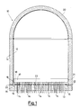
- a distributor casing 10 of the type fitting to the head of tube nests for heat exchangers comprises according to the invention, as can be seen in figure 1, a cylindrical portion 11 fitted with a lining consisting of a suitably shaped sheet 12 of corrosion-proof material, for example titanium-plated steel.
- a disc-shaped tube plate 13 carrying a plurality of tubes 14 is made substantially flat and explosion cladded on its central area 23 with titanium. Said plate is butt welded to the cylindrical portion 11 (reference 22 indicates the weld bead between the parts).
- the upper part of the casing is closed by a dome-shaped section 20 made and connected to the cylindrical portion according to the known technique and is also covered with titanium according to the known method.
- conduits and devices also made according to known techniques and consequently not shown or described herein, to enable the casing to carry out the function for which it is designed.
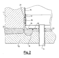
- the tube plate is provided with a semicircular section annular groove 19 in correspondence with the internal perimeter of the cylindrical wall, with its concavity substantially tangent to the seam between the plate 13 and the wall 11.
- a titanium insert 16 is positioned and welded between the edge of the lateral lining and the seam itself in correspondence with a step 21 on the wall 11. Said step serves the purpose of bringing the external surface of the coupling 15 up to the same level as that of the lining 12, which is of a different thickness.
- Titanium butt straps 17, 18 are positioned and welded between the cylindrical wall and the coupling 15 and between the coupling 15 and the tube plate so as to ensure continuity of the titanium lining also in correspondence with the weld and couplings between said parts.
- the coupling 15, insert 16 and butt straps 17, 18 may be made in radially cut segments, as can be easily inferred by anyone expert in the art.
- connection between the tube plate and the cylindrical wall described herein offers numerous advantages which make it possible to produce high quality vessels.
- the tube plate By making the tube plate substantially flat in shape it can be uniformly cladded without damage to its outer edges during the cladding process, as occurs with tank-shaped tube plates made by means of the known technique.
- the shape of the coupling 15 enables the entire surface of the tube plate to be utilized for passage of the heat exchanger tubes, as far as the coupling, thereby making it possible to obtain distributor casings, with the same number of tube nests, with more limited dimensions than those obtainable with tank-shaped tube plates.
- titanium has been found to be the material most advantageously used for the lining, any other suitable corrosion-proof material can obviously be used.
Landscapes
- Engineering & Computer Science (AREA)
- Physics & Mathematics (AREA)
- Thermal Sciences (AREA)
- Mechanical Engineering (AREA)
- General Engineering & Computer Science (AREA)
- Chemical & Material Sciences (AREA)
- Chemical Kinetics & Catalysis (AREA)
- Heat-Exchange Devices With Radiators And Conduit Assemblies (AREA)
- Preventing Corrosion Or Incrustation Of Metals (AREA)
Priority Applications (1)
| Application Number | Priority Date | Filing Date | Title |
|---|---|---|---|
| AT89202729T ATE85697T1 (de) | 1988-11-03 | 1989-10-30 | Verteilergehaeuse fuer waermeaustauscher mit korrosionsbestaendigem ueberzug. |
Applications Claiming Priority (2)
| Application Number | Priority Date | Filing Date | Title |
|---|---|---|---|
| IT8822488A IT8822488A0 (it) | 1988-11-03 | 1988-11-03 | Cassa distributrice per scambiatore di calore con rivestimento anticorrosione. |
| IT2248888 | 1988-11-03 |
Publications (2)
| Publication Number | Publication Date |
|---|---|
| EP0367346A1 true EP0367346A1 (de) | 1990-05-09 |
| EP0367346B1 EP0367346B1 (de) | 1993-02-10 |
Family
ID=11196946
Family Applications (1)
| Application Number | Title | Priority Date | Filing Date |
|---|---|---|---|
| EP89202729A Expired - Lifetime EP0367346B1 (de) | 1988-11-03 | 1989-10-30 | Verteilergehäuse für Wärmeaustauscher mit korrosionsbeständigem Überzug |
Country Status (4)
| Country | Link |
|---|---|
| EP (1) | EP0367346B1 (de) |
| AT (1) | ATE85697T1 (de) |
| DE (1) | DE68904871T2 (de) |
| IT (1) | IT8822488A0 (de) |
Cited By (3)
| Publication number | Priority date | Publication date | Assignee | Title |
|---|---|---|---|---|
| DE4406852A1 (de) * | 1993-03-03 | 1994-09-08 | Nuovo Pignone Spa | Verbesserter Verteiler für einen Wärmeaustauscher mit antikorrosiver Auskleidung |
| FR2863906A1 (fr) * | 2003-12-22 | 2005-06-24 | Yves Rene Pierre Guibert | Appareil de concentration des effluents industriels par distillation a basse temperature sous vide de phase aqueuse |
| CN106052468A (zh) * | 2016-05-30 | 2016-10-26 | 安徽普瑞普勒传热技术有限公司 | 一种板式换热器的封头装置 |
Citations (6)
| Publication number | Priority date | Publication date | Assignee | Title |
|---|---|---|---|---|
| DE228406C (de) * | ||||
| FR745834A (fr) * | 1931-12-09 | 1933-05-17 | Brown | Dispositif pour protéger contre la corrosion les plaques tubulaires en fer des échangeurs de chaleur |
| US3365097A (en) * | 1966-02-25 | 1968-01-23 | Dow Chemical Co | Repair patch for lined vessels |
| DE3027768A1 (de) * | 1979-07-23 | 1981-02-19 | Sumitomo Light Metal Ind | Mit legierungen auf aluminiumbasis plattiertes material fuer waermeaustauscher |
| EP0082920A2 (de) * | 1981-12-24 | 1983-07-06 | Heraeus Elektroden GmbH | Metallbehälter, insbesondere für den chemischen Apparate-bau, und Verfahren zur Herstellung solcher Behälter |
| US4485960A (en) * | 1982-08-27 | 1984-12-04 | Westinghouse Electric Corp. | Joint for joining clad materials |
-
1988
- 1988-11-03 IT IT8822488A patent/IT8822488A0/it unknown
-
1989
- 1989-10-30 AT AT89202729T patent/ATE85697T1/de not_active IP Right Cessation
- 1989-10-30 EP EP89202729A patent/EP0367346B1/de not_active Expired - Lifetime
- 1989-10-30 DE DE8989202729T patent/DE68904871T2/de not_active Expired - Fee Related
Patent Citations (6)
| Publication number | Priority date | Publication date | Assignee | Title |
|---|---|---|---|---|
| DE228406C (de) * | ||||
| FR745834A (fr) * | 1931-12-09 | 1933-05-17 | Brown | Dispositif pour protéger contre la corrosion les plaques tubulaires en fer des échangeurs de chaleur |
| US3365097A (en) * | 1966-02-25 | 1968-01-23 | Dow Chemical Co | Repair patch for lined vessels |
| DE3027768A1 (de) * | 1979-07-23 | 1981-02-19 | Sumitomo Light Metal Ind | Mit legierungen auf aluminiumbasis plattiertes material fuer waermeaustauscher |
| EP0082920A2 (de) * | 1981-12-24 | 1983-07-06 | Heraeus Elektroden GmbH | Metallbehälter, insbesondere für den chemischen Apparate-bau, und Verfahren zur Herstellung solcher Behälter |
| US4485960A (en) * | 1982-08-27 | 1984-12-04 | Westinghouse Electric Corp. | Joint for joining clad materials |
Non-Patent Citations (2)
| Title |
|---|
| PATENT ABSTRACTS OF JAPAN, vol. 12, no. 260 (M-720)[3107], 21st July 1988, page 92 M 720; & JP-A-63 41 795 (KOBE STEEL LTD) 23-02-1988 * |
| PATENT ABSTRACTS OF JAPAN, vol. 6, no. 13 (M-171)[1106], 13th November 1982, page 134 M 171; & JP-A-57 130 795 (MITSUBISHI JUKOGYO K.K.) 13-08-1982 * |
Cited By (6)
| Publication number | Priority date | Publication date | Assignee | Title |
|---|---|---|---|---|
| DE4406852A1 (de) * | 1993-03-03 | 1994-09-08 | Nuovo Pignone Spa | Verbesserter Verteiler für einen Wärmeaustauscher mit antikorrosiver Auskleidung |
| FR2702271A1 (fr) * | 1993-03-03 | 1994-09-09 | Nuovo Pignone Ind Mec | Distributeur perfectionné pour échangeur de chaleur, comportant un garnissage anticorrosion. |
| AT402971B (de) * | 1993-03-03 | 1997-10-27 | Nuovo Pignone Spa | Verteiler für einen wärmeaustauscher |
| DE4406852C2 (de) * | 1993-03-03 | 1998-10-08 | Nuovo Pignone Spa | Verteiler für einen Wärmeaustauscher |
| FR2863906A1 (fr) * | 2003-12-22 | 2005-06-24 | Yves Rene Pierre Guibert | Appareil de concentration des effluents industriels par distillation a basse temperature sous vide de phase aqueuse |
| CN106052468A (zh) * | 2016-05-30 | 2016-10-26 | 安徽普瑞普勒传热技术有限公司 | 一种板式换热器的封头装置 |
Also Published As
| Publication number | Publication date |
|---|---|
| ATE85697T1 (de) | 1993-02-15 |
| DE68904871T2 (de) | 1993-05-27 |
| DE68904871D1 (de) | 1993-03-25 |
| IT8822488A0 (it) | 1988-11-03 |
| EP0367346B1 (de) | 1993-02-10 |
Similar Documents
| Publication | Publication Date | Title |
|---|---|---|
| EP0113748B1 (de) | Verfahren zur auskleidung einer öffnung in einer endplatte eines wärmetauschers und platte mit auskleidung einer öffnung | |
| CN1073488C (zh) | 工业设备中高压或中压部分装置的修复方法和修复的装置 | |
| US3729812A (en) | Manufacture of thin-walled containers | |
| US2631015A (en) | Continuous helical liner for vessels | |
| GB2024166A (en) | Freight containers | |
| EP0367346A1 (de) | Verteilergehäuse für Wärmeaustauscher mit korrosionsbeständigem Überzug | |
| US2384324A (en) | Method of making hot-water tanks | |
| GB2134203A (en) | Pipe joints-explosive welding | |
| NO164199B (no) | Mikroboelgeovn. | |
| EP0395080B1 (de) | Reaktionsbehälter | |
| US3258068A (en) | Shell and tube heat exchanger | |
| US1799234A (en) | Lining for metal parts of oil-cracking apparatus | |
| US2222079A (en) | Method of testing vessel liners | |
| US4193529A (en) | Method for interconnecting dissimilar metals welding to an explosively bonded bimetallic coupling | |
| US4889105A (en) | Water heater construction and method of manufacture | |
| KR890002972B1 (ko) | 클래드 부품을 사용하는 라이닝 방법과 클래드 부품 | |
| US3349951A (en) | Connections for alloy lined vessels | |
| US3895734A (en) | Thin-walled containers | |
| US3651558A (en) | Method of repairing a ceramic-lined nozzle | |
| US2354532A (en) | Hot water tank construction | |
| EP0156228B1 (de) | Wassererhitzerkonstruktion und Verfahren zur Herstellung | |
| EP0042887A1 (de) | Kraftstofftank, insbesondere Flüssiggastank für ein Fahrzeug | |
| US3211477A (en) | Clamping device | |
| EP0169632B1 (de) | Verbindung zwischen Endkammer und Endplatte | |
| USRE28875E (en) | Manufacture of thin-walled containers |
Legal Events
| Date | Code | Title | Description |
|---|---|---|---|
| PUAI | Public reference made under article 153(3) epc to a published international application that has entered the european phase |
Free format text: ORIGINAL CODE: 0009012 |
|
| AK | Designated contracting states |
Kind code of ref document: A1 Designated state(s): AT BE DE FR GB NL SE |
|
| 17P | Request for examination filed |
Effective date: 19901025 |
|
| 17Q | First examination report despatched |
Effective date: 19910529 |
|
| GRAA | (expected) grant |
Free format text: ORIGINAL CODE: 0009210 |
|
| RAP3 | Party data changed (applicant data changed or rights of an application transferred) |
Owner name: FBM-HUDSON ITALIANA S.P.A. |
|
| AK | Designated contracting states |
Kind code of ref document: B1 Designated state(s): AT BE DE FR GB NL SE |
|
| PG25 | Lapsed in a contracting state [announced via postgrant information from national office to epo] |
Ref country code: SE Effective date: 19930210 |
|
| REF | Corresponds to: |
Ref document number: 85697 Country of ref document: AT Date of ref document: 19930215 Kind code of ref document: T |
|
| REF | Corresponds to: |
Ref document number: 68904871 Country of ref document: DE Date of ref document: 19930325 |
|
| ET | Fr: translation filed | ||
| PLBE | No opposition filed within time limit |
Free format text: ORIGINAL CODE: 0009261 |
|
| STAA | Information on the status of an ep patent application or granted ep patent |
Free format text: STATUS: NO OPPOSITION FILED WITHIN TIME LIMIT |
|
| 26N | No opposition filed | ||
| PGFP | Annual fee paid to national office [announced via postgrant information from national office to epo] |
Ref country code: BE Payment date: 19941011 Year of fee payment: 6 |
|
| PGFP | Annual fee paid to national office [announced via postgrant information from national office to epo] |
Ref country code: DE Payment date: 19941013 Year of fee payment: 6 |
|
| PGFP | Annual fee paid to national office [announced via postgrant information from national office to epo] |
Ref country code: GB Payment date: 19941020 Year of fee payment: 6 |
|
| PGFP | Annual fee paid to national office [announced via postgrant information from national office to epo] |
Ref country code: FR Payment date: 19941024 Year of fee payment: 6 |
|
| PGFP | Annual fee paid to national office [announced via postgrant information from national office to epo] |
Ref country code: NL Payment date: 19941031 Year of fee payment: 6 Ref country code: AT Payment date: 19941031 Year of fee payment: 6 |
|
| PG25 | Lapsed in a contracting state [announced via postgrant information from national office to epo] |
Ref country code: GB Effective date: 19951030 Ref country code: AT Effective date: 19951030 |
|
| PG25 | Lapsed in a contracting state [announced via postgrant information from national office to epo] |
Ref country code: BE Effective date: 19951031 |
|
| BERE | Be: lapsed |
Owner name: FBM-HUDSON ITALIANA S.P.A. Effective date: 19951031 |
|
| PG25 | Lapsed in a contracting state [announced via postgrant information from national office to epo] |
Ref country code: NL Effective date: 19960501 |
|
| GBPC | Gb: european patent ceased through non-payment of renewal fee |
Effective date: 19951030 |
|
| PG25 | Lapsed in a contracting state [announced via postgrant information from national office to epo] |
Ref country code: FR Effective date: 19960628 |
|
| PG25 | Lapsed in a contracting state [announced via postgrant information from national office to epo] |
Ref country code: DE Effective date: 19960702 |
|
| NLV4 | Nl: lapsed or anulled due to non-payment of the annual fee |
Effective date: 19960501 |
|
| REG | Reference to a national code |
Ref country code: FR Ref legal event code: ST |