EP0367225A2 - A glass window antenna for use in a motor vehicle - Google Patents
A glass window antenna for use in a motor vehicle Download PDFInfo
- Publication number
- EP0367225A2 EP0367225A2 EP89120192A EP89120192A EP0367225A2 EP 0367225 A2 EP0367225 A2 EP 0367225A2 EP 89120192 A EP89120192 A EP 89120192A EP 89120192 A EP89120192 A EP 89120192A EP 0367225 A2 EP0367225 A2 EP 0367225A2
- Authority
- EP
- European Patent Office
- Prior art keywords
- antenna
- glass window
- pair
- heating conductor
- power supply
- Prior art date
- Legal status (The legal status is an assumption and is not a legal conclusion. Google has not performed a legal analysis and makes no representation as to the accuracy of the status listed.)
- Granted
Links
Images


Classifications
-
- H—ELECTRICITY
- H01—ELECTRIC ELEMENTS
- H01Q—ANTENNAS, i.e. RADIO AERIALS
- H01Q1/00—Details of, or arrangements associated with, antennas
- H01Q1/12—Supports; Mounting means
- H01Q1/1271—Supports; Mounting means for mounting on windscreens
- H01Q1/1278—Supports; Mounting means for mounting on windscreens in association with heating wires or layers
Definitions
- the present invention relates to window glass antennas for motor vehicles and, more particularly to an antenna arrangement in which a defogging heater conductor formed on a window glass of a motor vehicle serves as an antenna for receiving radio signals.
- An antenna arrangement of this kind is known in the art.
- a leakage of the received signals to a direct current (DC) heater power supply or ground must be minimized.
- DC direct current
- the heating conductor antenna covers an FM broadcasting band only, choke coils having a relatively small inductance will suffice. However, such small coils will considerably decrease their impedance of radio signal leakage for an AM broadcasting band, thus reducing available antenna power in AM band.
- a separate FM antenna 6 is formed in a blank portion of the window 1 above the heater wires 2. It comprises a main antenna element 6a in the form of two parallel wires connected to each other in a substantial U shape, an auxiliary antenna element 6b disposed above and connected to the upper wire of the main antenna element 6a, another auxiliary antenna element 6c connected to the lower wire of the main antenna element 6a and facing the heater wires 2, and a folded element 6d bent back from the upper wire of the main antenna element and having a portion adjacent to the auxiliary antenna 6b.
- a feeding point 7 is formed on the folded portion 6d and connected to a feeder cable 8 for supplying an FM reception signal to an FM radio tuner through a DC cut capacitor 9.
- Fig. 2 illustrates another example of the prior art window glass antenna arrangement.
- Figs. 1 and 2 like references refer to like parts.
- the top FM antenna 36 includes a coupling element 37 along the uppermost heating wire 2 for coupling with the heater conductor 10, and a feeding pad 7 connected to a feeder cable 35 for carrying AM and FM signals to an AM/FM tuner.
- the bottom FM antenna 38 also includes a coupling element 39 along the lowermost heating wire for coupling with signals from the heater conductor 10 and a feeding pad 40 connected to another feeder cable 41 for supplying the AM/FM tuner with AM and FM signals received in the heater conductor 10 and the bottom FM antenna conductor 38.
- An object of the present invention is to provide a glass window antenna for use in a motor vehicle capable of making best use of the space or surface of a vehicle window (e.g., rear window) for defogging and antenna purposes.
- a vehicle window e.g., rear window
- a specific object of the invention is to provide a glass window antenna for use in a motor vehicle in which a heating conductor formed on a glass window can serve as an antenna element with a satisfactory reception sensitivity to radio waves covering a relatively wide range of radio frequencies, e.g., both AM and FM broadcasting bands.
- Another object of the invention is to provide a glass window antenna for use in a motor vehicle capable of minimizing leakage of received radio signals from antenna elements (e.g., heating conductor) formed on a glass window to thereby maximize an available antenna gain for a radio receiver.
- antenna elements e.g., heating conductor
- a glass window antenna for use in a motor vehicle which comprises a heating conductor formed on a glass window, choke coils each connected in a different one of a pair of power supply lines supplying a heating current to the heating conductor, and a capacitive circuit connected to the pair of power supply lines at a position between the choke coils and the heating conductor.
- the combination of the capacitive circuit and the choke coils serves as an optimal impedance element which effectively prevents the radio signals received in the heating conductor from passing or leaking through the choke coils while allowing passing the heating current to the heating conductor through the choke coils and the power supply lines.
- the capacitive circuit serves to vary or adjust the effective length of the antenna because it is connected across the pair of power supply lines that are connected to the heating conductor receiving radio waves.
- the choke coils may be magnetically coupled to each other in a nonsaturated state.
- Each choke coil may have a relatively large inductance.
- the power supply lines may carry a direct current to heat the heating conductor.
- a feeder connected to the heating conductor for carrying signals (e.g., covering both AM and FM bands) received in the heating conductor as being available for a radio receiver such as AM and FM tuners.
- the heating conductor may be arranged in a pattern of strip conductors or wire over a surface of the glass window.
- a glass window antenna for use in a motor vehicle comprising a heating conductor formed on a glass window, a pair of antenna elements arranged on the glass window in such a manner that one of the pair of antenna elements bears a substantial symmetry with the other of the pair of antenna element in which a first end the heating conductor is connected to a first end of the one antenna element while a second end of the heating conductor is connected to a first end of the other antenna element and in which respective second ends of the pair of the antenna elements faces each other.
- an additional antenna element may be formed on the glass window between the pair of antenna elements. According to tests, with the additional antenna element, the antenna gain is made flat over an FM band.
- the additional antenna element may be regarded as a coupling means for coupling the pair of antenna elements with each other with respect to signals generated or carried therein.
- the additional antenna element may be in alignment with and spaced from the pair of antenna elements.
- a glass window antenna for use in a motor vehicle which comprises a heating conductor formed on a glass window, choke coils, a pair of power supply lines for connecting the choke coils to the heating conductor to supply a heating current to the heating conductor, a pair of antenna elements formed on the glass window, connected to the heating conductor and having a substantially symmetrical relationship with each other with respect to the heating conductor, and a capacitive circuit connected across the power supply lines.
- the capacitive circuit may comprise a capacitor having a capacitance preferably between 5 pico and 0.5 micro farads, and most preferably between 30 and 200 pico farads.
- FIG. 3 there is shown a front view of a rear glass window for a motor vehicle mounting a radio receiving antenna function in conjunction with associated circutry shown in a schematic diagram in accordance with an embodiment of the invention.
- a heating conductor 10 is arranged in a defogging area of a rear glass window 1. When a heating current is supplied to the heating conductor 10, it is heated to defog the glass surface.
- a pair of antenna elements 23 and 24 is formed on a top margin of the glass window 1 and bears a symmetrical relationship with each other with respect to a central axis of the heating conductor 10.
- Choke coils 16a and 16b are respectively inserted into power supply lines 17 and 18.
- the choke coils are magnetically coupled with each other in a nonsaturated state.
- the opposite end of the choke coil 16a from the heater conductor 10 is connected to a direct current (DC) power supply at is positive terminal indicated by +B in Fig. 3 and it is also connected to a ground via a capacitor 20 for a surge or noise absorber while the opposite end of the choke coil 16 from the heater conductor 10 is grounded.
- DC direct current
- the capacitor 27 serves to compensate for a change in the effective length of the heating conductor 10 resulting from the connection of the heating power supply lines 17 and 18 thereto.
- the capacitor 27 will compensate for an increase in the leakage of radio signals of higher frequencies such as FM broadcasting band through the choke coils 16a and 16b from the heating conductor 10 due to the capacitance in the choke coils which causes the impedance across each choke coil 16a, 16b to be decreased for higher frequencies. Therefore, with the capacitor 27, the arrangement of Fig. 3 can provide an increased antenna gain for a band of higher frequencies such as FM band covering at least 76 to 90 MHz while maintaining a satisfactory antenna gain for another band of relatively low radio frequencies such as AM broadcasting band covering at least 600 to 1600 KHz.
- a test of reception sensitivity of the antenna arrangement with the capacitor 27 has indicated a greatly improved antenna gain for the entire range of FM broadcasting band as hown in a solid curve B in Fig. 4 as compared with the curve A measured without the capacitor 27.
- Fig. 5 shows test results of reception sensitivity to the FM band using several different capacitive values of the capacitor 27. As noted, the peak of the antenna gain shifts to lower frequencies as the capacitance increases.
- the symmetrical antenna elements 23 to 25 is expected to improve the radio signal condition in the heating conductor 10.
- the antenna elements 23 to 25 did improved antenna characteristics for FM broadcasting band.
- the addition of the antenna elements 23 to 25 makes a significant improvement of reception sensitivity for FM band over the arrangement without the antenna elements 23 to 25.
- the reception sensitivity with the antenna elements 23 to 25 are noted as good as that obtained from pillar antennas.
- the antenna elements 23 - 25 can serve to improve antenna directivity.
- Fig. 10 shows antenna directivity measured with the arrangement of Fig. 3 with the antenna elements 23 - 25, using horizontally polarized radio waves at 76, 78, 80, 82, 84, 86, 88, 90 MHz, respectively.
- a substantially circular or omnidirectional antenna directivity was obtained i.e., the antenna gain was substantially constant irrespective of the direction of the radio wave in relation to the antenna.
- Fig. 11 shows antenna directivity of the arrangement of Fig. 3 measured with vertically polarized radio waves in FM band.
- the resultant antenna directivity has indicated an ⁇ curve with the minimum antenna gain when the radio wave is applied in forward and backward direction in relation to the antenna.
- This is in contrast to the prior art glass antenna FM antenna which provide antenna directivity of an 8 shape with the minimum antenna gain when the radio wave is applied in a direction horizontally and laterally crossing the antenna. Therefore, a combination of the prior art antenna with the arrangement of Fig. 3 will constitute a most useful diversity antenna system with optimized antenna directivity for vertically polarized radio waves.
- Fig. 12 shows maximum antenna reception sensitivity
- Fig. 13 shows average antenna reception sensitivity, both measured with the arrangement of Fig. 3 using vertically polarized radio waves in FM band of 75 to 90 MHz.
- the resultant sensitivity is as good as that obtained with horizontally polarized radio waves (see Figs 7 and 8). Therefore, the addition of the antenna elements 23 to 25 serves to improve radio reception sensitivity to FM band of vertically polarized radio signals as well.
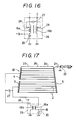
- Figs. 16 to 19 show modifications of the embodiments of Fig. 3 in respect of the location and connection of the capacitor 27.
- the capacitor is connected across taps 28 and 29 provided in the respective choke coils 16a and 16b.
- auxiliary terminals or connecting pads 32 and 33 may be provided near the end 30 and 31 of the buses 3 and 4 to connect the capacitor 27 between the pads 32 and 33.
- Fig. 20A - 20G, 21 and 22 show other modifications of the embodiment of Fig. 3 in respect of the antenna elements 23 - 25.
- the second antenna element 25 is omitted so that the antenna elements 23 and 24 directly faces each other.
- a pair of antenna elements 25 is employed which vertically spaced from each other and sandwiches ends of the antenna elements 23 and 24 in the space.
- Fig. 20C instead of the antenna element 25, vertical wires 31a and 31b are formed at ends of the antenna elements 23 and 24 to couple them in a capacitive manner.
- a plurality of parallel wires 23 - 25 are employed to increase the associated capacitance so that the arrangement of Fig. 20D will be useful for a broad band antenna.
- a plurality of parallel and staggered or offset wires 23 - 25 are employed to improve the frequency characteristic.
- each antenna element 25 in Figs. 20D and 20E may be omitted.
- each power supply bus 3, 4 is made short and some heating wires connected to the buses 3 and 4 extend obliquely at part hereof as shown.
- an equivalent length of the buses 3 and 4 is indicated by l.
- the antenna elements 23 - 25 are formed on the bottom margin of the window 1 while in Fig. 22, a first set of antenna elements 23 - 25 is formed on the top margin of the window 1 and a second set of antenna elements 23 and 24 is formed on the bottom margin of the window.
Abstract
Description
- The present invention relates to window glass antennas for motor vehicles and, more particularly to an antenna arrangement in which a defogging heater conductor formed on a window glass of a motor vehicle serves as an antenna for receiving radio signals.
- An antenna arrangement of this kind is known in the art. In order to assure that a sufficient amount of radio signals received in such a heating conductor be available for a radio receiver or tuner, a leakage of the received signals to a direct current (DC) heater power supply or ground must be minimized. To this end, it was proposed to connect choke coils in the heating power supply lines so that the heating conductor will be floated or isolated from the heater power supply in high frequencies while allowing the heating rower of DC current to pass through the choke coils. If the heating conductor antenna covers an FM broadcasting band only, choke coils having a relatively small inductance will suffice. However, such small coils will considerably decrease their impedance of radio signal leakage for an AM broadcasting band, thus reducing available antenna power in AM band. On the other hand, if a large inductance of choke coils is employed, this will give a satisfactory antenna gain for AM band but render a poor antenna reception sensitivity to FM band because of an increased parasitic capacitance in such high inductance choke coils. In this view, the prior art has adopted an arrangement in which choke coils associated with a defogging heating conductor is made to have a relatively large inductance so that the heating conductor will serve only as an AM antenna. Separate antenna conductor elements are formed on the same window as that with the heating conductor to provide an FM antenna.
- Fig. 1 shows an example of the prior art window glass antenna of this type. The antenna is arranged such that a large number of heater wires or
strip conductors 2 constituting a defoggingheater conductor 10 and serving as an AM antenna are formed in a defogging area of arear glass window 1. The heater wires are subdivided into upper and lower wire groups which are powered frompower supply buses bus 5 is disposed along and commonly connects second or remote ends of the upper and lower wire groups to complete a heating current path. Since theheater wires 2 are used as an AM broadcast band reception antenna, afeeder cable 13 such as a coaxial cable is connected to afeeding point 12 provided in the connectingbus 5. Thefeeder cable 13 carries the received signal to an AM radio tuner mounted in the motor vehicle through aDC cut capacitor 14. - A
separate FM antenna 6 is formed in a blank portion of thewindow 1 above theheater wires 2. It comprises amain antenna element 6a in the form of two parallel wires connected to each other in a substantial U shape, anauxiliary antenna element 6b disposed above and connected to the upper wire of themain antenna element 6a, anotherauxiliary antenna element 6c connected to the lower wire of themain antenna element 6a and facing theheater wires 2, and a foldedelement 6d bent back from the upper wire of the main antenna element and having a portion adjacent to theauxiliary antenna 6b. Afeeding point 7 is formed on the foldedportion 6d and connected to afeeder cable 8 for supplying an FM reception signal to an FM radio tuner through aDC cut capacitor 9. - A main DC power supply feeds a heating current to the
power supply buses choke coils choke coil 16a connected to a main power +B is negatively coupled to thechoke coil 16b connected to a ground so that magnetic fluxes generated by the respective heating currents cancel each other within a core. Therefore, the core having a small volume can be operated in a nonsaturated state. Adecoupling capacitor 20 is connected between a ground and a line connected to the main power +B to prevent power source noise from being superposed on the reception signal. - Fig. 2 illustrates another example of the prior art window glass antenna arrangement. In Figs. 1 and 2, like references refer to like parts. In this example of Fig. 2, two
FM antennas window 1 above and below theheating conductor 10 as an AM antenna, respectively. Thetop FM antenna 36 includes acoupling element 37 along theuppermost heating wire 2 for coupling with theheater conductor 10, and afeeding pad 7 connected to afeeder cable 35 for carrying AM and FM signals to an AM/FM tuner. Thebottom FM antenna 38 also includes acoupling element 39 along the lowermost heating wire for coupling with signals from theheater conductor 10 and afeeding pad 40 connected to anotherfeeder cable 41 for supplying the AM/FM tuner with AM and FM signals received in theheater conductor 10 and the bottomFM antenna conductor 38. - As noted from the foregoing, the prior art requires a separate antenna element or elements for receiving FM band signals in addition to the heater conductor because the heater conductor only serves as an AM antenna. Such separate antenna element thus requires a relatively wide space for its mounting, as wide as about 120 to 150 mm above and/or below the heater conductor. Therefore, the prior art antenna arrangement is applicable only to a vehicle window glass having a large space; in small-sized cars such as two-box car, the rear window glass is limited in size, and further limited when it is mounted relatively up-right in the vehicle so that there is only a small top or bottom margin left in available for mounting an FM antenna conductor, once the heating conductor is formed on such small vehicle window.
- Even in a motor vehicle having a relatively large window glass area and hence a large blank area, a TV broadcast reception antenna, an automobile telephone antenna, and the like are often formed in the blank portion. In this case, no further sufficient area is assured an FM antenna Therefore, even if the glass window area is large, a glass antenna capable of receiving FM programs cannot often be formed.
- An object of the present invention is to provide a glass window antenna for use in a motor vehicle capable of making best use of the space or surface of a vehicle window (e.g., rear window) for defogging and antenna purposes.
- A specific object of the invention is to provide a glass window antenna for use in a motor vehicle in which a heating conductor formed on a glass window can serve as an antenna element with a satisfactory reception sensitivity to radio waves covering a relatively wide range of radio frequencies, e.g., both AM and FM broadcasting bands.
- Another object of the invention is to provide a glass window antenna for use in a motor vehicle capable of minimizing leakage of received radio signals from antenna elements (e.g., heating conductor) formed on a glass window to thereby maximize an available antenna gain for a radio receiver.
- Another object of the invention is to provide a glass window antenna for use in a motor vehicle capable of providing desirable antenna characteristics without requiring a separate and FM dedicated antenna element which is a separate component from a heating conductor formed on a glass window and which consumes a considerable space of the glass window.
- In accordance with an aspect of the present invention, there is provided a glass window antenna for use in a motor vehicle which comprises a heating conductor formed on a glass window, choke coils each connected in a different one of a pair of power supply lines supplying a heating current to the heating conductor, and a capacitive circuit connected to the pair of power supply lines at a position between the choke coils and the heating conductor.
- With this arrangement, improved antenna characteristics (e.g. antenna gain for FM band) can be attained. It is expected that leakage of the signals generated in the heating conductor in response to radio waves is minimized because of the function of the capacitive circuit connected across the heating power supply lines. Therefore, the available radio signals for a radio receiver will be increased. Stated in another way, the combination of the capacitive circuit and the choke coils serves as an optimal impedance element which effectively prevents the radio signals received in the heating conductor from passing or leaking through the choke coils while allowing passing the heating current to the heating conductor through the choke coils and the power supply lines.
- Moreover, the capacitive circuit serves to vary or adjust the effective length of the antenna because it is connected across the pair of power supply lines that are connected to the heating conductor receiving radio waves.
- The choke coils may be magnetically coupled to each other in a nonsaturated state.
- Each choke coil may have a relatively large inductance.
- The power supply lines may carry a direct current to heat the heating conductor.
- For example, the choke coils have a relatively high impedance for a first band of frequencies (e.g., AM broadcasting band) and have a relatively low impedance for a second band of frequencies (e.g., FM broadcasting band) which is higher than the first band by at least one order of magnitude.
- There may be further provided a feeder connected to the heating conductor for carrying signals (e.g., covering both AM and FM bands) received in the heating conductor as being available for a radio receiver such as AM and FM tuners.
- The heating conductor may be arranged in a pattern of strip conductors or wire over a surface of the glass window.
- In accordance with another aspect of the invention, there is provided a glass window antenna for use in a motor vehicle comprising a heating conductor formed on a glass window, a pair of antenna elements arranged on the glass window in such a manner that one of the pair of antenna elements bears a substantial symmetry with the other of the pair of antenna element in which a first end the heating conductor is connected to a first end of the one antenna element while a second end of the heating conductor is connected to a first end of the other antenna element and in which respective second ends of the pair of the antenna elements faces each other.
- Measurement tests of an antenna arrangement of this type have indicated that it provides improved antenna characteristics, in particular, reception sensitivity to radio waves in an FM band. It is thought that the pair of antenna elements function to modify a condition such as electromagnetic field around the heater conductor so as to increase an available radio power therefrom.
- Preferably, an additional antenna element may be formed on the glass window between the pair of antenna elements. According to tests, with the additional antenna element, the antenna gain is made flat over an FM band. The additional antenna element may be regarded as a coupling means for coupling the pair of antenna elements with each other with respect to signals generated or carried therein.
- The additional antenna element may be in alignment with and spaced from the pair of antenna elements.
- An antenna feed point may be provided in the heating conductor for gathering radio signals received in the heating conductor and the pair of antenna elements.
- In accordance with a combined aspect of the invention, there is provided a glass window antenna for use in a motor vehicle which comprises a heating conductor formed on a glass window, choke coils, a pair of power supply lines for connecting the choke coils to the heating conductor to supply a heating current to the heating conductor, a pair of antenna elements formed on the glass window, connected to the heating conductor and having a substantially symmetrical relationship with each other with respect to the heating conductor, and a capacitive circuit connected across the power supply lines.
- The capacitive circuit may comprise a capacitor having a capacitance preferably between 5 pico and 0.5 micro farads, and most preferably between 30 and 200 pico farads.
- The above and other objects, features and advantages of the invention will be more apparent from the following description taken in conjunction with the drawings in which:
- Fig. 1 shows prior art vehicle glass window antenna together with associated electric circuitry;
- Fig. 2 shows another prior art vehicle glass window antenna with associated electric circuitry;
- Fig. 3 shows a vehicle glass window antenna together with associated electric circuitry in accordance with an embodiment of the invention;
- Fig. 4 is a graphic presentation of antenna reception sensitivity to FM band for the embodiment of Fig. 3 as compared with the sensitivity of an antenna arrangement without the
capacitor 27 in Fig. 3; - Fig. 5 is a graphic presentation of FM radio reception sensitivity for various values of the
capacitor 27 in Fig. 3; - Fig. 6 is a graphic presentation of relative antenna reception sensitivity to AM band with the embodiment of Fig. 3 as compared with a reference of the antenna arrangement without the
capacitor 27 in Fig. 3; - Fig. 7 is a graphic presentation of FM maximum reception sensitivity of the embodiment of Fig. 3 together with that of a pillar antenna and that of an antenna arrangement without the antenna elements 23 - 25 in Fig. 3;
- Fig. 8 is a graphic presentation of FM average reception sensitivity for the same antenna arrangements as those of Fig. 7;
- Fig. 9 is a graphic presentation of FM relative reception sensitivity for the embodiment of Fig. 3 and for the arrangement without the antenna elements 23 - 25 in Fig. 3, as normalized by the sensitivity of the pillar antenna;
- Fig. 10 is a graphic presentation of antenna directivity of the embodiment of Fig. 3 for radio frequencies in FM band with a horizontal polarity;
- Fig. 11 is a graphic presentation of antenna directivity of the embodiment of Fig. 3 for radio frequencies in FM band with a vertical polarity;
- Fig. 12 is a graphic presentation of FM maximum reception consisting of the embodiment of Fig. 3 as measured with vertically polarized radio waves in FM band;
- Fig. 13 is a graphic presentation of FM average reception sensitivity of the embodiment of Fig. 3 as measured with vertically polarized radio waves in FM band;
- Fig. 14 shows a glass window antenna in which the
auxiliary antenna element 25 in Fig. 3 is omitted; - Fig. 15 is a graphic presentation of FM reception sensitivity for the embodiment of Fig. 3 as compared with the sensitivity of the arrangement without the
auxiliary antenna element 25 in Fig. 3 and the sensitivity of the arrangement without any of the antenna elements 23 - 25 in Fig. 3; - Fig. 16 shows a modified location of the connection with the
capacitor 27 in the choke coil assembly; - Fig. 17 shows a glass window antenna arrangement in which the
capacitor 27 is connected at a modified location of the power supply lines; - Fig. 18 shows a modified connection of the
capacitor 27 as applied to a glass window antenna with a one-sided heating power feeding arrangement; - Fig. 19 shows a modified connection of the
capacitor 27 as applied to a glass window antenna similar to that shown in Fig. 18; - Figs. 20A - 20G show glass window antennas modified in respect of the antenna elements 23 - 25 in Fig. 3;
- Fig. 21 shows another glass window antenna modified with respect to the antenna elements 23 - 25 in Fig. 3; and
- Fig. 22 shows still another glass window antenna modified with respect to the antenna elements 23 - 25 in Fig. 3.
- Referring first to Fig. 3, there is shown a front view of a rear glass window for a motor vehicle mounting a radio receiving antenna function in conjunction with associated circutry shown in a schematic diagram in accordance with an embodiment of the invention.
- A
heating conductor 10 is arranged in a defogging area of arear glass window 1. When a heating current is supplied to theheating conductor 10, it is heated to defog the glass surface. Theheating conductor 10 haspower supply buses rear glass window 1, and thirteenheater wires 2 spaced at equal intervals of a = 31 mm from one another and connected between thepower supply buses antenna elements glass window 1 and bears a symmetrical relationship with each other with respect to a central axis of theheating conductor 10. The left-hand antenna elements 23 has a left and connected to the upper end of thepower supply bus 3 of theheating conductor 10 while the right-hand antenna element 24 has a right end connected to the upper end of thepower supply bus 4 of theheating conductor 10. Theseantenna elements uppermost heater wire 2 and spaced therefrom by an interval of 31 mm. The other or free ends of theantenna elements rear glass window 1. Anauxiliary antenna wire 25 is formed between the other ends of theantenna elements wires heating conductor 10. Therefore, an appropriate choice of the dimensions of the antenna elements will optimize antenna reception sensitivity of theheating conductor 10 to an FM broadcasting band. - Sizes d to g of the respective parts in Fig. 3 are given as follows: d = 10 mm; e = 28 mm; f = 895 mm; and g = 1,030 mm.
- A feed point or
pad 11 is provided in theheating conductor 10, here, at the bottom of the right-handpower supply bus 4. Thefeed pad 11 gathers radio signals covering at least AM and FM broadcasting bands, as received in theheating conductor 10 and thesymmetrical antenna elements 23 to 25. Afeeder cable 22 is in the form of a coaxial cable is connected to thefeeder pad 11 via acapacitor 21 to carry the signals to radio receiving circuitry such as AM and FM tuners (not shown). - Choke coils 16a and 16b are respectively inserted into
power supply lines - The opposite end of the
choke coil 16a from theheater conductor 10 is connected to a direct current (DC) power supply at is positive terminal indicated by +B in Fig. 3 and it is also connected to a ground via acapacitor 20 for a surge or noise absorber while the opposite end of the choke coil 16 from theheater conductor 10 is grounded. - The inductance of the choke coils 16a and 16b are preferably large to improve reception sensitivity to an AM broadcast band. However, this also makes large the capacitances in the choke coils 16a and 16b so that for higher frequencies such as FM broadcasting band, an impedance across each of the choke coil is decreased, thereby degrading antenna reception sensitivity. For example, with a trodial core type choke oil having an inductance of 980 mH as each
choke coil - In this view and in accordance with the invention, there is provided a
capacitor 27 connected across thepower supply lines heating conductor 10, as indicated within ablock 26 in Fig. 3. - The
capacitor 27 serves to compensate for a change in the effective length of theheating conductor 10 resulting from the connection of the heatingpower supply lines capacitor 27 will compensate for an increase in the leakage of radio signals of higher frequencies such as FM broadcasting band through the choke coils 16a and 16b from theheating conductor 10 due to the capacitance in the choke coils which causes the impedance across eachchoke coil capacitor 27, the arrangement of Fig. 3 can provide an increased antenna gain for a band of higher frequencies such as FM band covering at least 76 to 90 MHz while maintaining a satisfactory antenna gain for another band of relatively low radio frequencies such as AM broadcasting band covering at least 600 to 1600 KHz. - A test of reception sensitivity of the antenna arrangement with the
capacitor 27 has indicated a greatly improved antenna gain for the entire range of FM broadcasting band as hown in a solid curve B in Fig. 4 as compared with the curve A measured without thecapacitor 27. - Fig. 5 shows test results of reception sensitivity to the FM band using several different capacitive values of the
capacitor 27. As noted, the peak of the antenna gain shifts to lower frequencies as the capacitance increases. - The optimal capacitance of the
capacitor 27 depends considerably on the electrical characteristics of the choke coils which is a function of their type, form, size and so an. According to tests, however, the capacitor with a capacitance between approximately 5 pico farads to 0.1 micro farads served to improve the reception sensitivity to FM band of 76 to 90 MHz. In particular, a capacitance between 30 to 200 pico farads yielded most desirable results. - The addition of the
capacitor 27 maintains reception sensitivity to AM broadcasting band of 600 to 1600 KHz as demonstrated in Fig. 6 which shows a relative reception sensitivity with thecapacitor 27 as compared with that of nocapacitor 27, normalized by zero decibel in Fig. 6. - As described earlier, the
symmetrical antenna elements 23 to 25 is expected to improve the radio signal condition in theheating conductor 10. - According to tests, the
antenna elements 23 to 25 did improved antenna characteristics for FM broadcasting band. - In Fig. 7 to 9 showing reception sensitivity to FM band of 75 to 90 MHz, each curve A was obtained when the
antenna elements 23 to 25 were omitted from the arrangement of Fig. 3. each curve B was obtained with theantenna elements 23 to 25, and each curve C was obtained with a pillar or rod antenna of 920 millimeters. Fig. 7 shows maximum reception sensitivity while Fig. 8 shows averaged reception sensitivity, and Fig. 9 shows a relative reception sensitivity with and withoutantenna elements 23 to 25 in relation to zero decibel reference of the pillar antenna. - As noted from Figs. 7 to 9, the addition of the
antenna elements 23 to 25 makes a significant improvement of reception sensitivity for FM band over the arrangement without theantenna elements 23 to 25. The reception sensitivity with theantenna elements 23 to 25 are noted as good as that obtained from pillar antennas. - In addition, the antenna elements 23 - 25 can serve to improve antenna directivity. Fig. 10 shows antenna directivity measured with the arrangement of Fig. 3 with the antenna elements 23 - 25, using horizontally polarized radio waves at 76, 78, 80, 82, 84, 86, 88, 90 MHz, respectively. As noted, a substantially circular or omnidirectional antenna directivity was obtained i.e., the antenna gain was substantially constant irrespective of the direction of the radio wave in relation to the antenna.
- In some circumstances, such as in Japanese local radio stations and in U.S.A, vertically polarized radio waves are used in place of horizontally polarized radio waves. It has been formed that the antenna arrangement of Fig. 3 is also effective to such vertically polarized radio systems.
- Fig. 11 shows antenna directivity of the arrangement of Fig. 3 measured with vertically polarized radio waves in FM band. As noted, the resultant antenna directivity has indicated an ∞ curve with the minimum antenna gain when the radio wave is applied in forward and backward direction in relation to the antenna. This is in contrast to the prior art glass antenna FM antenna which provide antenna directivity of an 8 shape with the minimum antenna gain when the radio wave is applied in a direction horizontally and laterally crossing the antenna. Therefore, a combination of the prior art antenna with the arrangement of Fig. 3 will constitute a most useful diversity antenna system with optimized antenna directivity for vertically polarized radio waves.
- Fig. 12 shows maximum antenna reception sensitivity and Fig. 13 shows average antenna reception sensitivity, both measured with the arrangement of Fig. 3 using vertically polarized radio waves in FM band of 75 to 90 MHz. The resultant sensitivity is as good as that obtained with horizontally polarized radio waves (see Figs 7 and 8). Therefore, the addition of the
antenna elements 23 to 25 serves to improve radio reception sensitivity to FM band of vertically polarized radio signals as well. - In Fig. 14, there is shown a glass window antenna in which the auxiliary
coupling antenna element 25 in Fig. 3 is omitted. Without theelement 25, antenna reception sensitivity to FM band was somewhat concaved as indicated by a curve B in Fig. 15 in which the curve C was measured with theelement 25 and the curve A was obtained without any of theantenna elements 23 to 25. As noted, the addition of theauxiliary antenna element 25 disposed between theantenna elements - Figs. 16 to 19 show modifications of the embodiments of Fig. 3 in respect of the location and connection of the
capacitor 27. - In Fig. 16, the capacitor is connected across taps 28 and 29 provided in the
respective choke coils - In Fig. 17, the
capacitor 27 is connected across the heatingpower supply lines choke coil assembly 26 to theheating conductor 10. An appropriate choice of the location of thepower supply lines capacitor 27 is connected thereacross may optimize the antenna characteristics. - In the case of Fig. 18 in which a heating current is supplied to only one side of the
rear window 1, here,power supply buses power supply buses capacitor 27 may readily be connected between the adjacent ends 30 and 31 of thepower supply buses pads end buses capacitor 27 between thepads - Fig. 20A - 20G, 21 and 22 show other modifications of the embodiment of Fig. 3 in respect of the antenna elements 23 - 25.
- In Fig. 20A, the
second antenna element 25 is omitted so that theantenna elements - In Fig. 20B, a pair of
antenna elements 25 is employed which vertically spaced from each other and sandwiches ends of theantenna elements - In Fig. 20C, instead of the
antenna element 25,vertical wires 31a and 31b are formed at ends of theantenna elements - In Fig. 20D, a plurality of parallel wires 23 - 25 are employed to increase the associated capacitance so that the arrangement of Fig. 20D will be useful for a broad band antenna.
- In Fig. 20E, a plurality of parallel and staggered or offset wires 23 - 25 are employed to improve the frequency characteristic.
- Further, each
antenna element 25 in Figs. 20D and 20E may be omitted. - In Figs. 20F and 20G, in order to save conductive paste materials for the
power supply buses power supply bus buses buses - In Fig. 21, the antenna elements 23 - 25 are formed on the bottom margin of the
window 1 while in Fig. 22, a first set of antenna elements 23 - 25 is formed on the top margin of thewindow 1 and a second set ofantenna elements - This concludes the detailed description of the invention. However, many other modifications, variations and alternations will be obvious to one of ordinary skill in the art without deviating from the scope of the invention which should be solely limited by the appended claims.
Claims (24)
a pair of antenna elements (23, 24) formed on said glass window, connected to said heating conductor, and having a substantially symmetrical relationship with each other with respect to said heating conductor; and
a capacitive circuit (27) connected across said power supply lines.
choke coils (16a, 16b), and a pair of power supply lines (17, 18) extending between said choke coils and said heater for supplying a heating current to said heater, characterized by a circuit (27) connected across said of power supply lines and having an electric property such that for an entire frequency range of radio waves received by said antenna at said heater, a relatively low impedance is established across said pair of power supply lines as compared with an impedance across each of said choke coils.
Applications Claiming Priority (4)
| Application Number | Priority Date | Filing Date | Title |
|---|---|---|---|
| JP142518/88U | 1988-10-31 | ||
| JP14251888U JPH0262813U (en) | 1988-10-31 | 1988-10-31 | |
| JP155642/88U | 1988-11-30 | ||
| JP15564288U JPH0619205Y2 (en) | 1988-11-30 | 1988-11-30 | Window glass antenna |
Publications (3)
| Publication Number | Publication Date |
|---|---|
| EP0367225A2 true EP0367225A2 (en) | 1990-05-09 |
| EP0367225A3 EP0367225A3 (en) | 1990-08-08 |
| EP0367225B1 EP0367225B1 (en) | 1994-12-28 |
Family
ID=26474497
Family Applications (1)
| Application Number | Title | Priority Date | Filing Date |
|---|---|---|---|
| EP89120192A Expired - Lifetime EP0367225B1 (en) | 1988-10-31 | 1989-10-31 | A glass window antenna for use in a motor vehicle |
Country Status (3)
| Country | Link |
|---|---|
| US (1) | US5113195A (en) |
| EP (1) | EP0367225B1 (en) |
| DE (1) | DE68920277T2 (en) |
Cited By (5)
| Publication number | Priority date | Publication date | Assignee | Title |
|---|---|---|---|---|
| GB2266189A (en) * | 1992-04-08 | 1993-10-20 | Antiference Ltd | Vehicle antenna |
| US5831580A (en) * | 1993-12-29 | 1998-11-03 | Mazda Motor Corporation | Slot antenna having a slot portion formed in a vehicle mounted insulator |
| EP1760827A1 (en) * | 2005-09-01 | 2007-03-07 | Pantech & Curitel Communications Inc | Mobile communication terminal having electrostatic discharge protection function |
| FR3076169A1 (en) * | 2017-12-21 | 2019-06-28 | Psa Automobiles Sa | CORRELATED COMMON MODE MODE IMPEDANCE FILTER HEATING DEVICE FOR RADIOPHONIC WAVE RECEPTION ANTENNA GLASS |
| FR3076168A1 (en) * | 2017-12-21 | 2019-06-28 | Psa Automobiles Sa | DIFFERENTIAL FILTER HEATING DEVICE FOR A RADIOPHONIC WAVE RECEIVING ANTENNA GLASS |
Families Citing this family (9)
| Publication number | Priority date | Publication date | Assignee | Title |
|---|---|---|---|---|
| DE4401819A1 (en) * | 1994-01-22 | 1995-07-27 | Kolbe & Co Hans | Cable arrangement for active antenna combined with screen heater |
| DE29606416U1 (en) * | 1996-04-06 | 1996-06-27 | Mekra Rangau Plastics | Exterior rear-view mirrors for motor vehicles, in particular commercial vehicles |
| US5781160A (en) * | 1996-05-31 | 1998-07-14 | The Ohio State University | Independently fed AM/FM heated window antenna |
| USD428286S (en) * | 1998-05-29 | 2000-07-18 | Kimberly-Clark Worldwide | Dispenser adapter for coreless rolls of products |
| JP2000114839A (en) * | 1998-10-05 | 2000-04-21 | Harada Ind Co Ltd | Window glass antenna device for vehicle |
| DE10359223A1 (en) * | 2003-12-17 | 2005-07-21 | Robert Bosch Gmbh | Vehicle window antenna |
| CN101060193A (en) * | 2006-04-19 | 2007-10-24 | 旭硝子株式会社 | High frequency wave glass antenna for an automobile and rear window glass sheet for an automobile |
| CN103518324B (en) * | 2011-05-09 | 2016-06-15 | 株式会社村田制作所 | Impedance inverter circuit and communication terminal |
| WO2015019904A1 (en) * | 2013-08-05 | 2015-02-12 | 旭硝子株式会社 | Antenna device |
Citations (5)
| Publication number | Priority date | Publication date | Assignee | Title |
|---|---|---|---|---|
| FR2250329A5 (en) * | 1973-10-31 | 1975-05-30 | Saint Gobain | |
| DE3409876A1 (en) * | 1984-03-17 | 1985-09-19 | Robert Bosch Gmbh, 7000 Stuttgart | Heated-window antenna |
| EP0269924A2 (en) * | 1986-11-21 | 1988-06-08 | Harada Industry Co., Ltd. | Compensation amplifier for an automobile antenna |
| FR2608844A1 (en) * | 1986-12-19 | 1988-06-24 | Central Glass Co Ltd | VEHICLE WINDOW ANTENNA USING TRANSPARENT CONDUCTIVE FILM |
| EP0297813A2 (en) * | 1987-06-27 | 1989-01-04 | Nippon Sheet Glass Co., Ltd. | A vehicle receiving apparatus using a window antenna |
Family Cites Families (9)
| Publication number | Priority date | Publication date | Assignee | Title |
|---|---|---|---|---|
| US4063247A (en) * | 1976-10-07 | 1977-12-13 | Nippon Sheet Glass Co., Ltd. | Heater glass sheet with broad band receiver antennae |
| GB1600987A (en) * | 1977-08-17 | 1981-10-21 | Bsh Electronics Manchester Ltd | Electrical device to enable the heating element of an electrically heated motor vehicle window to be used as a radio transmitting aerial |
| JPS57188102A (en) * | 1981-05-15 | 1982-11-19 | Asahi Glass Co Ltd | Glass antenna for automobile |
| JPS61203702A (en) * | 1985-03-07 | 1986-09-09 | Asahi Glass Co Ltd | Antenna system for automobile |
| JPS6130102A (en) * | 1984-07-20 | 1986-02-12 | Nippon Sheet Glass Co Ltd | Antenna of window glass for automobile |
| JPS6173403A (en) * | 1984-09-19 | 1986-04-15 | Nissan Motor Co Ltd | Glass antenna for automobile |
| JPS61175010A (en) * | 1985-01-31 | 1986-08-06 | Hino Motors Ltd | Molding method |
| JPH0640769B2 (en) * | 1986-02-18 | 1994-06-01 | 株式会社スズテック | Strip seeding equipment for nursery boxes |
| JPS6326925A (en) * | 1986-07-18 | 1988-02-04 | Matsushita Electronics Corp | Magnetron |
-
1989
- 1989-10-26 US US07/427,587 patent/US5113195A/en not_active Expired - Fee Related
- 1989-10-31 EP EP89120192A patent/EP0367225B1/en not_active Expired - Lifetime
- 1989-10-31 DE DE68920277T patent/DE68920277T2/en not_active Expired - Fee Related
Patent Citations (5)
| Publication number | Priority date | Publication date | Assignee | Title |
|---|---|---|---|---|
| FR2250329A5 (en) * | 1973-10-31 | 1975-05-30 | Saint Gobain | |
| DE3409876A1 (en) * | 1984-03-17 | 1985-09-19 | Robert Bosch Gmbh, 7000 Stuttgart | Heated-window antenna |
| EP0269924A2 (en) * | 1986-11-21 | 1988-06-08 | Harada Industry Co., Ltd. | Compensation amplifier for an automobile antenna |
| FR2608844A1 (en) * | 1986-12-19 | 1988-06-24 | Central Glass Co Ltd | VEHICLE WINDOW ANTENNA USING TRANSPARENT CONDUCTIVE FILM |
| EP0297813A2 (en) * | 1987-06-27 | 1989-01-04 | Nippon Sheet Glass Co., Ltd. | A vehicle receiving apparatus using a window antenna |
Cited By (7)
| Publication number | Priority date | Publication date | Assignee | Title |
|---|---|---|---|---|
| GB2266189A (en) * | 1992-04-08 | 1993-10-20 | Antiference Ltd | Vehicle antenna |
| GB2266189B (en) * | 1992-04-08 | 1996-09-11 | Antiference Ltd | Vehicle antenna |
| US5831580A (en) * | 1993-12-29 | 1998-11-03 | Mazda Motor Corporation | Slot antenna having a slot portion formed in a vehicle mounted insulator |
| EP1760827A1 (en) * | 2005-09-01 | 2007-03-07 | Pantech & Curitel Communications Inc | Mobile communication terminal having electrostatic discharge protection function |
| US7307592B2 (en) | 2005-09-01 | 2007-12-11 | Pantech & Curitel Communications, Inc. | Mobile communication terminal having electrostatic discharge protection function |
| FR3076169A1 (en) * | 2017-12-21 | 2019-06-28 | Psa Automobiles Sa | CORRELATED COMMON MODE MODE IMPEDANCE FILTER HEATING DEVICE FOR RADIOPHONIC WAVE RECEPTION ANTENNA GLASS |
| FR3076168A1 (en) * | 2017-12-21 | 2019-06-28 | Psa Automobiles Sa | DIFFERENTIAL FILTER HEATING DEVICE FOR A RADIOPHONIC WAVE RECEIVING ANTENNA GLASS |
Also Published As
| Publication number | Publication date |
|---|---|
| EP0367225B1 (en) | 1994-12-28 |
| EP0367225A3 (en) | 1990-08-08 |
| US5113195A (en) | 1992-05-12 |
| DE68920277D1 (en) | 1995-02-09 |
| DE68920277T2 (en) | 1995-08-03 |
Similar Documents
| Publication | Publication Date | Title |
|---|---|---|
| KR0148588B1 (en) | Diversity glass antenna for an automobile | |
| US5289197A (en) | Pane antenna having an amplifier | |
| EP0418047B1 (en) | Glass window antenna for motor vehicle | |
| US6229493B1 (en) | Glass antenna device for vehicle | |
| US5905468A (en) | Glass antenna device for vehicles | |
| US5113195A (en) | Glass window antenna for use in a motor vehicle | |
| JP4941171B2 (en) | Glass antenna for vehicles | |
| US20050030235A1 (en) | Glass antenna for vehicle | |
| JPS61100004A (en) | Window glass for automobile with antenna element | |
| US5239302A (en) | Wave reception apparatus for a motor vehicle | |
| US6064345A (en) | Glass antenna device for an automobile | |
| JPH0113643B2 (en) | ||
| GB2309829A (en) | Vehicle on-screen antenna | |
| JPH11205023A (en) | Glass antenna system for vehicle use | |
| JPH09232845A (en) | Glass antenna for automobile | |
| JPH0756495Y2 (en) | Antenna device for car window | |
| JP3201710B2 (en) | Automotive window glass antenna | |
| EP0370714B2 (en) | A wave reception apparatus for a motor vehicle | |
| JPS63292702A (en) | Window glass for automobile with defogging heater | |
| JP3500697B2 (en) | Rear glass antenna for automobile TV band reception | |
| JPH0136335Y2 (en) | ||
| JPH0969712A (en) | Automobile glass antenna | |
| JP3648910B2 (en) | Vehicle antenna | |
| GB2316538A (en) | Vehicle windscreen antenna and heater element arrangement | |
| JP2001007624A (en) | On-glass antenna for automobile |
Legal Events
| Date | Code | Title | Description |
|---|---|---|---|
| PUAI | Public reference made under article 153(3) epc to a published international application that has entered the european phase |
Free format text: ORIGINAL CODE: 0009012 |
|
| AK | Designated contracting states |
Kind code of ref document: A2 Designated state(s): DE FR |
|
| PUAL | Search report despatched |
Free format text: ORIGINAL CODE: 0009013 |
|
| AK | Designated contracting states |
Kind code of ref document: A3 Designated state(s): DE FR |
|
| 17P | Request for examination filed |
Effective date: 19900803 |
|
| 17Q | First examination report despatched |
Effective date: 19920910 |
|
| GRAA | (expected) grant |
Free format text: ORIGINAL CODE: 0009210 |
|
| AK | Designated contracting states |
Kind code of ref document: B1 Designated state(s): DE FR |
|
| REF | Corresponds to: |
Ref document number: 68920277 Country of ref document: DE Date of ref document: 19950209 |
|
| ET | Fr: translation filed | ||
| PLBE | No opposition filed within time limit |
Free format text: ORIGINAL CODE: 0009261 |
|
| STAA | Information on the status of an ep patent application or granted ep patent |
Free format text: STATUS: NO OPPOSITION FILED WITHIN TIME LIMIT |
|
| 26N | No opposition filed | ||
| PGFP | Annual fee paid to national office [announced via postgrant information from national office to epo] |
Ref country code: FR Payment date: 20021008 Year of fee payment: 14 |
|
| PGFP | Annual fee paid to national office [announced via postgrant information from national office to epo] |
Ref country code: DE Payment date: 20021031 Year of fee payment: 14 |
|
| PG25 | Lapsed in a contracting state [announced via postgrant information from national office to epo] |
Ref country code: DE Free format text: LAPSE BECAUSE OF NON-PAYMENT OF DUE FEES Effective date: 20040501 |
|
| PG25 | Lapsed in a contracting state [announced via postgrant information from national office to epo] |
Ref country code: FR Free format text: LAPSE BECAUSE OF NON-PAYMENT OF DUE FEES Effective date: 20040630 |
|
| REG | Reference to a national code |
Ref country code: FR Ref legal event code: ST |