EP0367176A2 - Interior panel unit for permitting arrangement of cables and devices on room floor - Google Patents
Interior panel unit for permitting arrangement of cables and devices on room floor Download PDFInfo
- Publication number
- EP0367176A2 EP0367176A2 EP89120096A EP89120096A EP0367176A2 EP 0367176 A2 EP0367176 A2 EP 0367176A2 EP 89120096 A EP89120096 A EP 89120096A EP 89120096 A EP89120096 A EP 89120096A EP 0367176 A2 EP0367176 A2 EP 0367176A2
- Authority
- EP
- European Patent Office
- Prior art keywords
- floor
- members
- support members
- floor base
- base member
- Prior art date
- Legal status (The legal status is an assumption and is not a legal conclusion. Google has not performed a legal analysis and makes no representation as to the accuracy of the status listed.)
- Granted
Links
Images


Classifications
-
- E—FIXED CONSTRUCTIONS
- E04—BUILDING
- E04F—FINISHING WORK ON BUILDINGS, e.g. STAIRS, FLOORS
- E04F15/00—Flooring
- E04F15/02—Flooring or floor layers composed of a number of similar elements
- E04F15/024—Sectional false floors, e.g. computer floors
- E04F15/02447—Supporting structures
- E04F15/02494—Supporting structures with a plurality of base plates or like, each base plate having a plurality of pedestals upstanding therefrom to receive the floor panels
-
- E—FIXED CONSTRUCTIONS
- E04—BUILDING
- E04F—FINISHING WORK ON BUILDINGS, e.g. STAIRS, FLOORS
- E04F15/00—Flooring
- E04F15/02—Flooring or floor layers composed of a number of similar elements
- E04F15/02172—Floor elements with an anti-skid main surface, other than with grooves
-
- E—FIXED CONSTRUCTIONS
- E04—BUILDING
- E04F—FINISHING WORK ON BUILDINGS, e.g. STAIRS, FLOORS
- E04F15/00—Flooring
- E04F15/02—Flooring or floor layers composed of a number of similar elements
- E04F15/024—Sectional false floors, e.g. computer floors
- E04F15/02405—Floor panels
-
- H—ELECTRICITY
- H02—GENERATION; CONVERSION OR DISTRIBUTION OF ELECTRIC POWER
- H02G—INSTALLATION OF ELECTRIC CABLES OR LINES, OR OF COMBINED OPTICAL AND ELECTRIC CABLES OR LINES
- H02G3/00—Installations of electric cables or lines or protective tubing therefor in or on buildings, equivalent structures or vehicles
- H02G3/28—Installations of cables, lines, or separate protective tubing therefor in conduits or ducts pre-established in walls, ceilings or floors
- H02G3/283—Installations of cables, lines, or separate protective tubing therefor in conduits or ducts pre-established in walls, ceilings or floors in floors
- H02G3/285—Installations of cables, lines, or separate protective tubing therefor in conduits or ducts pre-established in walls, ceilings or floors in floors in modular floors, e.g. access floors
Definitions
- the present invention relates to an interior panel unit for permitting an arrangement of cables and devices on a room floor, the panel being used in an office or computer room to arrange an office-automation system.
- a conventional interior panel unit is available to realize an office-automation system by arranging power cables, signal cables, and various types of equipment on a room floor in an office or computer room, as described in U.S.P. Nos. 4,593,499 and 4,631 879.
- a given unit has blocks having shapes to be engaged with each other at a peripheral portion of a rectangular floor base installed on a foundation floor surface of a room, and blocks on each floor base are engaged with and coupled to each other to form each floor base on the foundation floor surface.
- a plurality of columnar members are mounted on a lower floor base installed on a foundation floor surface, and an upper floor base is supported by the columnar members with a gap corresponding to the height of each columnar member from the foundation floor surface.
- the latter unit has a structure wherein the lower floor base is installed on the foundation floor surface of the room and the upper floor base is supported and fixed through the plurality of columnar members.
- the adjacent lower floor bases are not coupled to each other. For this reason, the lower floor bases are not integrally coupled. Therefore, when the upper floor base is supported and fixed, stability and flatness of the upper floor surface consisting of the upper floor bases are degraded.
- an interior panel unit for creating an office-automation system by arranging power and signal cables and devices on a room floor comprising: floor base member to be installed on a foundation floor of a room; a plurality of fundamental support members fixed to upper surface of each of the floor base members, and having upper surfaces located at the same height from the upper surface of each floor base member; a plurality of connecting support members fixed to peripheral portions of each floor base member, and having upper surfaces located the same height as those of the fundamental support members; base joint members for connecting the connecting support members arranged on a plurality of floor base members in a state wherein the floor base members are installed on the same surface; and floor panel members brought into contact with the upper surfaces of the plurality of fundamental support members and the upper surfaces of the connecting support members to form a surface of the room floor and cooperating with the floor base members to define an internal space for installing cables and devices therein.
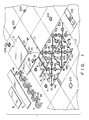
- Fig. 1 is a view showing an overall structure of an interior panel unit according to the present invention.
- the unit comprises floor base members 1 installed on a foundation floor surface 4 which defines a space of an office or computer room.
- Each floor base member 1 consists of a flexible synthetic resin (e.g., polypropylene) as a base material and comprises a rectangular plate having a ratio of a long side to a short side of 2 : 1 (e.g., 1 m : 500 mm).
- a flexible synthetic resin e.g., polypropylene
- Fundamental support members (fundamental columns) 11 for supporting a floor panel member 2 are located on the surface of the floor base member 1 except for the edge at predetermined intervals.
- Connecting support members (connecting columns) 12 are located at the edge except for corners of the upper surface of the floor base member 1.
- Connecting support members 13 are located at the corners of the upper surface of the floor base member 1.
- the support members 11 to 13 consist of a fire-retardant material such as foamed concrete and have the same height. It should be noted that 10 fundamental support members 11, 14 connecting support members 12 extending at the edge except for the corners, and four connecting support members 13 at the four corners are formed on each floor base member 1.
- Each fundamental support member 11 comprises a truncated cone and has a recess 11a at almost the center of the upper surface which is to contact the surface of the floor panel member 2.
- the recess 11a serves to prevent lateral shift of the floor panel member 2.
- Each connecting support member 12 extending at the edge except for the corners consists of a half piece which is obtained by cutting a truncated cone corresponding to the fundamental support member 11 in the vertical direction (i.e., a direction perpendicular to the surface of the floor base member 1).
- Each connecting support member 13 extending at each corner of each floor base member 1 comprises a 1/4 piece obtained by cutting the conical member corresponding to the fundamental support member 11 in the vertical directions.
- a slit-like vertical groove 11b is formed in the circumferential wall of each of the support members 11 to 13.
- the vertical grooves 11b are formed to support both ends of a vertical separator member 9 bridged between the adjacent ones of the support members 11 to 13.
- the vertical separator member 9 is a plate member for partitioning the horizontal space on the surface of the floor base member 1.
- V-shaped grooves (to be referred to as V-grooves hereinafter) 14a are formed in the surface of the floor base member 1 to connect the adjacent ones of the support members 11 to 13 with lines on a line obtained by connecting the middle points of the long sides and diagonal lines within each one of rectangles (squares) obtained by dividing the rectangular area into halves.
- Grooves 14b are formed to surround the 1/2 bottom arc of the fundamental support member 11 and the entire bottom arc of the connecting support member 12 extending at the edge, and a groove 14c is also formed to surround the entire bottom arc of the connecting support member 13 extending at each corner.
- the grooves 14a to 14c serve as guide grooves for discharging leaking water.
- Guide holes 15 are formed in the V-grooves 14a at predetermined intervals to discharge water to the foundation floor surface.
- the floor panel member 2 is a member supported by the support members 11 to 13 of the floor base member 1 to constitute an upper floor surface of the room.
- Each floor panel member 2 consists of a rectangular (square) plate member having an area 1/2 that of each floor base member 1. More specifically, each side of the square of the floor panel member 2 is, e.g., 500 mm.
- a circular opening 21 is formed at almost the center of each floor panel member 2. Rectangular notches 22 are formed at opposite sides of each floor panel member 2.
- the circular opening 21 is used to set various devices such as a circular blank piece 211, a floor outlet 212, an address panel 213, and a light-accumulating panel (nighttime marker lamp) 214.
- Each rectangular notch 22 is used to install various devices such as a rectangular blank piece 221, a floor outlet 222, and a partition joint part (partition connecting piece) 223.
- a projection is formed on the lower surface (i.e., a surface which is brought into contact with the support members 11 to 13) of the floor panel member 2 to engage with the recess 11a formed on almost the center of the upper surface of the corresponding fundamental support member 11.
- a floor carpet 3 is installed on the surface of the floor panel member 2.
- the floor carpet 3 consists of a fire-retardant material and has a size corresponding to the area of the floor panel member 2.
- the floor carpet 3 has an arbitrary shape in accordance with the circular opening 21 and rectangular notches 22 formed in the floor panel member 2.
- the adjacent connecting support members 13 extending at the four corners are connected to each other by base joint members 7.
- Each base joint member 7 is engaged with a truncated cone obtained by combining four adjacent connecting support members 13 to connect these connecting support members 13.
- the adjacent connecting support members 12 extending at edges of the adjacent floor base members 1 are connected by the corresponding base joint members 7.
- the plurality of adjacent floor base members 1 are connected by the base joint members 7.
- Boarder fundamental members 4 are installed on the foundation floor surface of the room at these corners.
- Each boarder fundamental member 4 comprises a strip member having a rectangular wave shape and a predetermined width.
- a plurality of boarder fundamental members 4 are combined in accordance with the size of a boarder area where the floor base members 1 and the floor panel members 2 cannot be installed.
- the plurality of boarder fundamental members 4 are installed in this boarder area.
- a boarder support joint 4a is fitted in a joint mounting groove 41 formed in each boarder fundamental member 4, so that the boarder fundamental members 4 can be integrally formed.
- a boarder floor panel 5 is installed on the upper surface of each border fundamental member 4.
- the boarder floor panel 5 has longitudinal grooves so that it can be cut to obtain a desirable width in accordance with the boarder area.
- a boarder floor carpet 6 similar to the floor carpet 3 is installed on the boarder floor panel 5.
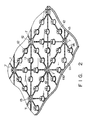
- Fig. 2 is a view showing an arrangement of the floor base member 1 according to the first embodiment.
- a plurality of floor base members 1 are arranged on a foundation floor surface of a room.
- connecting support members 12 of the adjacent floor base members 1 are brought into contact to constitute truncated cones.
- the adjacent connecting support members 12 are connected by the base joint members 7.
- Four adjacent connecting support members 13 at the adjacent corners of the four floor base members 1 are combined to constitute a truncated cone which is then connected by the base joint member 7. Therefore, the adjacent floor base members 1 can be connected to each other and are firmly fixed to each other. Therefore, when the floor panel members 2 are intalled as the entire upper surface of the floor base members 1, stability of the floor panel members 2 can be assured.
- Figs. 3A to 3C, Figs. 4A and 4B, Figs. 5A and 5B, and Fig. 6 are views respectively showing modifications of the coupling support member and the base joint member of the first embodiment.
- the connecting support member 13 extending at each corner of the floor base member 1 may be a 1/4 piece (one of pieces 33a to 33d) shown in Fig. 3A or a 1/4 piece (one of pieces 34a to 34d) in Fig. 3B.
- the connecting support member 12 extending at the edge except for any corner of the floor base member 1 comprises a 1/2 piece (one of pieces 32a and 32b), as shown in Fig. 3C.
- base joint members e.g., a rectangular ring
- the connecting support member 13 extending at any corner of the floor base member 1 may be a 1/4 piece (one of pieces 40a to 40d) obtained by dividing a member 40 (Fig. 4A) into quarters.
- the base joint member comprises a member 42 having a shape to fit with a cross guide groove 41 formed on the upper surface of the member 40, as shown in Fig. 4A.
- the connecting support member 12 extending at the edge except for any corner may be a 1/2 piece (one of pieces 43a and 43b) of a member 43 shown in Fig. 4B.
- the base joint member comprises a member 44 having a shape to fit in a guide groove 45 formed on the upper surface of the member 43, as shown in Fig. 4B.
- the connecting support member 13 extending at any corner comprises a 1/4 piece (one of pieces 50a to 50d) obtained by dividing a member 50 (Fig. 5A) into quarters.
- the base joint member comprises a member 52 having a shape to fit in a ring-like groove 51 formed on the upper surface of the member 50.
- the member 52 has a central recess and a ring-like peripheral projection fitted in the ring-like groove 51.
- a 1/2 piece of the member 50 shown in Fig. 5A may be used as the connecting support member 12 extending at the edge except for the corner. In this case, when the two connecting support members 12 are combined, the member 50 is constituted.
- the member 52 is fitted in the ring-like groove 51 to connect adjacent connecting support members 12.
- Fig. 6 shows a modification as a combination of a joint portion 60 and a connecting support member 61.
- the joint portion 60 formed at part of the peripheral portion of the floor base member 1 corresponds to the base joint members
- the connecting support member 61 has a recess at its center. The recess is engaged with the corresponding joint portion 60 of the adjacent floor base member 1 to connect the adjacent floor base members 1.
- Fig. 7 shows a modification of the floor panel member according to the first embodiment.
- This floor panel member has nine pieces 70a to 70i connected through thin adhesive sheets, and the adhered nine pieces constitute a standard member. Any of the pieces 70a to 70i can be removed as needed.
- floor panel members as a combination obtained by using a plurality of pieces having the circular openings 21 and the rectangular notches 22, a panel shape can be arbitrarily changed.
- Fig. 9 is a plan view showing a modification of the above structure of the upper surface of the fundamental support member 11.
- Vertical grooves 11b are formed on the circumferential surface of the fundamental support members 11 to support both ends of a vertical separator member 9.
- the vertical separator member 9 comprises a plate member for partitioning the horizontal space on the surface of the floor base 1.
- a plurality (e.g., four) of recesses 90a to 90d are formed on the upper surface of the fundamental support member 11.
- a plurality of (e.g., four) projections 100 which respectively engage with the recesses 90a to 90d are formed on the lower surface of the floor panel member 2, as shown in Fig. 10.
- Damping members 23 are formed around the projections 100 on the lower surface of the floor panel member 2.
- Fig. 11 is a view showing the lower surface (i.e., a surface which is brought into contact with the foundation floor surface of the room) of the floor base member 1.
- a plate-like rubber member 16 having a three-dimensional pattern for preventing slippage on its surface is adhered to the lower surface of the floor base member 1.
- Figs. 12A to 14C are views showing the third embodiment of the present invention.
- slit-like vertical grooves 11b, 12b, and 13b are respectively formed on the circumferential wall surfaces of fundamental support members 11 and connecting support members 12 and 13, all of which extend on a floor base member 1.
- the vertical grooves 11b, 12b, and 13b are used to support both ends of vertical separator members 9 bridged between the adjacent support members 11 to 13 (Fig. 12B).
- Each vertical separator member 9 comprises a plate member to partition a horizontal space on the surface of the floor base member 1.
- a horizontal separator 8 is prepared to partition the vertical space.
- Each horizontal separator member 8 comprises a plate member and is normally engaged with four adjacent fundamental support members 11 formed on the surface of the floor base member 1 to partition the vertical space.
- Four holes each having a diameter slightly larger than the hole at the center of the frustoconical support member 11 are formed at four corners of the horizontal separator member 8.
- the horizontal separator member 8 is engaged with the adjacent fundamental support member 11 and the connecting support members 12 and 13 to partition the vertical space.
- Figs. 14A to 14C are views showing box-like separator members 80 to 82 as modifications of the vertical or horizontal separator member.
- the box-like separator members 80 to 82 are made of a metal such as aluminum.
- the box-like separators 80 to 82 have four corners 80a to 80d which are brought into contact with the peripheral surfaces of the four adjacent fundamental support members 11 so as to conform to the circumferential surfaces.
- the box-like separator member 80 shown in Fig. 14A does not have side surfaces corresponding to those of the vertical separator member 9 and is used as a horizontal separator member 8.
- Figs. 15A to 16 are views showing the fourth embodiment.
- a floor panel member 2 comprises a foamed metal base member 231, a cover member 232 consisting of a punching metal and formed on the upper surface of the base member 231, and a cover member 233 consisting of a punching metal and formed on the lower surface of the base member 231.
- Figs. 17A and 17B are views of the fifth embodiment.
- a fundamental support member 11 and connecting support members 12 and 13 extend on a floor base member 1 to support a floor panel member 2.
- V-grooves 14a are formed on the surface of the floor base member 1 by a line connecting middle points of the long sides of the floor base member 1 and diagonals of rectangles (squares) of the rectangular floor base member 1 so as to connect between the support members 11 to 13.
- Grooves 14b are formed to surround a 1/2 bottom arc of each fundamental support member 11 and the entire bottom arc of each connecting support member 12.
- a groove 14c is also formed to surround the entire bottom arc of each connecting support member 13 extending at any corner.
- the grooves 14a to 14c serve as guide grooves for discharging leaking water.
- Guide holes 15 for discharging the leaking water to the foundation floor surface are formed in the V-grooves 14a at predetermined intervals (Fig. 17B). With this structure, water leaking on the upper surface of the floor base member 1 is guided to the guide holes 15 through the grooves 14a to 14c, thereby effectively discharging water to the foundation floor surface. Therefore, the cables and various devices arranged between the floor base member 1 and the floor panel member 2 can be protected from any trouble caused by water leakage, thereby maintaining a stable system operation.
- wiring patterns P for detecting water leakage are formed at both sides of the V-groove 14a to constitute a water leakage sensor.
- the wiring patterns P are connected to a sensor circuit 170 arranged at a predetermined position of the floor base member 1.
- the sensor circuit 170 When leaking water is brought into contact with the wiring patterns P, e.g., when a circuit consisting of the leaking water and the wiring patterns P is formed, the sensor circuit 170 outputs a detection signal to drive, e.g., a buzzer unit.
- the wiring patterns P may be formed near other grooves 14b and 14c in addition to the portions adjacent to the V-groove 14a.
- Figs. 18A to 19 are views showing the sixth embodiment of the present invention.
- a fan unit F is mounted utilizing a circular opening 21 of a floor panel member 2 to constitute a ventilation system.
- the fan unit F is held by a device support mechanism 180 provided to the lower surface of a floor panel member 2.
- a vent port 181 is formed on the upper surface of the floor panel member 2.
- a ventilation duct is formed between the floor base member 1 and the floor panel member 2.
- the ventilation duct, the fan unit F, and the vent port 181 constitute a ventilation system (or air-conditioning system).
- a basket B corresponding to a device support mechanism 180 is formed on the lower surface of a floor panel member 2 by utilizing a circular opening 21.
- an insecticide or desiccant may be stored in the basket B to kill harmful insects entering the space between the floor base member 1 and the floor panel member 2 or remove humidity. Therefore, a good environment can be maintained for the cables and various devices arranged between the floor base member 1 and the floor panel member 2.
- Figs. 20 to 23 are views showing the seventh embodiment.
- floor base members 1, floor panel members 2, and floor carpets 3 are sequentially installed on a foundation floor surface of a room 190 to constitute an upper floor surface of the room 190.
- Boarder fundamental members 4 are installed on the foundation floor surface of the room 190 at this location (i.e., a boarder area).
- Each boarder fundamental member 4 comprises a strip member having a rectangular wave shape and a predetermined width.
- a plurality of boarder fundamental members 4 are combined in accordance with the size of the boarder area and are installed in the boarder area. In this case, as shown in Fig.
- the boarder columnar joint 4a is fitted in the joint mounting groove 41 arranged in each boarder fundamental member 4, so that the boarder fundamental members 4 are integrally formed.
- a boarder floor panel 5 is placed on the upper surface of each boarder fundamental member 4.
- the boarder floor panel 5 has longitudinal grooves which can be cut to have a predetermined width in accordance with the size of the boarder area.
- a boarder floor carpet 6 similar to the floor carpet 3 is placed on the upper surface of the boarder floor panel 5.
- the boarder fundamental member 4 may have a strip member having a corrugated shape, as shown in Fig. 21A. As shown in Fig. 21B, a joint mounting groove 41 and semispherical openings 42 for wiring may be formed in the corrugated boarder fundamental member 4. When the signal or power cables are installed on the foundation floor surface of the room 190, each cable extends through the opening 42 as needed.
- the boarder fundamental member 4 may have a comb-like shape. When a plurality of comb-like boarder fundamental members 4a and 4b are combined, an inter-digital pattern is formed, as shown in Fig. 22B.
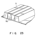
- the boarder floor panel 5 has longitudinal grooves 5a so as to be cut to have a predetermined width, as shown in Fig. 23. Therefore, the boarder floor panel 5 is cut at a predetermined longitudinal groove 5a in accordance with the size of the boarder area, thereby forming a boarder floor panel 5 having an optimal size.
- the floor surface of the room can be formed together with the members 1 to 3 in the boarder area where the members 1 to 3 of the room cannot be installed.
Abstract
Description
- The present invention relates to an interior panel unit for permitting an arrangement of cables and devices on a room floor, the panel being used in an office or computer room to arrange an office-automation system.
- A conventional interior panel unit is available to realize an office-automation system by arranging power cables, signal cables, and various types of equipment on a room floor in an office or computer room, as described in U.S.P. Nos. 4,593,499 and 4,631 879.
- More specifically, a given unit has blocks having shapes to be engaged with each other at a peripheral portion of a rectangular floor base installed on a foundation floor surface of a room, and blocks on each floor base are engaged with and coupled to each other to form each floor base on the foundation floor surface.
- In another unit, a plurality of columnar members are mounted on a lower floor base installed on a foundation floor surface, and an upper floor base is supported by the columnar members with a gap corresponding to the height of each columnar member from the foundation floor surface.
- However, in the former unit, an operation for coupling the blocks of the adjacent floor bases is required. This operation is cumbersome and time-consuming. Therefore, much labor is required to install the floor bases on the entire surface of the foundation floor base of the room. In addition, when each block is designed each that it fits tight into another, thereby to form a strong unit. Much labor is also required to form such a unit. Consequently, it takes much time to assemble and install the interior panel unit. When the blocks are loosely coupled to each other, the installation can be facilitated. However, the upper floor consisting of floor bases does not have a sufficiently flat surface or adequate stability.
- The latter unit has a structure wherein the lower floor base is installed on the foundation floor surface of the room and the upper floor base is supported and fixed through the plurality of columnar members. The adjacent lower floor bases are not coupled to each other. For this reason, the lower floor bases are not integrally coupled. Therefore, when the upper floor base is supported and fixed, stability and flatness of the upper floor surface consisting of the upper floor bases are degraded.
- It is an object of the present invention to provide an interior panel unit for permitting an arrangement of cables and devices on a room floor, wherein an installation operation can be simplified, operability can be improved, and stability and flatness of an upper floor surface upon installation can be improved.
- In order to achieve the above object of the present invention, there is provided an interior panel unit for creating an office-automation system by arranging power and signal cables and devices on a room floor, comprising: floor base member to be installed on a foundation floor of a room; a plurality of fundamental support members fixed to upper surface of each of the floor base members, and having upper surfaces located at the same height from the upper surface of each floor base member; a plurality of connecting support members fixed to peripheral portions of each floor base member, and having upper surfaces located the same height as those of the fundamental support members; base joint members for connecting the connecting support members arranged on a plurality of floor base members in a state wherein the floor base members are installed on the same surface; and floor panel members brought into contact with the upper surfaces of the plurality of fundamental support members and the upper surfaces of the connecting support members to form a surface of the room floor and cooperating with the floor base members to define an internal space for installing cables and devices therein.
- This invention can be more fully understood from the following detailed description when taken in conjunction with the accompanying drawings, in which:
- Fig. 1 is an exploded perspective view showing an overall arrangement of an interior panel unit according to the present invention;
- Fig. 2 is a perspective view showing a structure of a floor base member according to a first embodiment of the present invention;
- Figs. 3A to 3C are perspective views respectively showing modifications of a connecting support member according to the first embodiment of the present invention;
- Figs. 4A, 4B, 5A, 5B, and 6 are perspective views respectively showing modifications of a base joint member according to the first embodiment of the present invention;
- Fig. 7 is a perspective view showing a modification of a floor panel member according to the first embodiment of the present invention;
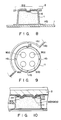
- Figs. 8 and 10 are sectional views showing a fundamental support member according to a second embodiment of the present invention;
- Fig. 9 is a plan view showing the fundamental support member according to the second embodiment of the present invention;
- Fig. 11 is a plan view showing a floor base member according to the second embodiment of the present invention;
- Fig. 12A is a perspective view showing an arrangement of a vertical separator member according to a third embodiment of the present invention;
- Fig. 12B is a sectional view showing an arrangement of the vertical separator member according to the third embodiment of the present invention;
- Fig. 13A is a perspective view showing an arrangement of a horizontal separator member according to the third embodiment of the present invention;
- Fig. 13B is a sectional view showing an arrangement of the vertical separator member according to the third embodiment of the present invention;
- Figs. 14A to 14C are perspective views respectively showing arrangements of the vertical or horizontal separator members according to the third embodiment of the present invention;
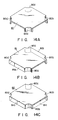
- Fig. 15A is a perspective view showing a floor panel member according to a fourth embodiment of the present invention;
- Fig. 15B is a plan view showing an arrangement of the floor panel member according to the fourth embodiment of the present invention;
- Fig. 16 is a sectional view showing a modification of the floor panel member according to the fourth embodiment of the present invention;
- Fig. 17A is a plan view showing an arrangement of a floor base member according to a fifth embodiment of the present invention;
- Fig. 17B is a sectional view showing an arrangement of the floor base member according to the fifth embodiment of the present invention;
- Fig. 18A is a perspective view showing an arrangement of a floor panel member with a fan unit according to a sixth embodiment of the present invention;
- Fig. 18B is a sectional view showing an arrangement of the floor panel member with the fan unit according to the sixth embodiment of the present invention;
- Fig. 19 is a sectional view showing an arrangement of a floor panel member with a basket according to the sixth embodiment of the present invention;
- Fig. 20 is a plan view showing a layout of a boarder fundamental member according to a seventh embodiment of the present invention;
- Figs. 21A and 21B are perspective views showing arrangements of the border fundamental members according to the seventh embodiment of the present invention;
- Fig. 22A is a perspective view showing a modification of the boarder fundamental member according to the seventh embodiment of the present invention;
- Fig. 22B is a plan view showing the member shown in Fig. 22A; and
- Fig. 23 is a perspective view showing an arrangement of a boarder floor panel member according to the seventh embodiment of the present invention.
- Preferred embodiments of the present invention will be described with reference to the accompanying drawings.
- Fig. 1 is a view showing an overall structure of an interior panel unit according to the present invention. The unit comprises
floor base members 1 installed on afoundation floor surface 4 which defines a space of an office or computer room. Eachfloor base member 1 consists of a flexible synthetic resin (e.g., polypropylene) as a base material and comprises a rectangular plate having a ratio of a long side to a short side of 2 : 1 (e.g., 1 m : 500 mm). - Fundamental support members (fundamental columns) 11 for supporting a
floor panel member 2 are located on the surface of thefloor base member 1 except for the edge at predetermined intervals. Connecting support members (connecting columns) 12 are located at the edge except for corners of the upper surface of thefloor base member 1. Connectingsupport members 13 are located at the corners of the upper surface of thefloor base member 1. Thesupport members 11 to 13 consist of a fire-retardant material such as foamed concrete and have the same height. It should be noted that 10fundamental support members support members 12 extending at the edge except for the corners, and four connectingsupport members 13 at the four corners are formed on eachfloor base member 1. - Each
fundamental support member 11 comprises a truncated cone and has a recess 11a at almost the center of the upper surface which is to contact the surface of thefloor panel member 2. The recess 11a serves to prevent lateral shift of thefloor panel member 2. Each connectingsupport member 12 extending at the edge except for the corners consists of a half piece which is obtained by cutting a truncated cone corresponding to thefundamental support member 11 in the vertical direction (i.e., a direction perpendicular to the surface of the floor base member 1). Each connectingsupport member 13 extending at each corner of eachfloor base member 1 comprises a 1/4 piece obtained by cutting the conical member corresponding to thefundamental support member 11 in the vertical directions. A slit-likevertical groove 11b is formed in the circumferential wall of each of thesupport members 11 to 13. Thevertical grooves 11b are formed to support both ends of avertical separator member 9 bridged between the adjacent ones of thesupport members 11 to 13. Thevertical separator member 9 is a plate member for partitioning the horizontal space on the surface of thefloor base member 1. - V-shaped grooves (to be referred to as V-grooves hereinafter) 14a are formed in the surface of the
floor base member 1 to connect the adjacent ones of thesupport members 11 to 13 with lines on a line obtained by connecting the middle points of the long sides and diagonal lines within each one of rectangles (squares) obtained by dividing the rectangular area into halves.Grooves 14b are formed to surround the 1/2 bottom arc of thefundamental support member 11 and the entire bottom arc of the connectingsupport member 12 extending at the edge, and a groove 14c is also formed to surround the entire bottom arc of the connectingsupport member 13 extending at each corner. The grooves 14a to 14c serve as guide grooves for discharging leaking water. Guide holes 15 are formed in the V-grooves 14a at predetermined intervals to discharge water to the foundation floor surface. - The
floor panel member 2 is a member supported by thesupport members 11 to 13 of thefloor base member 1 to constitute an upper floor surface of the room. Eachfloor panel member 2 consists of a rectangular (square) plate member having anarea 1/2 that of eachfloor base member 1. More specifically, each side of the square of thefloor panel member 2 is, e.g., 500 mm. Acircular opening 21 is formed at almost the center of eachfloor panel member 2.Rectangular notches 22 are formed at opposite sides of eachfloor panel member 2. Thecircular opening 21 is used to set various devices such as a circularblank piece 211, afloor outlet 212, anaddress panel 213, and a light-accumulating panel (nighttime marker lamp) 214. Eachrectangular notch 22 is used to install various devices such as a rectangularblank piece 221, afloor outlet 222, and a partition joint part (partition connecting piece) 223. A projection is formed on the lower surface (i.e., a surface which is brought into contact with thesupport members 11 to 13) of thefloor panel member 2 to engage with the recess 11a formed on almost the center of the upper surface of the correspondingfundamental support member 11. - A
floor carpet 3 is installed on the surface of thefloor panel member 2. Thefloor carpet 3 consists of a fire-retardant material and has a size corresponding to the area of thefloor panel member 2. Thefloor carpet 3 has an arbitrary shape in accordance with thecircular opening 21 andrectangular notches 22 formed in thefloor panel member 2. - When the plurality of
floor base members 1 are arranged on the foundation floor surface of the room, the adjacent connectingsupport members 13 extending at the four corners are connected to each other by basejoint members 7. Each basejoint member 7 is engaged with a truncated cone obtained by combining four adjacent connectingsupport members 13 to connect these connectingsupport members 13. The adjacent connectingsupport members 12 extending at edges of the adjacentfloor base members 1 are connected by the corresponding basejoint members 7. The plurality of adjacentfloor base members 1 are connected by the basejoint members 7. -
Horizontal separator members 8 are prepared to partition the space defined by thefloor panel members 2 and thefloor base members 1 so as to partition the space vertically. Eachhorizontal separator member 8 comprises a plate member which is engaged with four adjacentfundamental support members 11 extending on the surface of thefloor base member 1 to partition the vertical space. Four holes each having a diameter slightly larger than that of the hole almost at the center of thefrustoconical support member 11 are formed on thevertical separator member 8 so that thevertical separator member 8 is supported almost at the centers of the correspondingfundamental support members 11. By utilizing the space partitioned by thesevertical separator members 8,network devices 10 connected to, e.g., signal and power cables can be three-dimensionally arranged between thefloor panel members 2 and thefloor base members 1. - When the
floor base members 1 and thefloor panel members 2 are installed to form an upper floor surface of a room, there are always corners where thefloor base members 1 and thefloor panel members 2 cannot be installed. Boarderfundamental members 4 are installed on the foundation floor surface of the room at these corners. Each boarderfundamental member 4 comprises a strip member having a rectangular wave shape and a predetermined width. A plurality of boarderfundamental members 4 are combined in accordance with the size of a boarder area where thefloor base members 1 and thefloor panel members 2 cannot be installed. The plurality of boarderfundamental members 4 are installed in this boarder area. In this case, a boarder support joint 4a is fitted in a joint mountinggroove 41 formed in each boarderfundamental member 4, so that the boarderfundamental members 4 can be integrally formed. Aboarder floor panel 5 is installed on the upper surface of each borderfundamental member 4. Theboarder floor panel 5 has longitudinal grooves so that it can be cut to obtain a desirable width in accordance with the boarder area. In addition, aboarder floor carpet 6 similar to thefloor carpet 3 is installed on theboarder floor panel 5. - The structures of the respective members of the interior panel unit will be described in detail according to the first to seventh embodiments.
- Fig. 2 is a view showing an arrangement of the
floor base member 1 according to the first embodiment. A plurality offloor base members 1 are arranged on a foundation floor surface of a room. In this case, connectingsupport members 12 of the adjacentfloor base members 1 are brought into contact to constitute truncated cones. The adjacent connectingsupport members 12 are connected by the basejoint members 7. Four adjacent connectingsupport members 13 at the adjacent corners of the fourfloor base members 1 are combined to constitute a truncated cone which is then connected by the basejoint member 7. Therefore, the adjacentfloor base members 1 can be connected to each other and are firmly fixed to each other. Therefore, when thefloor panel members 2 are intalled as the entire upper surface of thefloor base members 1, stability of thefloor panel members 2 can be assured. - Figs. 3A to 3C, Figs. 4A and 4B, Figs. 5A and 5B, and Fig. 6 are views respectively showing modifications of the coupling support member and the base joint member of the first embodiment. The connecting
support member 13 extending at each corner of thefloor base member 1 may be a 1/4 piece (one ofpieces 33a to 33d) shown in Fig. 3A or a 1/4 piece (one of pieces 34a to 34d) in Fig. 3B. The connectingsupport member 12 extending at the edge except for any corner of thefloor base member 1 comprises a 1/2 piece (one ofpieces 32a and 32b), as shown in Fig. 3C. When these connectingsupport members support members - The connecting
support member 13 extending at any corner of thefloor base member 1 may be a 1/4 piece (one ofpieces 40a to 40d) obtained by dividing a member 40 (Fig. 4A) into quarters. In this case, the base joint member comprises amember 42 having a shape to fit with across guide groove 41 formed on the upper surface of themember 40, as shown in Fig. 4A. The connectingsupport member 12 extending at the edge except for any corner may be a 1/2 piece (one ofpieces member 43 shown in Fig. 4B. In this case, the base joint member comprises amember 44 having a shape to fit in aguide groove 45 formed on the upper surface of themember 43, as shown in Fig. 4B. - According to still another modification, the connecting
support member 13 extending at any corner comprises a 1/4 piece (one ofpieces 50a to 50d) obtained by dividing a member 50 (Fig. 5A) into quarters. In this case, the base joint member comprises amember 52 having a shape to fit in a ring-like groove 51 formed on the upper surface of themember 50. As shown in Fig. 5B, themember 52 has a central recess and a ring-like peripheral projection fitted in the ring-like groove 51. A 1/2 piece of themember 50 shown in Fig. 5A may be used as the connectingsupport member 12 extending at the edge except for the corner. In this case, when the two connectingsupport members 12 are combined, themember 50 is constituted. Themember 52 is fitted in the ring-like groove 51 to connect adjacent connectingsupport members 12. - Fig. 6 shows a modification as a combination of a
joint portion 60 and a connectingsupport member 61. Thejoint portion 60 formed at part of the peripheral portion of thefloor base member 1 corresponds to the base joint members The connectingsupport member 61 has a recess at its center. The recess is engaged with the correspondingjoint portion 60 of the adjacentfloor base member 1 to connect the adjacentfloor base members 1. - Fig. 7 shows a modification of the floor panel member according to the first embodiment. This floor panel member has nine pieces 70a to 70i connected through thin adhesive sheets, and the adhered nine pieces constitute a standard member. Any of the pieces 70a to 70i can be removed as needed. By using floor panel members as a combination obtained by using a plurality of pieces having the
circular openings 21 and therectangular notches 22, a panel shape can be arbitrarily changed. - Figs. 8 to 11 are views showing the second embodiment.
- As shown in Fig. 8, a
projection 21a engaged with a recess 11a formed on almost the center of the upper surface of afundamental support member 11 is formed on the lower surface of afloor panel member 2. The recess 11a serves to prevent lateral shift. In addition, damping members (cushion members consisting of, e.g., rubber) which are brought into tight contact with the upper surface of thefundamental support member 11 are formed at four peripheral portions of theprojection 21a on the lower surface of thefloor panel member 2. With this structure, when thefloor panel member 2 is placed on the upper surfaces of thefundamental support member 11 and connectingsupport members member 2 can be prevented, and thefloor panel member 2 can be accurately supported. - Fig. 9 is a plan view showing a modification of the above structure of the upper surface of the
fundamental support member 11.Vertical grooves 11b are formed on the circumferential surface of thefundamental support members 11 to support both ends of avertical separator member 9. Thevertical separator member 9 comprises a plate member for partitioning the horizontal space on the surface of thefloor base 1. A plurality (e.g., four) of recesses 90a to 90d are formed on the upper surface of thefundamental support member 11. A plurality of (e.g., four) projections 100 which respectively engage with the recesses 90a to 90d are formed on the lower surface of thefloor panel member 2, as shown in Fig. 10. Dampingmembers 23 are formed around the projections 100 on the lower surface of thefloor panel member 2. - Fig. 11 is a view showing the lower surface (i.e., a surface which is brought into contact with the foundation floor surface of the room) of the
floor base member 1. A plate-like rubber member 16 having a three-dimensional pattern for preventing slippage on its surface is adhered to the lower surface of thefloor base member 1. When thefloor base member 1 is installed on the fundamental floor surface of the room, unstable movement of thefloor base member 1 can be prevented. - Figs. 12A to 14C are views showing the third embodiment of the present invention.
- As shown in Fig. 12A, slit-like
vertical grooves fundamental support members 11 and connectingsupport members floor base member 1. Thevertical grooves vertical separator members 9 bridged between theadjacent support members 11 to 13 (Fig. 12B). Eachvertical separator member 9 comprises a plate member to partition a horizontal space on the surface of thefloor base member 1. By using thesevertical separator members 9, a path of cables such as signal and power cables and a ventilation path are formed in the space defined between thefloor base members 1 and thefloor panel members 2. - As shown in Fig. 13A, in the space defined by the
floor panel member 2 and thefloor base member 1, ahorizontal separator 8 is prepared to partition the vertical space. Eachhorizontal separator member 8 comprises a plate member and is normally engaged with four adjacentfundamental support members 11 formed on the surface of thefloor base member 1 to partition the vertical space. Four holes each having a diameter slightly larger than the hole at the center of thefrustoconical support member 11 are formed at four corners of thehorizontal separator member 8. Thehorizontal separator member 8 is engaged with the adjacentfundamental support member 11 and the connectingsupport members - By using this
horizontal separator member 8, the spaces above and below theflow base member 1 are assured to three-dimensionally arrange, e.g., signal and power cables, as shown in Fig. 13B. - Figs. 14A to 14C are views showing box-
like separator members 80 to 82 as modifications of the vertical or horizontal separator member. The box-like separator members 80 to 82 are made of a metal such as aluminum. The box-like separators 80 to 82 have four corners 80a to 80d which are brought into contact with the peripheral surfaces of the four adjacentfundamental support members 11 so as to conform to the circumferential surfaces. The box-like separator member 80 shown in Fig. 14A does not have side surfaces corresponding to those of thevertical separator member 9 and is used as ahorizontal separator member 8. The box-like separator members 81 and 82 shown in Figs. 14B and 14C have side surfaces 81a, 81b, and 81c corresponding to those of thevertical separator member 9 and can partition the space by means of the side surfaces. When the box-like separator members 80 to 82 are used as thehorizontal separator members 8, their height must be set to be almost about 1/2 that of each of thefundamental support member 11 and the connectingsupport members floor base member 1 and thefloor panel member 2 can be vertically partitioned. - Figs. 15A to 16 are views showing the fourth embodiment.
- As shown in Fig. 15A (15B), a
floor panel member 2 comprises a foamedmetal base member 231, acover member 232 consisting of a punching metal and formed on the upper surface of thebase member 231, and acover member 233 consisting of a punching metal and formed on the lower surface of thebase member 231. With this structure, a floor reinforced by thecover members - As shown in Fig. 16, the
floor panel member 2 comprises abase member 241 of a honeycomb structure consisting of a foamed metal, a ceramic, a metal plate of aluminum or the like, or paper. Acover member 242 consisting of a punching metal is formed on the upper surface of thebase member 241. A reinforcingmember 243 consisting of carbon fibers is formed on the lower surface of thebase member 241. Afloor carpet 3 is installed on the upper surface of thecover member 242. With this structure, the same ventilation property as that in Fig. 15A can be obtained, and the floor is reinforced with thecover member 242 and the reinforcingmember 243. - Figs. 17A and 17B are views of the fifth embodiment.
- As shown in Fig. 17A, a
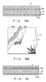
fundamental support member 11 and connectingsupport members floor base member 1 to support afloor panel member 2. V-grooves 14a are formed on the surface of thefloor base member 1 by a line connecting middle points of the long sides of thefloor base member 1 and diagonals of rectangles (squares) of the rectangularfloor base member 1 so as to connect between thesupport members 11 to 13.Grooves 14b are formed to surround a 1/2 bottom arc of eachfundamental support member 11 and the entire bottom arc of each connectingsupport member 12. A groove 14c is also formed to surround the entire bottom arc of each connectingsupport member 13 extending at any corner. The grooves 14a to 14c serve as guide grooves for discharging leaking water. Guide holes 15 for discharging the leaking water to the foundation floor surface are formed in the V-grooves 14a at predetermined intervals (Fig. 17B). With this structure, water leaking on the upper surface of thefloor base member 1 is guided to the guide holes 15 through the grooves 14a to 14c, thereby effectively discharging water to the foundation floor surface. Therefore, the cables and various devices arranged between thefloor base member 1 and thefloor panel member 2 can be protected from any trouble caused by water leakage, thereby maintaining a stable system operation. - As shown in Fig. 17B, wiring patterns P for detecting water leakage are formed at both sides of the V-groove 14a to constitute a water leakage sensor. The wiring patterns P are connected to a
sensor circuit 170 arranged at a predetermined position of thefloor base member 1. When leaking water is brought into contact with the wiring patterns P, e.g., when a circuit consisting of the leaking water and the wiring patterns P is formed, thesensor circuit 170 outputs a detection signal to drive, e.g., a buzzer unit. The wiring patterns P may be formed nearother grooves 14b and 14c in addition to the portions adjacent to the V-groove 14a. With this arrangement, when water leakage occurs on thefloor base member 1, it can be detected and alarmed. Therefore, the leaking water can be immediately removed, and the cables and various devices arranged between thefloor base member 1 and the floor panel member can be protected from any trouble caused by water leakage. - Figs. 18A to 19 are views showing the sixth embodiment of the present invention.
- As shown in Figs. 18A and 18B, a fan unit F is mounted utilizing a
circular opening 21 of afloor panel member 2 to constitute a ventilation system. The fan unit F is held by adevice support mechanism 180 provided to the lower surface of afloor panel member 2. Avent port 181 is formed on the upper surface of thefloor panel member 2. By utilizing thevertical separator members 9, a ventilation duct is formed between thefloor base member 1 and thefloor panel member 2. The ventilation duct, the fan unit F, and thevent port 181 constitute a ventilation system (or air-conditioning system). - As shown in Fig. 19, a basket B corresponding to a
device support mechanism 180 is formed on the lower surface of afloor panel member 2 by utilizing acircular opening 21. For example, an insecticide or desiccant may be stored in the basket B to kill harmful insects entering the space between thefloor base member 1 and thefloor panel member 2 or remove humidity. Therefore, a good environment can be maintained for the cables and various devices arranged between thefloor base member 1 and thefloor panel member 2. - Figs. 20 to 23 are views showing the seventh embodiment.
- As shown in Fig. 20,
floor base members 1,floor panel members 2, andfloor carpets 3 are sequentially installed on a foundation floor surface of aroom 190 to constitute an upper floor surface of theroom 190. There is acorner 191 of theroom 190 where themembers 1 to 3 cannot be installed. Boarderfundamental members 4 are installed on the foundation floor surface of theroom 190 at this location (i.e., a boarder area). Each boarderfundamental member 4 comprises a strip member having a rectangular wave shape and a predetermined width. A plurality of boarderfundamental members 4 are combined in accordance with the size of the boarder area and are installed in the boarder area. In this case, as shown in Fig. 1, the boarder columnar joint 4a is fitted in the joint mountinggroove 41 arranged in each boarderfundamental member 4, so that the boarderfundamental members 4 are integrally formed. Aboarder floor panel 5 is placed on the upper surface of each boarderfundamental member 4. Theboarder floor panel 5 has longitudinal grooves which can be cut to have a predetermined width in accordance with the size of the boarder area. In addition, aboarder floor carpet 6 similar to thefloor carpet 3 is placed on the upper surface of theboarder floor panel 5. - The boarder
fundamental member 4 may have a strip member having a corrugated shape, as shown in Fig. 21A. As shown in Fig. 21B, a joint mountinggroove 41 andsemispherical openings 42 for wiring may be formed in the corrugated boarderfundamental member 4. When the signal or power cables are installed on the foundation floor surface of theroom 190, each cable extends through theopening 42 as needed. In addition, as shown in Fig. 22A, the boarderfundamental member 4 may have a comb-like shape. When a plurality of comb-like boarderfundamental members - The
boarder floor panel 5 haslongitudinal grooves 5a so as to be cut to have a predetermined width, as shown in Fig. 23. Therefore, theboarder floor panel 5 is cut at a predeterminedlongitudinal groove 5a in accordance with the size of the boarder area, thereby forming aboarder floor panel 5 having an optimal size. - By using the boarder
fundamental members 4, theboarder floor panels 5, and theboarder floor carpets 6, the floor surface of the room can be formed together with themembers 1 to 3 in the boarder area where themembers 1 to 3 of the room cannot be installed.
Claims (18)
characterized by comprising:
a plurality of fundamental support members (11) fixed to an upper surface of each of said floor base member (1), and having upper surfaces located at the same height from said upper surface of each floor base member (1);
a plurality of connecting support members (12, 13) fixed to peripheral portions of each floor base member (1), and having upper surfaces located the same height as those of said fundamental support members (11);
base joint members (7) for connecting said connecting support members (12, 13) arranged on a plurality of said floor base members (1) in a state wherein the floor base members are installed on the same surface; and
floor panel members (2) brought into contact with said upper surfaces of said plurality of fundamental support members (11) and said upper surfaces of said connecting support members (12, 13) to form a surface of the room floor and cooperating with said floor base members (1) to define an internal space for installing cables and devices therein.
a device mounting hole (21) formed in said floor panel member (2); and
a device support mechanism (180, B), formed on said lower surface of said floor panel member (2), for mounting various devices at a position corresponding to said device mounting hole (21).
characterized by comprising:
a plurality of fundamental support members (11) fixed to an upper surface of each of said floor base member (1), and having upper surfaces located at the same height from said upper surface of each floor base member (1);
a plurality of connecting support members (12, 13) fixed to peripheral portions of each floor base member (1), and having upper surfaces located the same height as those of said fundamental support members (11);
vertical grooves (11b) formed on a side surface of each of said plurality of fundamental support members (11) in a direction perpendicular to said floor base member (1); and
a plate-like vertical separator member (9, 80 - 82), both ends of which are fitted in and supported by said vertical grooves (11) to partition a horizontal space on said surface of said floor space member (1).
each vertical groove (12b, 13b) formed on a side surface of each of said plurality of connecting support members (12, 13) in a direction perpendicular to said floor base member (1); and
a plate-like vertical separator member (9, 80 - 82), both ends of which are fitted in and supported by said vertical grooves (12b, 13b) to partition a horizontal space on said surface of said floor space member (1).
further comprising a plate-like horizontal separator member (8, 80 - 82) having a plurality of holes fitted with adjacent fundamental support members (11) of said fundamental support members (11) in a direction perpendicular to said floor base member (1), said horizontal separator member (8, 80 - 82) being supported at a substantially middle position of said plurality of support members (11) to partition a vertical space defined by said upper surface of said floor base member (1) and said lower surface of said floor panel member (2).
characterized by comprising:
a plurality of fundamental support members (11) fixed to an upper surface of each of said floor base member (1), and having upper surfaces located at the same height from said upper surface of each floor base member (1);
a plurality of connecting support members (12, 13) fixed to peripheral portions of each floor base member (1), and having upper surfaces located the same height as those of said fundamental support members (11);
base joint members (7) for connecting said connecting support members (12, 13) arranged on a plurality of said floor base members (1) in a state wherein the floor base members are installed on the same surface;
a floor panel member (2) supported on the upper ends of said fundamental support members (11) and also the upper ends of said connecting support members (12, 13), defining the top surface of the panel unit, and providing, jointly with said floor base member (1), a space for accommodating cables and devices;
a first antiskid engaging portion (11a, 90a - 90d) formed on an upper surface of each of said plurality of fundamental support members (11); and
a second antiskid engaging portion (21a, 100), formed on a lower surface of said floor panel member and engaged with said first antiskid engaging portion (11a, 90a - 90d) when said floor panel member (2) is brought into contact with and supported by the upper surface of each of said plurality of fundamental support members (11).
a damping member (23) formed on a lower surface of said floor panel member (2) and interposed between the upper surface of each of said plurality of fundamental support members (11) and said lower surface of said floor panel member (2) when said floor panel member (2) is brought into contact with and supported by the upper surface of each of said plurality of fundamental support members (11).
floor base member (1) installed on a foundation floor surface defining a space of a room floor;
a floor panel member (2) brought into contact with and supported by an upper surface of each of said floor base member (1) to form a surface of the room floor and to cooperate with said floor base member (1) so as to define an internal space for receiving the cables and the devices;
a plurality of strip-like boarder fundamental members (4, 4a) having a wave-like shape in a widthwise direction of a boarder area and arranged in the boarder area defined by the edge of said floor base member (1) and a side wall portion of the room which continues from an edge of the room floor; and
a boarder floor panel member (5) supported by said plurality of boarder fundamental members (4, 4a) to constitute the same plane as that of an upper surface of said floor panel member in the boarder area.
Applications Claiming Priority (19)
| Application Number | Priority Date | Filing Date | Title |
|---|---|---|---|
| JP63275614A JPH02125065A (en) | 1988-10-31 | 1988-10-31 | Stay structure for floor base |
| JP63275617A JPH02125066A (en) | 1988-10-31 | 1988-10-31 | System floor |
| JP63275620A JPH02125068A (en) | 1988-10-31 | 1988-10-31 | System floor |
| JP14205588U JPH0262032U (en) | 1988-10-31 | 1988-10-31 | |
| JP275610/88 | 1988-10-31 | ||
| JP275609/88 | 1988-10-31 | ||
| JP63275609A JPH02125064A (en) | 1988-10-31 | 1988-10-31 | System floor |
| JP275620/88 | 1988-10-31 | ||
| JP63275619A JPH02125067A (en) | 1988-10-31 | 1988-10-31 | System floor |
| JP275617/88 | 1988-10-31 | ||
| JP275618/88 | 1988-10-31 | ||
| JP275614/88 | 1988-10-31 | ||
| JP275619/88 | 1988-10-31 | ||
| JP142055/88 | 1988-10-31 | ||
| JP63275618A JPH02125063A (en) | 1988-10-31 | 1988-10-31 | System floor |
| JP63275610A JPH02125061A (en) | 1988-10-31 | 1988-10-31 | Floor panel |
| AU77188/91A AU633433B2 (en) | 1988-10-31 | 1991-05-20 | Interior panel unit for permitting arrangement of cables and devices on room floor |
| AU77189/91A AU633434B2 (en) | 1988-10-31 | 1991-05-20 | Interior panel unit for permitting arrangement of cables and devices on room floor |
| AU77185/91A AU633432B2 (en) | 1988-10-31 | 1991-05-20 | Interior panel unit for permitting arrangement of cables and devices on room floor |
Related Child Applications (2)
| Application Number | Title | Priority Date | Filing Date |
|---|---|---|---|
| EP92108696A Division EP0507353A1 (en) | 1988-10-31 | 1989-10-30 | Interior panel unit for permitting arrangement of cabls and devices on room floor |
| EP92108696.3 Division-Into | 1992-05-22 |
Publications (3)
| Publication Number | Publication Date |
|---|---|
| EP0367176A2 true EP0367176A2 (en) | 1990-05-09 |
| EP0367176A3 EP0367176A3 (en) | 1991-04-10 |
| EP0367176B1 EP0367176B1 (en) | 1993-09-08 |
Family
ID=27581370
Family Applications (2)
| Application Number | Title | Priority Date | Filing Date |
|---|---|---|---|
| EP89120096A Expired - Lifetime EP0367176B1 (en) | 1988-10-31 | 1989-10-30 | Interior panel unit for permitting arrangement of cables and devices on room floor |
| EP92108696A Ceased EP0507353A1 (en) | 1988-10-31 | 1989-10-30 | Interior panel unit for permitting arrangement of cabls and devices on room floor |
Family Applications After (1)
| Application Number | Title | Priority Date | Filing Date |
|---|---|---|---|
| EP92108696A Ceased EP0507353A1 (en) | 1988-10-31 | 1989-10-30 | Interior panel unit for permitting arrangement of cabls and devices on room floor |
Country Status (5)
| Country | Link |
|---|---|
| US (1) | US5090169A (en) |
| EP (2) | EP0367176B1 (en) |
| AU (1) | AU614436B2 (en) |
| CA (1) | CA2001808C (en) |
| DE (1) | DE68908998T2 (en) |
Cited By (13)
| Publication number | Priority date | Publication date | Assignee | Title |
|---|---|---|---|---|
| EP0488312A1 (en) * | 1990-11-29 | 1992-06-03 | Kabushiki Kaisha Toshiba | Method for manufacturing system floor and floor base for system floor |
| WO1996027720A1 (en) * | 1995-03-06 | 1996-09-12 | Om Kiki Kabushiki Kaisha | An access floor system |
| EP0829594A1 (en) * | 1996-03-30 | 1998-03-18 | SICOWA Verfahrenstechnik für Baustoffe GmbH & Co. KG | Sectional false floor |
| EP1058759A1 (en) * | 1998-02-27 | 2000-12-13 | David D. Owen | Raised flooring system and method |
| US20110047907A1 (en) * | 2009-08-28 | 2011-03-03 | DZT Industries, LLC | Method and apparatus for positioning heating elements |
| US9625163B2 (en) | 2014-08-18 | 2017-04-18 | Progress Profiles Spa | Method and apparatus for positioning heating elements |
| US9719265B2 (en) | 2015-03-17 | 2017-08-01 | Progress Profiles Spa | Floor underlayment for positioning heating elements |
| US9726383B1 (en) | 2016-06-17 | 2017-08-08 | Progress Profiles S.P.A. | Support for radiant covering and floor heating elements |
| US10215423B2 (en) | 2014-08-18 | 2019-02-26 | Progress Profiles S.P.A. | Method and apparatus for positioning heating elements |
| US10859274B2 (en) | 2016-04-01 | 2020-12-08 | Progress Profiles S.P.A. | Support for radiant covering and floor heating elements |
| US10928075B1 (en) * | 2020-05-28 | 2021-02-23 | Mp Global Products, L.L.C. | Floor heating system including membranes that are configured to be joined together to house a heating cable, and membrane system including such membranes |
| USD971449S1 (en) | 2016-04-13 | 2022-11-29 | Progress Profiles S.P.A. | Floor underlayment |
| US11892176B2 (en) | 2020-05-28 | 2024-02-06 | Mp Global Products, L.L.C. | Universal membrane configured to be divided to form a base membrane and a cover membrane that is couplable to the base membrane to form an uncoupling membrane for installation between a subfloor and floor tiles |
Families Citing this family (22)
| Publication number | Priority date | Publication date | Assignee | Title |
|---|---|---|---|---|
| US5187907A (en) * | 1988-10-31 | 1993-02-23 | Kabushiki Kaisha Toshiba | Interior panel unit for permitting arrangement of cables and devices on room floor |
| US5245805A (en) * | 1988-10-31 | 1993-09-21 | Kabushiki Kaisha Toshiba | Interior panel unit for permitting arrangement of cables and devices on room floor |
| US5197244A (en) * | 1988-10-31 | 1993-03-30 | Kabushiki Kaisha Toshiba | Interior panel unit for permitting arrangement of cables and devices on room floor |
| USRE35369E (en) * | 1989-02-03 | 1996-11-05 | Guilford (Delaware) Inc. | Flooring system especially designed for facilities which house data processing equipment |
| US5392571A (en) * | 1992-04-02 | 1995-02-28 | Powerflor, Inc. | Pedestal module for raised floor and raised floor |
| AU674057B2 (en) * | 1993-04-23 | 1996-12-05 | Liebert Corporation | Modular floor sub-structure for the operational support of computer systems |
| DE4324142A1 (en) * | 1993-07-19 | 1995-02-09 | Ika Ind Kunststoff Anwendungen | Plate system |
| US5499476A (en) * | 1993-08-31 | 1996-03-19 | Interface, Inc. | Low profile raised panel flooring with metal support structure |
| US5675950A (en) * | 1994-03-25 | 1997-10-14 | Guilford (Delaware), Inc. | Metal support framework for low profile raised panel flooring |
| USRE39097E1 (en) | 1994-03-25 | 2006-05-23 | Guildford (Delaware), Inc. | Metal support framework for low profile raised panel flooring |
| US5673522A (en) * | 1994-03-25 | 1997-10-07 | Guilford, Inc. | Junction box forlow profile raised panel flooring |
| US5713168A (en) * | 1994-03-25 | 1998-02-03 | Guilford (Delaware), Inc. | Junction box for low profile raised panel flooring |
| US5828001A (en) * | 1995-02-15 | 1998-10-27 | Guilford (Delaware), Inc. | Plastic junction box with receptacle boxes |
| US6256952B1 (en) | 1998-07-27 | 2001-07-10 | Interface, Inc. | Perforated raised flooring panel |
| US6293062B1 (en) * | 1999-11-30 | 2001-09-25 | Yao-Chung Chen | Incombustible fireproof network elevated floorboard |
| US6370831B1 (en) | 2000-03-06 | 2002-04-16 | Smed International | Raised floor system and method of installing same |
| US7461482B2 (en) * | 2005-04-13 | 2008-12-09 | Cerasi Mark A | Sub-flooring assembly and method |
| US20110047898A1 (en) * | 2009-08-25 | 2011-03-03 | Hudgins David K | Building components and the buildings constructed therewith |
| USD813421S1 (en) | 2009-08-28 | 2018-03-20 | Progress Profiles Spa | Floor underlayment |
| US8955276B2 (en) * | 2012-01-25 | 2015-02-17 | Steven James Wall | Raised flooring apparatus and system |
| US20150007508A1 (en) * | 2012-02-10 | 2015-01-08 | Jarkko Valtanen | Insulation element and a system comprising the insulation element |
| AU201711371S (en) * | 2017-03-07 | 2017-05-15 | Nxt Ip Pty Ltd | Void former |
Citations (3)
| Publication number | Priority date | Publication date | Assignee | Title |
|---|---|---|---|---|
| DE3001035A1 (en) * | 1980-01-12 | 1981-07-16 | Wolfgang 2000 Hamburg Neubauer | Prefabricated sports hall floor - has covering on load distributor panels supported on grid of profile bars |
| WO1987003324A1 (en) * | 1985-11-22 | 1987-06-04 | Cablefloor (Australia) Pty. Ltd. | Flooring system |
| EP0250255A2 (en) * | 1986-06-19 | 1987-12-23 | Daiken Corporation | Floating floor |
Family Cites Families (19)
| Publication number | Priority date | Publication date | Assignee | Title |
|---|---|---|---|---|
| JPS59150854A (en) * | 1983-02-15 | 1984-08-29 | 株式会社東芝 | Precast concrete |
| JPS6043565A (en) * | 1983-08-18 | 1985-03-08 | 株式会社東芝 | Panel |
| JPS59208898A (en) * | 1983-05-13 | 1984-11-27 | 株式会社東芝 | Panel |
| DE3318694C2 (en) * | 1983-05-21 | 1985-09-12 | Franz-Josef 4434 Ochtrup Hagemann | Method for producing a floor support consisting of panels to be laid in a modular manner |
| JPS6040472A (en) * | 1983-08-12 | 1985-03-02 | 近畿電気工事株式会社 | Wiring floor material |
| JPS6043566A (en) * | 1983-08-18 | 1985-03-08 | 株式会社東芝 | Panel |
| JPS6043564A (en) * | 1983-08-18 | 1985-03-08 | 株式会社東芝 | Panel |
| JPH0623490B2 (en) * | 1983-10-31 | 1994-03-30 | 株式会社東芝 | panel |
| JPS6098044A (en) * | 1983-10-31 | 1985-06-01 | 株式会社東芝 | Panel |
| JPS6098043A (en) * | 1983-10-31 | 1985-06-01 | 株式会社東芝 | Panel |
| JPS60112954A (en) * | 1983-11-24 | 1985-06-19 | 株式会社東芝 | Panel |
| JPS60112953A (en) * | 1983-11-24 | 1985-06-19 | 株式会社東芝 | Panel |
| JPS60192051A (en) * | 1984-03-12 | 1985-09-30 | 大成建設株式会社 | Floor structure of building |
| JPS60195260A (en) * | 1984-03-15 | 1985-10-03 | 大成建設株式会社 | Floor structure |
| JPS60242252A (en) * | 1984-05-15 | 1985-12-02 | 株式会社東芝 | Panel |
| JPS6176045A (en) * | 1984-09-19 | 1986-04-18 | Matsushita Electric Ind Co Ltd | Fitting device for brush retaining cover |
| GB8510677D0 (en) * | 1985-04-26 | 1985-06-05 | Huntgreen Ltd | Floor construction |
| JPS62284854A (en) * | 1986-05-30 | 1987-12-10 | 共同カイテック株式会社 | Floor panel apparatus |
| US4905437A (en) * | 1988-04-21 | 1990-03-06 | Cablefloor (Australia) Pty. Ltd. | Flooring system and method of providing |
-
1989
- 1989-10-30 DE DE89120096T patent/DE68908998T2/en not_active Expired - Fee Related
- 1989-10-30 CA CA002001808A patent/CA2001808C/en not_active Expired - Fee Related
- 1989-10-30 EP EP89120096A patent/EP0367176B1/en not_active Expired - Lifetime
- 1989-10-30 EP EP92108696A patent/EP0507353A1/en not_active Ceased
- 1989-10-31 AU AU43933/89A patent/AU614436B2/en not_active Ceased
- 1989-10-31 US US07/429,552 patent/US5090169A/en not_active Expired - Lifetime
Patent Citations (3)
| Publication number | Priority date | Publication date | Assignee | Title |
|---|---|---|---|---|
| DE3001035A1 (en) * | 1980-01-12 | 1981-07-16 | Wolfgang 2000 Hamburg Neubauer | Prefabricated sports hall floor - has covering on load distributor panels supported on grid of profile bars |
| WO1987003324A1 (en) * | 1985-11-22 | 1987-06-04 | Cablefloor (Australia) Pty. Ltd. | Flooring system |
| EP0250255A2 (en) * | 1986-06-19 | 1987-12-23 | Daiken Corporation | Floating floor |
Cited By (34)
| Publication number | Priority date | Publication date | Assignee | Title |
|---|---|---|---|---|
| EP0488312A1 (en) * | 1990-11-29 | 1992-06-03 | Kabushiki Kaisha Toshiba | Method for manufacturing system floor and floor base for system floor |
| US5386670A (en) * | 1990-11-29 | 1995-02-07 | Kabushiki Kaisha Toshiba | Method for manufacturing system floor and floor base for system floor |
| WO1996027720A1 (en) * | 1995-03-06 | 1996-09-12 | Om Kiki Kabushiki Kaisha | An access floor system |
| US5848506A (en) * | 1995-03-06 | 1998-12-15 | Om Kiki Kabushiki Kaisha | Access floor system |
| EP0829594A1 (en) * | 1996-03-30 | 1998-03-18 | SICOWA Verfahrenstechnik für Baustoffe GmbH & Co. KG | Sectional false floor |
| EP1058759A1 (en) * | 1998-02-27 | 2000-12-13 | David D. Owen | Raised flooring system and method |
| EP1058759A4 (en) * | 1998-02-27 | 2004-05-19 | David D Owen | Raised flooring system and method |
| US10006644B2 (en) | 2009-08-28 | 2018-06-26 | Progress Profiles Spa | Method and apparatus for positioning heating elements |
| US20110047907A1 (en) * | 2009-08-28 | 2011-03-03 | DZT Industries, LLC | Method and apparatus for positioning heating elements |
| US20160033144A1 (en) * | 2009-08-28 | 2016-02-04 | Progress Profiles Spa | Method and apparatus for positioning heating elements |
| US9416979B2 (en) | 2009-08-28 | 2016-08-16 | Progress Profiles Spa | Method and apparatus for positioning heating elements |
| US9518746B2 (en) | 2009-08-28 | 2016-12-13 | Progress Profiles Spa | Method and apparatus for positioning heating elements |
| US11041638B2 (en) | 2009-08-28 | 2021-06-22 | Progress Profiles Spa | Method and apparatus for positioning heating elements |
| US9188348B2 (en) * | 2009-08-28 | 2015-11-17 | Progress Profiles Spa | Method and apparatus for positioning heating elements |
| US10739016B2 (en) | 2014-08-18 | 2020-08-11 | Progress Profiles Spa | Method and apparatus for positioning heating elements |
| US10712020B2 (en) | 2014-08-18 | 2020-07-14 | Progress Profiles Spa | Method and apparatus for positioning heating elements |
| US9625163B2 (en) | 2014-08-18 | 2017-04-18 | Progress Profiles Spa | Method and apparatus for positioning heating elements |
| US10107505B2 (en) | 2014-08-18 | 2018-10-23 | Progress Profiles Spa | Method and apparatus for positioning heating elements |
| US9777931B2 (en) | 2014-08-18 | 2017-10-03 | Progress Profiles Spa | Method and apparatus for positioning heating elements |
| US10215423B2 (en) | 2014-08-18 | 2019-02-26 | Progress Profiles S.P.A. | Method and apparatus for positioning heating elements |
| US10408469B2 (en) | 2014-08-18 | 2019-09-10 | Progress Profiles Spa | Method and apparatus for positioning heating elements |
| US9719265B2 (en) | 2015-03-17 | 2017-08-01 | Progress Profiles Spa | Floor underlayment for positioning heating elements |
| US10859274B2 (en) | 2016-04-01 | 2020-12-08 | Progress Profiles S.P.A. | Support for radiant covering and floor heating elements |
| US10502434B2 (en) | 2016-04-01 | 2019-12-10 | Progress Profiles S.P.A. | Support for radiant covering and floor heating elements |
| USD874028S1 (en) | 2016-04-13 | 2020-01-28 | Progress Profiles S.P.A. | Floor underlayment |
| USD880732S1 (en) | 2016-04-13 | 2020-04-07 | Progress Profiles S.P.A. | Floor underlayment |
| USD872901S1 (en) | 2016-04-13 | 2020-01-14 | Progress Profiles S.P.A. | Floor underlayment |
| USD841837S1 (en) | 2016-04-13 | 2019-02-26 | Progress Profiles S.P.A. | Floor underlayment |
| USD971449S1 (en) | 2016-04-13 | 2022-11-29 | Progress Profiles S.P.A. | Floor underlayment |
| US9726383B1 (en) | 2016-06-17 | 2017-08-08 | Progress Profiles S.P.A. | Support for radiant covering and floor heating elements |
| US10928075B1 (en) * | 2020-05-28 | 2021-02-23 | Mp Global Products, L.L.C. | Floor heating system including membranes that are configured to be joined together to house a heating cable, and membrane system including such membranes |
| US11054147B1 (en) | 2020-05-28 | 2021-07-06 | Mp Global Products, L.L.C. | Floor heating system including membranes that are configured to be joined together to house a heating cable, and flooring underlayment including such membranes |
| US11448405B2 (en) | 2020-05-28 | 2022-09-20 | Mp Global Products, L.L.C. | Floor heating system including membranes that are configured to be joined together to house a heating cable, and flooring underlayment including such membranes |
| US11892176B2 (en) | 2020-05-28 | 2024-02-06 | Mp Global Products, L.L.C. | Universal membrane configured to be divided to form a base membrane and a cover membrane that is couplable to the base membrane to form an uncoupling membrane for installation between a subfloor and floor tiles |
Also Published As
| Publication number | Publication date |
|---|---|
| AU614436B2 (en) | 1991-08-29 |
| DE68908998D1 (en) | 1993-10-14 |
| DE68908998T2 (en) | 1994-03-03 |
| AU4393389A (en) | 1990-07-19 |
| EP0367176B1 (en) | 1993-09-08 |
| EP0507353A1 (en) | 1992-10-07 |
| EP0367176A3 (en) | 1991-04-10 |
| CA2001808A1 (en) | 1990-04-30 |
| CA2001808C (en) | 1993-03-30 |
| US5090169A (en) | 1992-02-25 |
Similar Documents
| Publication | Publication Date | Title |
|---|---|---|
| EP0367176A2 (en) | Interior panel unit for permitting arrangement of cables and devices on room floor | |
| US5197244A (en) | Interior panel unit for permitting arrangement of cables and devices on room floor | |
| US5187907A (en) | Interior panel unit for permitting arrangement of cables and devices on room floor | |
| US5245805A (en) | Interior panel unit for permitting arrangement of cables and devices on room floor | |
| US5184438A (en) | Interior panel unit for permitting arrangement of cables and devices on room floor | |
| US5323575A (en) | Tile and mounting mat assembly | |
| US5768840A (en) | Integrated utility distribution and panel system | |
| US7120269B2 (en) | Lay-in tile speaker system | |
| AU633433B2 (en) | Interior panel unit for permitting arrangement of cables and devices on room floor | |
| EP1407089B1 (en) | Structurally integrated accessible floor system | |
| AU633434B2 (en) | Interior panel unit for permitting arrangement of cables and devices on room floor | |
| AU633432B2 (en) | Interior panel unit for permitting arrangement of cables and devices on room floor | |
| JP3276232B2 (en) | Double floor unit | |
| JP3992863B2 (en) | Free access floor | |
| JP3231653B2 (en) | Double floor panel structure | |
| JP2999725B2 (en) | Floor panel device and construction method thereof | |
| WO2024004206A1 (en) | Trough lifting device | |
| JP3626604B2 (en) | Double floor | |
| JPH08199771A (en) | Free access floor | |
| JPH11131765A (en) | Free access floor | |
| JP3003910B2 (en) | Double floor floor panel for wiring and its construction method | |
| JPS6322961A (en) | Floor panel | |
| JP2641843B2 (en) | Floor panel device and construction method thereof | |
| JPH02125065A (en) | Stay structure for floor base | |
| JP2546042B2 (en) | Member for connecting floor members |
Legal Events
| Date | Code | Title | Description |
|---|---|---|---|
| PUAI | Public reference made under article 153(3) epc to a published international application that has entered the european phase |
Free format text: ORIGINAL CODE: 0009012 |
|
| 17P | Request for examination filed |
Effective date: 19891030 |
|
| AK | Designated contracting states |
Kind code of ref document: A2 Designated state(s): DE FR GB |
|
| PUAL | Search report despatched |
Free format text: ORIGINAL CODE: 0009013 |
|
| AK | Designated contracting states |
Kind code of ref document: A3 Designated state(s): DE FR GB |
|
| 17Q | First examination report despatched |
Effective date: 19911015 |
|
| GRAA | (expected) grant |
Free format text: ORIGINAL CODE: 0009210 |
|
| AK | Designated contracting states |
Kind code of ref document: B1 Designated state(s): DE FR GB |
|
| XX | Miscellaneous (additional remarks) |
Free format text: TEILANMELDUNG 92108696.3 EINGEREICHT AM 30/10/89. |
|
| REF | Corresponds to: |
Ref document number: 68908998 Country of ref document: DE Date of ref document: 19931014 |
|
| ET | Fr: translation filed | ||
| PLBE | No opposition filed within time limit |
Free format text: ORIGINAL CODE: 0009261 |
|
| STAA | Information on the status of an ep patent application or granted ep patent |
Free format text: STATUS: NO OPPOSITION FILED WITHIN TIME LIMIT |
|
| 26N | No opposition filed | ||
| REG | Reference to a national code |
Ref country code: GB Ref legal event code: 746 Effective date: 19980909 |
|
| REG | Reference to a national code |
Ref country code: FR Ref legal event code: D6 |
|
| REG | Reference to a national code |
Ref country code: GB Ref legal event code: IF02 |
|
| PGFP | Annual fee paid to national office [announced via postgrant information from national office to epo] |
Ref country code: FR Payment date: 20021008 Year of fee payment: 14 |
|
| PGFP | Annual fee paid to national office [announced via postgrant information from national office to epo] |
Ref country code: GB Payment date: 20021030 Year of fee payment: 14 |
|
| PGFP | Annual fee paid to national office [announced via postgrant information from national office to epo] |
Ref country code: DE Payment date: 20021031 Year of fee payment: 14 |
|
| PG25 | Lapsed in a contracting state [announced via postgrant information from national office to epo] |
Ref country code: GB Free format text: LAPSE BECAUSE OF NON-PAYMENT OF DUE FEES Effective date: 20031030 |
|
| PG25 | Lapsed in a contracting state [announced via postgrant information from national office to epo] |
Ref country code: DE Free format text: LAPSE BECAUSE OF NON-PAYMENT OF DUE FEES Effective date: 20040501 |
|
| GBPC | Gb: european patent ceased through non-payment of renewal fee |
Effective date: 20031030 |
|
| PG25 | Lapsed in a contracting state [announced via postgrant information from national office to epo] |
Ref country code: FR Free format text: LAPSE BECAUSE OF NON-PAYMENT OF DUE FEES Effective date: 20040630 |
|
| REG | Reference to a national code |
Ref country code: FR Ref legal event code: ST |