EP0366809A1 - Floating dock adjustable in width - Google Patents
Floating dock adjustable in width Download PDFInfo
- Publication number
- EP0366809A1 EP0366809A1 EP89904214A EP89904214A EP0366809A1 EP 0366809 A1 EP0366809 A1 EP 0366809A1 EP 89904214 A EP89904214 A EP 89904214A EP 89904214 A EP89904214 A EP 89904214A EP 0366809 A1 EP0366809 A1 EP 0366809A1
- Authority
- EP
- European Patent Office
- Prior art keywords
- floating
- trestle
- members
- rear frame
- trestle body
- Prior art date
- Legal status (The legal status is an assumption and is not a legal conclusion. Google has not performed a legal analysis and makes no representation as to the accuracy of the status listed.)
- Granted
Links
- 230000003028 elevating effect Effects 0.000 claims description 42
- 238000010276 construction Methods 0.000 description 17
- 239000000463 material Substances 0.000 description 13
- XLYOFNOQVPJJNP-UHFFFAOYSA-N water Substances O XLYOFNOQVPJJNP-UHFFFAOYSA-N 0.000 description 13
- 230000000630 rising effect Effects 0.000 description 8
- 229910000831 Steel Inorganic materials 0.000 description 6
- 239000010959 steel Substances 0.000 description 6
- 229910052782 aluminium Inorganic materials 0.000 description 3
- XAGFODPZIPBFFR-UHFFFAOYSA-N aluminium Chemical compound [Al] XAGFODPZIPBFFR-UHFFFAOYSA-N 0.000 description 3
- 230000000694 effects Effects 0.000 description 3
- 238000005187 foaming Methods 0.000 description 3
- 230000001965 increasing effect Effects 0.000 description 3
- 230000002093 peripheral effect Effects 0.000 description 3
- 230000003449 preventive effect Effects 0.000 description 3
- 229910001220 stainless steel Inorganic materials 0.000 description 3
- 239000010935 stainless steel Substances 0.000 description 3
- 238000004804 winding Methods 0.000 description 3
- 229920002430 Fibre-reinforced plastic Polymers 0.000 description 2
- PPBRXRYQALVLMV-UHFFFAOYSA-N Styrene Chemical compound C=CC1=CC=CC=C1 PPBRXRYQALVLMV-UHFFFAOYSA-N 0.000 description 2
- 239000011151 fibre-reinforced plastic Substances 0.000 description 2
- 238000004519 manufacturing process Methods 0.000 description 2
- 241001474374 Blennius Species 0.000 description 1
- 229920001875 Ebonite Polymers 0.000 description 1
- 239000004677 Nylon Substances 0.000 description 1
- 229920006266 Vinyl film Polymers 0.000 description 1
- 230000004913 activation Effects 0.000 description 1
- 239000011248 coating agent Substances 0.000 description 1
- 238000000576 coating method Methods 0.000 description 1
- 239000011162 core material Substances 0.000 description 1
- 239000000446 fuel Substances 0.000 description 1
- 230000005484 gravity Effects 0.000 description 1
- 229910052751 metal Inorganic materials 0.000 description 1
- 239000002184 metal Substances 0.000 description 1
- 238000000034 method Methods 0.000 description 1
- 238000012986 modification Methods 0.000 description 1
- 230000004048 modification Effects 0.000 description 1
- 229920001778 nylon Polymers 0.000 description 1
- 230000001151 other effect Effects 0.000 description 1
- 239000005011 phenolic resin Substances 0.000 description 1
- 230000003014 reinforcing effect Effects 0.000 description 1
- 238000009877 rendering Methods 0.000 description 1
- 229920005989 resin Polymers 0.000 description 1
- 239000011347 resin Substances 0.000 description 1
- 238000005096 rolling process Methods 0.000 description 1
- 150000003839 salts Chemical class 0.000 description 1
- 238000007711 solidification Methods 0.000 description 1
- 230000008023 solidification Effects 0.000 description 1
- 239000003381 stabilizer Substances 0.000 description 1
- 239000000126 substance Substances 0.000 description 1
- 231100000331 toxic Toxicity 0.000 description 1
- 230000002588 toxic effect Effects 0.000 description 1
- 239000002023 wood Substances 0.000 description 1
Images


Classifications
-
- B—PERFORMING OPERATIONS; TRANSPORTING
- B63—SHIPS OR OTHER WATERBORNE VESSELS; RELATED EQUIPMENT
- B63C—LAUNCHING, HAULING-OUT, OR DRY-DOCKING OF VESSELS; LIFE-SAVING IN WATER; EQUIPMENT FOR DWELLING OR WORKING UNDER WATER; MEANS FOR SALVAGING OR SEARCHING FOR UNDERWATER OBJECTS
- B63C1/00—Dry-docking of vessels or flying-boats
- B63C1/02—Floating docks
Definitions
- the present invention relates to a floating dock for mooring and storing small boats or the like above the sea or water.
- a hull is periodically landed to scrape off shells and seaweed therefrom with a great deal of labor and expenses, to apply high toxic pollution preventive coating thereto to attain a pollution preventive effect for the time being, and in case where shells or the like are adhered to the hull, the aforementioned operation is again repeated to maintain the hull in good order.
- floating members are located on opposite sides of the trestle body and the floating members are merely vertically moved up and down along the oppotite sides, to place the hull in an upper trestle position and a lower trestle position. Therefore, the water trestle machine has required a width which is much wider than the hull to be moved upwardly or downwardly.
- the present invention relates to a floating dock capable of varying a width comprising a trestle body formed at its upper surface with a hull place surface, floating members disposed movably up and down in contact with body sides of the trestle body, and a trestle elevating device capable of moving the floating members from a lower trestle position located at both sides of the trestle body to an upper trestle position located below the trestle body.
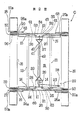
- Fig.1 is a front view of a floating dock capable of varying width according to a first embodiment of the present invention
- Fig.2 is a plan view of the same
- Fig.3 is an enlarged view for explaining essential parts of a floating member guide construction
- Fig.4 illustrates the using state of the floating dock
- Fig.5 illustrates a modified example of a floating dock
- Fig.6 is a front view of a floating dock according to a second embodiment of the present invention
- Fig.7 is a plan view of the same
- Fig.8 illustrates a construction in section of the floating member
- Fig. 9 is an enlarged view for explaining essential parts of a floating member guide construction
- Fig.10 illustrates the setetched state of operating strings of the floating dock.
- Fig. 1 shows the entire construction of a floating dock C according to the embodiment which can place a small boat B or the like in an upper or a lower trestle position.
- Reference numeral 10 designates a trestle body installed in a floating condition in water by floating members 16 which will be described later.
- the trestle body 10 comprises, in the illustrated embodiment, a pair of front and rear frame members 11, 12 desposed in front and at rear in a parallel spaced-apart relation, and a pair of connecting frame members 13, 13 in a central portion of the front and rear frame members 11, 12 to form an approximately H-shaped frame body.
- the front and rear frame members 11, 12 are designed so that their left and right portions are raised upwardly while being curved toward the central portion to form U letter-shaped frame.
- hull supporting rods 14, 15 having supporting surfaces on which a buttom B-1 of a small boat B is tiltably placed at the front and the rear portion thereof are mounted on the front and rear portions of the trestle body 10.
- the small boat B can be supported on the trestle body 10 in a stabilized state as shown in Fig. 1.
- the trestle body 10 is preferably formed of materials having high sea water-proof properties such as steel applied with anti-corrosive treatment, stainless steel, sea water-proof aluminum, etc.
- the front and rear frame members 11, 12 of the trestle body 10 have their opposite ends curved upwardly to provide rising portions, and a pot-bottom shaped boat mooring space A is formed on the trestle body 10, within which boat mooring space A, the small boat B is moored as shown in Fig. 1.
- each of the floating members 16 extending forwardly and backwardly of the front and rear frame members 11, 12 of the trestle body 10.
- the floating member 16 is each formed with ring-like guide grooves 17, 18 at locations corresponding to the front and rear frame members 11, 12 at the front and rear portions thereof.
- the trestle body 10 can be moved together with the small boat B to an upper trestle position L1 or a lower trestle position L2.
- the floating member guide means besides the above-mentioned guide means, convex fins can be provided on the floating members 16, 16 in place of the ring-like grooves 17, 18 to hold the front and rear frame members 11, 12. In short, any construction in which the floating members 16, 16 can be guided and moved will suffice.
- the floating members 16, 16 can be formed from hollow steel cans to which anti-corrosive treatment is applied or cylindrical members made of foaming styrol, it is to be noted that other shapes and materials can be also used.
- the floating members 16, 16 can be formed of hollow or buoyancy material-filled fiber reinforced plastics or the like. If the floating members 16,16 is made of a foaming material or the like wherein the surface thereof is coated with a vinyl film or the like and a core material such as wood, steel pipe or the like is made to extend through the floating members, expenses can be reduced.
- an elevating means 22 such as chain block is supported on a support post 21 for the elelvating means stood upright on the front frame member 11 of the trestle body 10.
- the elevating means 22 cooperates with operating strings 23, 24, 25, 26, 27, etc. which will be described later to form the trestle elevating device S to move the floating members 16, 16 between a position located at both sides of and a position located below the trestle body 10 so that the trestle body 10 can be elevated.
- the operating strings 24, 25 are wound around the ring-like groove 50 provided at the front end of the floating members 16, 16 (see Fig.3).
- One end of the operating strings 24, 25 is tied to central portions 60, 60 of the front frame member 11 while the other end thereof rearwardly extends through pulleys 28, 29 30 and 31 provided in the central portion of the front frame member 11 and is connected to a triangular frame member 32.
- the operating strings 26, 27 are wound around the ring-like groove 51 provided at the rear portion of the floating members 16, 16.
- One end of the operating strings 26, 27 is tied to central portions 61, 61 of the rear frame member 12 while the other end thereof rearwardly extends through the pulleys 33, 34, 35 and 36 provided in the central portion of the rear frame member 11 and is connected to a triangular frame member 37.
- the operating string 23 with one end connected to the elevating means 22 is wound on a pulley 39 on the stationary side mounted on the front frame member 11 through a pulley 38 provided on one side of the front frame member 11, and thereafter, the string 23 is wound on a running block 40 mounted on the triangular frame member 37 on the side of the rear frame member 12. Subsequently, the string 23 is again wound on the pulley 39 on the stationary side and thereafter, the end thereof is tied to a ring 41 of the running block 40.
- Reference nemeral 42 denotes an operating string for connecting both frame members 32, 37 through a pulley 43 provided in the central portion of the rear frame member 12 to provide a smooth mevement of both triangular frame members 32, 37.
- the elevating means 22 when the elevating means 22 is operated, the operating strings 23, 24, 25, 26 and 27 can be wound or loosened, whereby the floating members 16, 16 can be moved up and down along the outer surfaces of the front and rear frame members 11, 12 to easily assume the upper trestle position L1 or the lower trestle position 12 shown in Fig. 1.
- the floating members 16, 16 are positioned below the trestle body 10, and therefore, the whole width of the floating dock C can be made approximately equal to the trestle body 10. Accordingly, the small boat B or the like can be moored in the minimum mooring space, and as shown in Fig.4, many floating docks can be moored in a compact manner at the wharf or the like.
- the floating dock C is first moved forwardly from the mooring space to move the dock C into a wide space while maintaining the upper trestle condition , secondly the floating members 16, 16 can be moved toward both sides of the trestle body 10 thereby easily assuming the lower trestle operation.
- the elevating device S can be driven to thereby elevate the hull of the small boat B or the like.
- the small boat can be quickly placed at a lower trestle position and at an upper trestle position.
- the elevating device S is provided with the running block 40, the elevating force required by the elevating means 22 can be greatle reduced, and the elevating means 22 can be easily operated.
- elevating means 22 While in the present embodiment, a chain block is used as the elevating means 22, it is to be noted that the elevating means 22 is not limited thereto but other general loading apparatuses such as electric or manual winches can be of course used as the elevating means 20.
- reference numeral 50a designates a string guide groove for preventing disengagement of a floating member which is provided at a position away from the ring groove 50 at the front portion of the floating members 16, 16.
- Strings 24a, 25a for preventing disengagement of a floating member are wound on both ends of the string guide groove 50a, the strings 24a, 25a having both ends tied to rings 62, 62 provided on both ends of the front frame member 11.
- reference numeral 51a designates a string guide groove for preventing desengagement of a floating member provided at a position away from the ring groove 51 at the rear of the floating members 16, 16.
- Strings 26a, 27a for preventing desengagement of a floating member are wound on both ends of the string guide groove 51a, the strings 26a, 27a having both ends tied to rings 63, 63 provided on both ends of the front frame member 11.
- the metal rings in lieu of the strings 26a, 27a, are connected to a ring 63 by strings for preventing desengagement of a floating member so that they may be rotatably mounted in the string guied groove 51a.
- Pulleys such as the pulleys 28, 29 include approximately semi-circular pulley-like members which are mounted unrotatably on the upper ends of the front and rear frame members 11, 12 and formed of nylon resins, phenol resins and other suitable chemical materials having excellent wear resistance.
- the operating strings 15 or the like are slidably moved along the pulley-like members as described, and thereby shafts, bearings or the like which require precise working can be omitted.
- the smooth motion can be obtained merely by somewhat increasing a tractive force of the elevating means 22 and the manufacturing cost can be also reduced.
- the pulley-like members are disposed in water, water is present between the pulley-like members and the operating strings 24, 25, 26, 27, etc. Accordingly, the operating strings 24, 25, 26, 27, etc. may obtain further good sliding properties.
- bands with a groove having a recess-like section are wound about the front and rear portions of floating members 116, 116 so as to utilize the grooves of the bands as the ring-like groove 50 and the string guide groove 50a.
- a guide string or the like is secured to a guide rod or the like fixedly mounted on the trestle body 10 so that the center of gravity of the small boat B may be positioned at an approximately center between the front and rear frame members 11, 12, and the front and rear portions of the bottom B-1 of the small boat B are supported on the upper ends of the hull supporting rods 14, 14, 15, 15.
- the elevating, means 22 which conmprises a chain block is operated to wind up the operating string 23, and the operating strings 23, 24, 25, 26 and 27 are tensioned and wound up. Due to the tension exerted, the floating members 16, 16 are moved downwardly along the both side surfaces of the front and rear frame members 11, 12 to move the trestle body 10 upwardly. In association with the aforesaid upward movement of the body 10, the hull of the small boat B on the hull supporting rods 15, 15 are gradually raised, and after the hull has been raised to a predetermined level, winding of the operating string 23 or the like by the elevating means 22 is stopped to complete placing the hull at an upper trestle position, rendering the small boat stored above water.
- a separate string with a hook is suspended from the support post 21 for the elevating means, and the string can be supported at a suitable position to be used as a stopper.
- the elevating means 22 composed of a chain block encases therein a known reverse rotation preventive mechanism, the operating string 23 or the like is not automatically unwound. It is convenient to suitably mount stays or strings for guiding the hull on suitable portions of the bottom of the boat, unloding portions or floating members for the operation of placing the boat at an upper trestle position (not shown).
- the small boat B In launching the small boat so as to assume a lower trestle position, when the stopper is released and the elevating means 22 composed of a chain block is reversely operated to loosen the operating string 23 or the like, the small boat B is moved downwardly by its own weight, and when the bottom B-1 of the boat B leaves the hull supporting rods 14, 14, 15, 15, the small boat B assumes the launched state.
- Fig. 5 shows a modified example of the floating dock C according to the present embodiment, which corresponds to a relatively large load, characterized by the construction in which the tractive force required by the elevating means 22 is further reduced so that the elevating work can be done smoothly.
- the structure comprises operating means 68, 69, 70 and 71 connected to the triangular frame members 32, 37 in such a manner that operating means 24A, 258, 26C and 27D corresponding to the operating means 24, 25, 26 and 27 in the embodiments shown in Figs.1 and 2 are not directly connected to the triangular frame members 32, 37 but one end of the movable pulleys 54, 55, 56 and 57 is tied to the front and rear frame members 11, 12 while the other end is wound about the movable pulleys 54, 55, 56 and 57.
- Figs. 6 and 7 show the whole structure of the floating dock C capable of placing the small boat B or the like at an upper and a lower trestle positions according to the present embodiment.
- Reference numeral 110 designates a trestle body installed in a floating state above water by floating members 116 which will be described later.
- the trestle body 110 comprises a pair of front and rear frame members 111 and 112 disposed in front and at rear in parallelly- spaced-apart relation, and a pair of connecting frame members 113 and 113 mounted in the central portion of the front and rear frame members 111 and 112 to form an approximately H-shaped frame body.
- hull supporting rods 114, 115 having supporting surfaces capable of supporting the front and rear portions of the bottom B-1 of the small boat B are mounted on the front and rear portions of the trestle body 110.
- the small boat B can be supported on the trestle body 110 in a stabilized state as shown in Fig. 6.
- the trestle body 110 is preferably formed of material having a high sea-water-resistance such as steel applied with anti-corrosive treatment, stainless steel, and sea-water-resisting aluminum.
- the front and rear frame members 111 and 112 of the trestle body 110 have their both ends curved upwardly to define a pot bottom-like boat mooring space A similarly to the case of the first embodiment above the trestle body 110.
- the small boat B is moored within the boat mooring space A as shown in Fig. 6.
- the trestle body 110 has a pair of elongated cylindrical floating members 116, 116 extending in a longitudinal direction parallel with connecting frame members 113, 113 of the trestle body 110 and juxtaposed at opposite sides thereof, each of the floating members 116 having its front and rear ends extended forwardly and rearwardly from the front and rear frame members 111, 112 of the trestle body 110.
- each of the floating members 116 is formed such that the periphery of a floating body 116a formed from a circular foaming styrole or the like is surrounded in a water-tight manner by a pair of semi- circular surface materials with edge 116b, 116c, by which structure, a sufficient buoyancy can be assured.
- the surface materials with edge 116b, 116c are desirably formed of high sea-water-resisting materials such as fiber-reinforced plastics, steel plate applied with anti-corrosive treatment, stainless steel plate, sea-water-resisting aluminum or the like.
- the floating member 116 has a semicircular sliding member mounting frame 80 detachably connected by connecting bolts 81, 82 to the front and rear portions and to the surface material 116b with edge on one side corresponding to the front and rear frame members 111, 112, as shown in Fig. 9.
- sliding members 117, 118 for moving and guiding floating members 116,116 which are formed from arc-like plates having a shape substantially suited to the shape of left and right rising portions of the front and rear frame members 111, 112 are connected to the sliding member mounting frame 80, as shown in Fig. 9.
- the floating member moving and guiding sliding members 117, 118 have a plurality of sliding rings 83 mounted on the inner peripheral sides thereof so that they may slidably contact with outer surfaces of the left and right rising portions of the front and rear frame members 111, 112, as shown in Fig. 9.
- a plurality of small slider members formed of hard rubber for restricting the lateral movement of the floating members 116 are mounted on the back of the floating member moving and guiding sliding members 117, 118
- the sliding ring 83 has one end capable of coming into contact with rising edges 111a, 112a of the front and rear frame members 111, 112 formed from angles ( L letter shaped steel ) (see Fig. 7), whereby the movement of the floating member moving and guiding sliding members 117, 118 and the floating members 116, 116 integral therewith relative to the trestle body 110 in the lateral direction can be positibely prevented.
- the floating members 116, 116 are moved as shown in Fig. 6 by use of a trestle body elevating device S which will be described later whereby the trestle body 110 can be moved together with the small boat B to an upper trestle position L1 or a lower trestle position L2.
- Stoppers 84, 85 are provided on upper portions of both rising portions of the front and rear frame members 111, 112 to thereby positively prevent the floating member moving and guiding sliding members 117, 118 from being desengaged from the upper portion s of both the rising portions of the front and rear frame members 111, 112 at the lower trestle position L2.
- the stoppers 84, 85 are mounted vertically adjustably whereby shallow depth at a lower trestle position can be adjusted (not shown).
- Plates 208, 209 for guiding movement of a boat also serving as a reinforcing member are mounted between upper portions of both the rising portions of the front and rear frame members 111, 112.
- the front and rear frame members 111, 112 used may be of an inverse-U-shape or a pipe-like or other sectional shapes other than the shape of angle (not sliown).
- the structure of the trestle body elevating device S for moving the floating members 116, 116 upward and downward to elevate the trestle body 110 to an upper trestle position L1 and a lower trestle position L2 will be described hereinafter.
- a laterally extending lengthy operating string casing 86 is mounted between upper ends of the rising portion on one side of the front and rear frame members 111, 112 of the trestle body 110.
- An elevating means supporting post 121 is stood upright on the upper surface on the side of the front frame member of the casing 86.
- An elevating means 122 formed from a power-driven winch or the like is mounted on the upper end of the supporting post 121.
- the elevating means 122 cooperates with operating strings 89, 90. 100, 101, 108 and 109 which will be described later to form the trestle body elevating device S and to move the floating members 116, 116 between a position located at both sides of the trestle body 110 and a position located below the trestle body 110 so that the trestle body 110 may be elevated.
- the operating strings 89, 90 are wound about the pulleys 87, 88 provided below the floating member moving and guiding sliding members 117, 117 integrally mounted on the frontwardly of the floating members 116, 116, in Figs. 9 and 10.
- One ends of the operating strings 89, 90 are tied to central portions 91, 92 of the front frame member 111, while the other ends thereof are connected to a movable frame 97 which extends rearwardly through pulleys 93, 94 provided in the central portion of the front frame member 111 and which is integral with a pulley 96 formed from a running block through a multi-pulley 95.
- the operating strings 100, 101 are wound about pulleys 98, 99 provided below the floating member moving and guiding sliding members 118, 118 mounted integrally with the rear portion of the floating members 116, 116 (see Figs.9 and 10).
- One ends of the operating strings 100, 101 are tied to central portions 102, 103 of the rear frame member 112 while the other ends thereof are connected to a bifuracted frame member 107 which extends rearwardly through pulleys 104, 105 provided in the central portion of the rear frame member 112 and through a compsite pulley 106 made of a plurality of polleys likewise provided in the central portion of the rear frame member 112.
- the operating string 108 with one end connected to the bifurcated frame member 107 has the other end extended forwardly, and wound about the composite-pulley 95 made of plurality of pulleys provided on the upper surface of the front frame member 111, after which the string is connected to the movable frame 97 integral with the pulley 96.
- Reference numeral 109 designates an operating string which has one end connected to one side of the rear frame member 112, while the other end thereof is extended forwardly and wound about the pulley 96, after which it extends within the operating string casing 86 through pulleys 200, 201 provided on one side of the rear frame member 112, as shown in Fig. 10.
- the operating string 109 is guided by the pulley 202 withih the operating string casing 86, after which the other end thereof is connected to a pulley 203 formed from a runnning block.
- An operating string 205 having one end connected to a winch drum 204 constituting an elevating means 122 is wound about the pulley 203 while the other end thereof is wound through a pulley 206 provided frontwardly of the operating string casing 86, after which said other end is wound about a pulley 207 provided fronwardly of the operating string casing 86, after which it is tied to -the pulley 203.
- Reference numeral 204a denotes an electric motor.
- the floating members 116, 116 are positioned below the trestle body 110, similarly to the case of the first embodiment, whereby the whole width of the floating dock C can be made substantially equal to the trestle body 110.
- the small boat B or the like can be moored requiring the minumum mooring space, and many floating docks C can be moored in a compact manner at the wharf or the like as shown in Fig. 4.
- the floating dock C according to the second embodiment has the effects similar to those of the first embodiment by the aforementioned construction.
- the second embodiment has other effects peculiar thereto as follows:
- the aforementioned.operating strings, pulleys, runnning blocks and the like used are further increased in number depending on the loads, whereby the burden of the winch can be relieved, and manual winding instead of power winding is available.
- it may be also designed so that the construction is made to be further rigid to render the pulling burden of the end of the operating strings whilst the moving distance of the operating strings is shortened, and the operation is performed by a powerful loading machine (not shown).
- the present invention has the aforementioned constructions and functions, and therefore exhibits the following effects.
Landscapes
- Engineering & Computer Science (AREA)
- Transportation (AREA)
- Mechanical Engineering (AREA)
- Ocean & Marine Engineering (AREA)
- Bridges Or Land Bridges (AREA)
- Forklifts And Lifting Vehicles (AREA)
- Jib Cranes (AREA)
Abstract
Description
- The present invention relates to a floating dock for mooring and storing small boats or the like above the sea or water.
- Recently, marine leisure industries are increasingly completing with activation of leisure-directed mind in all sorts of fields. A trend of rapid increase also in small boats or the like appears.
- As the measures for maintaining and storing these boats, a hull is periodically landed to scrape off shells and seaweed therefrom with a great deal of labor and expenses, to apply high toxic pollution preventive coating thereto to attain a pollution preventive effect for the time being, and in case where shells or the like are adhered to the hull, the aforementioned operation is again repeated to maintain the hull in good order.
- However, expenses required for providing these measures periodically result in a huge loss in terms of material saving in consideration of an increase in consumption of fuels resulting from a poor running prior to re-coatimg.
- In view of the foregoing, the present applicant has previously disclosed, in Japanese Patent Application Unexamined Publication No. 62-128896, a water trestle machine for small boats or the like in which when a boat is not in use, even on the sea, the entire hull can be always held above the water to obtain a permanent anti-pollution effect while when the boat is to be used, the boat can be easily lowered down.
- Such a water trestle machine for small boats or the like still has the following problem.
- That is, in such a water trestle machine, floating members are located on opposite sides of the trestle body and the floating members are merely vertically moved up and down along the oppotite sides, to place the hull in an upper trestle position and a lower trestle position. Therefore, the water trestle machine has required a width which is much wider than the hull to be moved upwardly or downwardly.
- This requires a wide mooring space in a wharf, and as a result, the number of mooring units which can be installed in the wharf is restricted.
- It is an object of the present invention to provide a floating dock of which width can be varied.
- The present invention relates to a floating dock capable of varying a width comprising a trestle body formed at its upper surface with a hull place surface, floating members disposed movably up and down in contact with body sides of the trestle body, and a trestle elevating device capable of moving the floating members from a lower trestle position located at both sides of the trestle body to an upper trestle position located below the trestle body.
- Fig.1 is a front view of a floating dock capable of varying width according to a first embodiment of the present invention; Fig.2 is a plan view of the same; Fig.3 is an enlarged view for explaining essential parts of a floating member guide construction; Fig.4 illustrates the using state of the floating dock; Fig.5 illustrates a modified example of a floating dock; Fig.6 is a front view of a floating dock according to a second embodiment of the present invention; Fig.7 is a plan view of the same; Fig.8 illustrates a construction in section of the floating member; Fig. 9 is an enlarged view for explaining essential parts of a floating member guide construction; and Fig.10 illustrates the setetched state of operating strings of the floating dock.
- For describing the present invention in further detail, the present invention will be described hereinafter in accordance with the embodiments shown in the accompanied drawings.
- Fig. 1 shows the entire construction of a floating dock C according to the embodiment which can place a small boat B or the like in an upper or a lower trestle position.
Reference numeral 10 designates a trestle body installed in a floating condition in water by floatingmembers 16 which will be described later. Thetrestle body 10 comprises, in the illustrated embodiment, a pair of front andrear frame members frame members rear frame members - The front and
rear frame members - As shown in Fig.1 and 2,
hull supporting rods trestle body 10. - With such a construction as described above, the small boat B can be supported on the
trestle body 10 in a stabilized state as shown in Fig. 1. - The
trestle body 10 is preferably formed of materials having high sea water-proof properties such as steel applied with anti-corrosive treatment, stainless steel, sea water-proof aluminum, etc. - As shown Fig. 1, the front and
rear frame members trestle body 10 have their opposite ends curved upwardly to provide rising portions, and a pot-bottom shaped boat mooring space A is formed on thetrestle body 10, within which boat mooring space A, the small boat B is moored as shown in Fig. 1. - The
floating members - Along the opposite sides of the
trestle body 10, there are juxtaposed a pair of elongated cylindrical floatingmembers frame members trestle body 10, the front and rear ends of each of thefloating members 16 extending forwardly and backwardly of the front andrear frame members trestle body 10. - The
floating member 16 is each formed with ring-like guide grooves rear frame members - On the other hand, on the outer peripheral surfaces of the front and
rear frame members like guide grooves guide projections such projections like grooves - When the floating
members projections trestle body 10 can be moved together with the small boat B to an upper trestle position L1 or a lower trestle position L2. - With respect to the floating member guide means, besides the above-mentioned guide means, convex fins can be provided on the floating
members like grooves rear frame members members - While in the present embodiment, the floating
members - For example, as for materials, the floating
members members - Next, the construction of the trestle elevating device S for moving the
floating members trestle body 10 at an upper trestle position L1 and at a lower trestle position L2 will be described hereinafter. - As shown in the drawing, an
elevating means 22 such as chain block is supported on asupport post 21 for the elelvating means stood upright on thefront frame member 11 of thetrestle body 10. The elevatingmeans 22 cooperates withoperating strings members trestle body 10 so that thetrestle body 10 can be elevated. - That is, in Fig.2, the
operating strings like groove 50 provided at the front end of thefloating members 16, 16 (see Fig.3). One end of theoperating strings central portions front frame member 11 while the other end thereof rearwardly extends throughpulleys front frame member 11 and is connected to atriangular frame member 32. - On the other hand, the
operating strings like groove 51 provided at the rear portion of the floatingmembers - One end of the
operating strings central portions rear frame member 12 while the other end thereof rearwardly extends through thepulleys rear frame member 11 and is connected to atriangular frame member 37. - The
operating string 23 with one end connected to theelevating means 22 is wound on apulley 39 on the stationary side mounted on thefront frame member 11 through apulley 38 provided on one side of thefront frame member 11, and thereafter, thestring 23 is wound on a runningblock 40 mounted on thetriangular frame member 37 on the side of therear frame member 12. Subsequently, thestring 23 is again wound on thepulley 39 on the stationary side and thereafter, the end thereof is tied to aring 41 of therunning block 40. - Reference nemeral 42 denotes an operating string for connecting both
frame members pulley 43 provided in the central portion of therear frame member 12 to provide a smooth mevement of bothtriangular frame members - With the construction as described above, when the
elevating means 22 is operated, theoperating strings members rear frame members lower trestle position 12 shown in Fig. 1. - In the present embodiment, at the time of attaining the upper trestle position, the floating
members trestle body 10, and therefore, the whole width of the floating dock C can be made approximately equal to thetrestle body 10. Accordingly, the small boat B or the like can be moored in the minimum mooring space, and as shown in Fig.4, many floating docks can be moored in a compact manner at the wharf or the like. - On the other hand, at the time of attaining the lower trestle position, as shown in Fig. 4, the floating dock C is first moved forwardly from the mooring space to move the dock C into a wide space while maintaining the upper trestle condition , secondly the floating
members trestle body 10 thereby easily assuming the lower trestle operation. - That is, in the present embodiment, the elevating device S can be driven to thereby elevate the hull of the small boat B or the like. When leaving and returning to a port, the small boat can be quickly placed at a lower trestle position and at an upper trestle position.
- Furthermore, in the present embodiment, since the elevating device S is provided with the running
block 40, the elevating force required by theelevating means 22 can be greatle reduced, and theelevating means 22 can be easily operated. - While in the present embodiment, a chain block is used as the
elevating means 22, it is to be noted that theelevating means 22 is not limited thereto but other general loading apparatuses such as electric or manual winches can be of course used as theelevating means 20. - In the present embodiment,
reference numeral 50a designates a string guide groove for preventing disengagement of a floating member which is provided at a position away from thering groove 50 at the front portion of thefloating members Strings string guide groove 50a, thestrings front frame member 11. - On the other hand,
reference numeral 51a designates a string guide groove for preventing desengagement of a floating member provided at a position away from thering groove 51 at the rear of thefloating members -
Strings string guide groove 51a, thestrings rings front frame member 11. - With the construction as described above, in moving the floating
members members rear frame members - Moreover, it is noted that with respect to the stopper mechanism, the metal rings, in lieu of the
strings ring 63 by strings for preventing desengagement of a floating member so that they may be rotatably mounted in the string guiedgroove 51a. - Pulleys such as the
pulleys rear frame members operating strings 15 or the like are slidably moved along the pulley-like members as described, and thereby shafts, bearings or the like which require precise working can be omitted. The smooth motion can be obtained merely by somewhat increasing a tractive force of the elevatingmeans 22 and the manufacturing cost can be also reduced. - Since the pulley-like members are disposed in water, water is present between the pulley-like members and the operating strings 24, 25, 26, 27, etc. Accordingly, the operating strings 24, 25, 26, 27, etc. may obtain further good sliding properties.
- It is to be noted that, in the above-described construction, instead of the provision of the ring-
like groove 50 and thestring guide groove 50a, bands with a groove having a recess-like section are wound about the front and rear portions of floatingmembers like groove 50 and thestring guide groove 50a. - The method of using the floating dock C having the above-described constriction will be described in detail with particular reference to Fig. 4.
- First, in placing the small boat B at an upper trestle position, a guide string or the like is secured to a guide rod or the like fixedly mounted on the
trestle body 10 so that the center of gravity of the small boat B may be positioned at an approximately center between the front andrear frame members hull supporting rods - Then, the elevating, means 22 which conmprises a chain block is operated to wind up the operating
string 23, and the operating strings 23, 24, 25, 26 and 27 are tensioned and wound up. Due to the tension exerted, the floatingmembers rear frame members trestle body 10 upwardly. In association with the aforesaid upward movement of thebody 10, the hull of the small boat B on thehull supporting rods string 23 or the like by the elevatingmeans 22 is stopped to complete placing the hull at an upper trestle position, rendering the small boat stored above water. - As for the stopper, a separate string with a hook is suspended from the
support post 21 for the elevating means, and the string can be supported at a suitable position to be used as a stopper. - Since the elevating means 22 composed of a chain block encases therein a known reverse rotation preventive mechanism, the operating
string 23 or the like is not automatically unwound. It is convenient to suitably mount stays or strings for guiding the hull on suitable portions of the bottom of the boat, unloding portions or floating members for the operation of placing the boat at an upper trestle position (not shown). - In launching the small boat so as to assume a lower trestle position, when the stopper is released and the elevating means 22 composed of a chain block is reversely operated to loosen the operating
string 23 or the like, the small boat B is moved downwardly by its own weight, and when the bottom B-1 of the boat B leaves thehull supporting rods - Fig. 5 shows a modified example of the floating dock C according to the present embodiment, which corresponds to a relatively large load, characterized by the construction in which the tractive force required by the elevating
means 22 is further reduced so that the elevating work can be done smoothly. - That is, in Fig. 5, the structure comprises operating means 68, 69, 70 and 71 connected to the
triangular frame members triangular frame members movable pulleys rear frame members movable pulleys - As described above, in case of a relatively heavy load, many pulleys and string means can be used to extremely lighten the load. However, in this case, since the length of the string means becomes long, winches are desirable as elevating means.
- Figs. 6 and 7 show the whole structure of the floating dock C capable of placing the small boat B or the like at an upper and a lower trestle positions according to the present embodiment.
Reference numeral 110 designates a trestle body installed in a floating state above water by floatingmembers 116 which will be described later. - In the illustrated embodiment, the
trestle body 110 comprises a pair of front andrear frame members frame members rear frame members - As shown in Figs. 6 and 7,
hull supporting rods trestle body 110. - With such a structure as described above, the small boat B can be supported on the
trestle body 110 in a stabilized state as shown in Fig. 6. - The
trestle body 110 is preferably formed of material having a high sea-water-resistance such as steel applied with anti-corrosive treatment, stainless steel, and sea-water-resisting aluminum. - As shown in Fig. 6, the front and
rear frame members trestle body 110 have their both ends curved upwardly to define a pot bottom-like boat mooring space A similarly to the case of the first embodiment above thetrestle body 110. The small boat B is moored within the boat mooring space A as shown in Fig. 6. - The floating
members - As shown in Fig. 6, the
trestle body 110 has a pair of elongated cylindrical floatingmembers frame members trestle body 110 and juxtaposed at opposite sides thereof, each of the floatingmembers 116 having its front and rear ends extended forwardly and rearwardly from the front andrear frame members trestle body 110. - As shown in Fig. 8, each of the floating
members 116 is formed such that the periphery of a floatingbody 116a formed from a circular foaming styrole or the like is surrounded in a water-tight manner by a pair of semi- circular surface materials withedge - The surface materials with
edge - The floating
member 116 has a semicircular slidingmember mounting frame 80 detachably connected by connectingbolts surface material 116b with edge on one side corresponding to the front andrear frame members - On the other hand, sliding
members rear frame members member mounting frame 80, as shown in Fig. 9. - The floating member moving and guiding sliding
members rings 83 mounted on the inner peripheral sides thereof so that they may slidably contact with outer surfaces of the left and right rising portions of the front andrear frame members - A plurality of small slider members (not shown) formed of hard rubber for restricting the lateral movement of the floating
members 116 are mounted on the back of the floating member moving and guiding slidingmembers - The sliding
ring 83 has one end capable of coming into contact with risingedges rear frame members members members trestle body 110 in the lateral direction can be positibely prevented. - Accordingly, the floating
members trestle body 110 can be moved together with the small boat B to an upper trestle position L1 or a lower trestle position L2. -
Stoppers rear frame members members rear frame members - The
stoppers -
Plates rear frame members - The front and
rear frame members - The structure of the trestle body elevating device S for moving the floating
members trestle body 110 to an upper trestle position L1 and a lower trestle position L2 will be described hereinafter. - As shown in Fig. 6, a laterally extending lengthy operating string casing 86 is mounted between upper ends of the rising portion on one side of the front and
rear frame members trestle body 110. An elevatingmeans supporting post 121 is stood upright on the upper surface on the side of the front frame member of thecasing 86. An elevating means 122 formed from a power-driven winch or the like is mounted on the upper end of the supportingpost 121. - The elevating means 122 cooperates with operating
strings members trestle body 110 and a position located below thetrestle body 110 so that thetrestle body 110 may be elevated. - That is, the operating strings 89, 90 are wound about the
pulleys members members - One ends of the operating strings 89, 90 are tied to
central portions front frame member 111, while the other ends thereof are connected to amovable frame 97 which extends rearwardly throughpulleys front frame member 111 and which is integral with apulley 96 formed from a running block through a multi-pulley 95. - On the other hand, the operating
strings pulleys members members 116, 116 (see Figs.9 and 10). - One ends of the operating strings 100, 101 are tied to
central portions rear frame member 112 while the other ends thereof are connected to abifuracted frame member 107 which extends rearwardly throughpulleys rear frame member 112 and through acompsite pulley 106 made of a plurality of polleys likewise provided in the central portion of therear frame member 112. - The operating
string 108 with one end connected to thebifurcated frame member 107 has the other end extended forwardly, and wound about the composite-pulley 95 made of plurality of pulleys provided on the upper surface of thefront frame member 111, after which the string is connected to themovable frame 97 integral with thepulley 96. -
Reference numeral 109 designates an operating string which has one end connected to one side of therear frame member 112, while the other end thereof is extended forwardly and wound about thepulley 96, after which it extends within the operating string casing 86 throughpulleys rear frame member 112, as shown in Fig. 10. - The operating
string 109 is guided by thepulley 202 withih the operating string casing 86, after which the other end thereof is connected to a pulley 203 formed from a runnning block. - An
operating string 205 having one end connected to awinch drum 204 constituting an elevatingmeans 122 is wound about the pulley 203 while the other end thereof is wound through apulley 206 provided frontwardly of the operating string casing 86, after which said other end is wound about apulley 207 provided fronwardly of the operating string casing 86, after which it is tied to -the pulley 203.Reference numeral 204a denotes an electric motor. - With the construction as described above, when the elevating means 122 is operated, various operating
strings members rear frame members - In the present embodiment, as shown in Fig. 6, at the time of placing the boat at an upper trestle position, the floating
members trestle body 110, similarly to the case of the first embodiment, whereby the whole width of the floating dock C can be made substantially equal to thetrestle body 110. - Accordingly, the small boat B or the like can be moored requiring the minumum mooring space, and many floating docks C can be moored in a compact manner at the wharf or the like as shown in Fig. 4.
- As described above, the floating dock C according to the second embodiment has the effects similar to those of the first embodiment by the aforementioned construction.
- In addition, the second embodiment has other effects peculiar thereto as follows:
- (1) Unlike the case of the first embodiment, the floating
member 116 need not be provided in its peripheral surface with thering groove 50 and thestring guide groove 51a for preventing disengagement of a floating member, and has the edge on the side opposed through 180° . Therefore, the rigidity of the floatingmember 116 can be greatly enhanced, and the strength can be increased. - (2) Since the floating
member 116 can be formed merely in a manner such that the floatingmember body 116a is surrounded by a pair of surface materials with edge 106b, 106c, it is possible to manufacture the floatingmember 116 at less cost. - (3) By use of the floating member moving and guiding sliding
members members trestle body 110 at upper and lower trestle positions can be easily and positively accomplished. - (4) Since the operating strings 89, 90, 100 and 101 do not rub the outer surfaces of the front and
rear frame members trestle body 110, it is possible to minimize the injuring of the frame members 111,112 of thetrestle body 110. - (5) The edge of the floating
member 116 in water provides a resitance against rolling caused by wind and wave and can also serve as a stabilizer, which is the merit thereof. - While the present invention has been described with reference to two embodiments, it is to be noted that the present invention is not in any way limited to the above-described embodiments. For example, the following modifications are taken into consideration.
- That is, in order to avoid an insufficient rotation of the ring shafts or the like close to the sea level resulting from solidification of salts under the natural phenomenon caused by wind and waves on the sea, a construction in which these elements are disposed under water is possible and desirable as measures for sea-breezes of a mechanical portion depending on the environment of sea surface used for the floating dock according to the present invention.
- On the other hand, it is also possible to provide a construction in which ring shafts or the like which should be present above the sea level are provided at a position above the sea level as high as possible, which is extremely preferable in view of maintenence.
- Furthermore, with respect to the elevating operation, the aforementioned.operating strings, pulleys, runnning blocks and the like used are further increased in number depending on the loads, whereby the burden of the winch can be relieved, and manual winding instead of power winding is available. Conversely, it may be also designed so that the construction is made to be further rigid to render the pulling burden of the end of the operating strings whilst the moving distance of the operating strings is shortened, and the operation is performed by a powerful loading machine (not shown).
- The present invention has the aforementioned constructions and functions, and therefore exhibits the following effects.
- (1) Since at the time of placing the boat at an upper trestle position, the whole width of the floating dock can be made to be equal to that of the trestle body, the minimum mooring space will suffice and many floating docks can be moored at the wharf or the like. On the other hand, at the time of placing the boat at a lower trestle position, the floating dock is once moved frontwardly from the mooring space while maintaining the upper trestle state, and after the dock has been moved out to a wide space, the floating members are moved toward both sides of the trestle body whereby the operation of placing the boat at a lower trestle position can be effected.
- (2) The hull can be elevated merely by driving the trestle body elevating device, and at the time of leaving and returning to a port, the placement of the boat at upper and lower trestle positions can be quickly accomplished.
Claims (4)
Applications Claiming Priority (4)
| Application Number | Priority Date | Filing Date | Title |
|---|---|---|---|
| JP8095988 | 1988-03-31 | ||
| JP80959/88 | 1988-03-31 | ||
| JP1028439A JPH0764310B2 (en) | 1988-03-31 | 1989-02-06 | Ukifune with variable width |
| JP128439/89 | 1989-02-06 |
Publications (3)
| Publication Number | Publication Date |
|---|---|
| EP0366809A1 true EP0366809A1 (en) | 1990-05-09 |
| EP0366809A4 EP0366809A4 (en) | 1990-07-03 |
| EP0366809B1 EP0366809B1 (en) | 1992-06-17 |
Family
ID=26366547
Family Applications (1)
| Application Number | Title | Priority Date | Filing Date |
|---|---|---|---|
| EP89904214A Expired EP0366809B1 (en) | 1988-03-31 | 1989-03-30 | Floating dock adjustable in width |
Country Status (4)
| Country | Link |
|---|---|
| US (1) | US5078071A (en) |
| EP (1) | EP0366809B1 (en) |
| JP (1) | JPH0764310B2 (en) |
| WO (1) | WO1989009162A1 (en) |
Cited By (3)
| Publication number | Priority date | Publication date | Assignee | Title |
|---|---|---|---|---|
| EP0833771A4 (en) * | 1995-06-23 | 2000-02-02 | Michael Kilpatrick Meek | Improved docking apparatus |
| RU2197407C1 (en) * | 2001-05-21 | 2003-01-27 | Общество с ограниченной ответственностью "Компания "Байкал-Волга" | Floating dock and method of self-docking |
| ITCZ20100001A1 (en) * | 2010-02-16 | 2011-08-17 | Luigino Muraca | PONTILE SUSPENDED SELF-LEVELING MODULAR ITINERANT WITH INTEGRATED STRUCTURES LIFT-BOATS |
Families Citing this family (9)
| Publication number | Priority date | Publication date | Assignee | Title |
|---|---|---|---|---|
| US5269246A (en) * | 1991-04-01 | 1993-12-14 | Metro Machine Corporation | Vessel hull construction and method |
| JP2685115B2 (en) * | 1993-08-31 | 1997-12-03 | 信隆 三浦 | Ukifune with variable width |
| US5799916A (en) * | 1996-02-14 | 1998-09-01 | Lechner; Donald A. | Bracket for floating docks and rafts |
| US5860379A (en) * | 1997-08-22 | 1999-01-19 | Moody; Kenneth D. | Inflatable floating boat lift |
| US6823809B2 (en) * | 2001-03-16 | 2004-11-30 | Sunstream Corporation | Floating watercraft lift apparatus and method |
| AU2007227334A1 (en) * | 2006-03-23 | 2007-09-27 | Sunstream Corporation | Failsafe watercraft lift with convertible leveling system |
| US12187394B2 (en) * | 2016-08-02 | 2025-01-07 | Autolift, LLC | Watercraft lift system and method |
| US10315738B2 (en) * | 2016-11-30 | 2019-06-11 | E-Z-Dock, Inc. | Small watercraft launch |
| CN109673575B (en) * | 2019-01-25 | 2023-09-05 | 无锡洛康智能科技有限公司 | A water type aerator |
Family Cites Families (7)
| Publication number | Priority date | Publication date | Assignee | Title |
|---|---|---|---|---|
| US3265024A (en) * | 1965-06-14 | 1966-08-09 | Charles W Kramlich | Boat lift |
| US3412702A (en) * | 1966-07-05 | 1968-11-26 | James M. Mann | Floating dry dock for small boats |
| US3415212A (en) * | 1967-04-07 | 1968-12-10 | Hennig Irving | Floating drydock |
| US3777691A (en) * | 1971-06-25 | 1973-12-11 | W Beale | Marine elevator |
| AU4045778A (en) * | 1977-10-13 | 1980-04-17 | Thom D S | Floating dock |
| JPS62128896A (en) * | 1985-11-29 | 1987-06-11 | Nobutaka Miura | Cradle for small-sized vessel |
| US4732102A (en) * | 1986-03-10 | 1988-03-22 | Holman Clifford W | Portable, self-contained, self-adjustable craft lift and wet/dry storage system |
-
1989
- 1989-02-06 JP JP1028439A patent/JPH0764310B2/en not_active Expired - Lifetime
- 1989-03-30 WO PCT/JP1989/000334 patent/WO1989009162A1/en not_active Ceased
- 1989-03-30 US US07/445,652 patent/US5078071A/en not_active Expired - Fee Related
- 1989-03-30 EP EP89904214A patent/EP0366809B1/en not_active Expired
Non-Patent Citations (2)
| Title |
|---|
| No further relevant documents have been disclosed. * |
| See also references of WO8909162A1 * |
Cited By (3)
| Publication number | Priority date | Publication date | Assignee | Title |
|---|---|---|---|---|
| EP0833771A4 (en) * | 1995-06-23 | 2000-02-02 | Michael Kilpatrick Meek | Improved docking apparatus |
| RU2197407C1 (en) * | 2001-05-21 | 2003-01-27 | Общество с ограниченной ответственностью "Компания "Байкал-Волга" | Floating dock and method of self-docking |
| ITCZ20100001A1 (en) * | 2010-02-16 | 2011-08-17 | Luigino Muraca | PONTILE SUSPENDED SELF-LEVELING MODULAR ITINERANT WITH INTEGRATED STRUCTURES LIFT-BOATS |
Also Published As
| Publication number | Publication date |
|---|---|
| EP0366809A4 (en) | 1990-07-03 |
| JPH02169392A (en) | 1990-06-29 |
| EP0366809B1 (en) | 1992-06-17 |
| JPH0764310B2 (en) | 1995-07-12 |
| US5078071A (en) | 1992-01-07 |
| WO1989009162A1 (en) | 1989-10-05 |
Similar Documents
| Publication | Publication Date | Title |
|---|---|---|
| EP0366809B1 (en) | Floating dock adjustable in width | |
| US20080276851A1 (en) | Floating lift for watercraft | |
| US3822559A (en) | Controlled yield stinger | |
| US5829376A (en) | Outrigger watercraft | |
| JP4394453B2 (en) | Ocean mooring boat | |
| CN103339027A (en) | Apparatus to launch and recover a boat | |
| US6964239B2 (en) | Modular floating boat lift | |
| US4048686A (en) | Buoyancy device and method | |
| US5522671A (en) | Hydraulic boat lift | |
| US4748927A (en) | Means and a method for positioning a stabilizer on a boat | |
| NL8101670A (en) | METHOD AND LINE FOR LAYING A PIPE | |
| KR101335249B1 (en) | Floating support and pipeline laying vessel having the same | |
| US4697533A (en) | Device for hoisting boats on board ships | |
| WO1987000136A1 (en) | Splitwing keel | |
| US3406649A (en) | Method and apparatus for drydocking a boat hull or other floating structure in a body of water | |
| JPS63137096A (en) | Water surface frame for small ship and the like | |
| US4207639A (en) | Floating terminal for loading and/or unloading tankers | |
| KR20160057791A (en) | Improved Hydraulic Cylinder-Operated Floating Watercraft Lift Apparatus For Raising Or Lowering The Watercraft | |
| CN115367064A (en) | Ocean platform transportation device | |
| US5373801A (en) | Submerged weight retrieval device | |
| JPH075036Y2 (en) | Small boats, etc. | |
| JPS61249894A (en) | Hanging down/lifting up device for underwater observation apparatus in ship | |
| US3906879A (en) | Marine vessel having development and recovery device | |
| WO1997048593A1 (en) | Means for varying the shape of a boat hull | |
| EP3978353B1 (en) | Hull protection device |
Legal Events
| Date | Code | Title | Description |
|---|---|---|---|
| PUAI | Public reference made under article 153(3) epc to a published international application that has entered the european phase |
Free format text: ORIGINAL CODE: 0009012 |
|
| 17P | Request for examination filed |
Effective date: 19891204 |
|
| AK | Designated contracting states |
Kind code of ref document: A1 Designated state(s): FR GB IT SE |
|
| A4 | Supplementary search report drawn up and despatched |
Effective date: 19900703 |
|
| 17Q | First examination report despatched |
Effective date: 19910805 |
|
| GRAA | (expected) grant |
Free format text: ORIGINAL CODE: 0009210 |
|
| ITF | It: translation for a ep patent filed | ||
| AK | Designated contracting states |
Kind code of ref document: B1 Designated state(s): FR GB IT SE |
|
| ET | Fr: translation filed | ||
| PLBE | No opposition filed within time limit |
Free format text: ORIGINAL CODE: 0009261 |
|
| STAA | Information on the status of an ep patent application or granted ep patent |
Free format text: STATUS: NO OPPOSITION FILED WITHIN TIME LIMIT |
|
| 26N | No opposition filed | ||
| EAL | Se: european patent in force in sweden |
Ref document number: 89904214.7 |
|
| PGFP | Annual fee paid to national office [announced via postgrant information from national office to epo] |
Ref country code: FR Payment date: 19950320 Year of fee payment: 7 |
|
| PGFP | Annual fee paid to national office [announced via postgrant information from national office to epo] |
Ref country code: SE Payment date: 19950321 Year of fee payment: 7 |
|
| PGFP | Annual fee paid to national office [announced via postgrant information from national office to epo] |
Ref country code: GB Payment date: 19950601 Year of fee payment: 7 |
|
| PG25 | Lapsed in a contracting state [announced via postgrant information from national office to epo] |
Ref country code: GB Effective date: 19960330 |
|
| PG25 | Lapsed in a contracting state [announced via postgrant information from national office to epo] |
Ref country code: SE Effective date: 19960331 |
|
| GBPC | Gb: european patent ceased through non-payment of renewal fee |
Effective date: 19960330 |
|
| PG25 | Lapsed in a contracting state [announced via postgrant information from national office to epo] |
Ref country code: FR Effective date: 19961129 |
|
| EUG | Se: european patent has lapsed |
Ref document number: 89904214.7 |
|
| REG | Reference to a national code |
Ref country code: FR Ref legal event code: ST |
|
| PG25 | Lapsed in a contracting state [announced via postgrant information from national office to epo] |
Ref country code: IT Free format text: LAPSE BECAUSE OF NON-PAYMENT OF DUE FEES;WARNING: LAPSES OF ITALIAN PATENTS WITH EFFECTIVE DATE BEFORE 2007 MAY HAVE OCCURRED AT ANY TIME BEFORE 2007. THE CORRECT EFFECTIVE DATE MAY BE DIFFERENT FROM THE ONE RECORDED. Effective date: 20050330 |