EP0366696B1 - Procedure for controlling a radiation source and controllable radiation source - Google Patents
Procedure for controlling a radiation source and controllable radiation source Download PDFInfo
- Publication number
- EP0366696B1 EP0366696B1 EP88905853A EP88905853A EP0366696B1 EP 0366696 B1 EP0366696 B1 EP 0366696B1 EP 88905853 A EP88905853 A EP 88905853A EP 88905853 A EP88905853 A EP 88905853A EP 0366696 B1 EP0366696 B1 EP 0366696B1
- Authority
- EP
- European Patent Office
- Prior art keywords
- radiation
- wavelength range
- led
- radiation source
- intensity
- Prior art date
- Legal status (The legal status is an assumption and is not a legal conclusion. Google has not performed a legal analysis and makes no representation as to the accuracy of the status listed.)
- Expired - Lifetime
Links
- 230000005855 radiation Effects 0.000 title claims abstract description 148
- 238000000034 method Methods 0.000 title claims abstract description 20
- 230000003287 optical effect Effects 0.000 claims abstract description 33
- 230000001276 controlling effect Effects 0.000 claims abstract description 5
- 230000001105 regulatory effect Effects 0.000 claims abstract description 4
- 230000003213 activating effect Effects 0.000 claims abstract description 3
- 238000005259 measurement Methods 0.000 claims description 18
- 230000005540 biological transmission Effects 0.000 claims description 8
- 239000000835 fiber Substances 0.000 claims description 5
- 230000001419 dependent effect Effects 0.000 claims description 3
- 238000001228 spectrum Methods 0.000 abstract description 17
- 239000004065 semiconductor Substances 0.000 abstract description 7
- 238000003491 array Methods 0.000 abstract 1
- 238000013461 design Methods 0.000 description 4
- 238000010586 diagram Methods 0.000 description 2
- 238000004364 calculation method Methods 0.000 description 1
- 238000010276 construction Methods 0.000 description 1
- 238000011161 development Methods 0.000 description 1
- 239000006185 dispersion Substances 0.000 description 1
- 238000005265 energy consumption Methods 0.000 description 1
- 238000005516 engineering process Methods 0.000 description 1
- 238000001914 filtration Methods 0.000 description 1
- 230000017525 heat dissipation Effects 0.000 description 1
- 230000010354 integration Effects 0.000 description 1
- 239000011159 matrix material Substances 0.000 description 1
- 238000012544 monitoring process Methods 0.000 description 1
- 238000004451 qualitative analysis Methods 0.000 description 1
- 238000004445 quantitative analysis Methods 0.000 description 1
- 230000003595 spectral effect Effects 0.000 description 1
- 239000000126 substance Substances 0.000 description 1
- 230000001360 synchronised effect Effects 0.000 description 1
Images


Classifications
-
- G—PHYSICS
- G01—MEASURING; TESTING
- G01N—INVESTIGATING OR ANALYSING MATERIALS BY DETERMINING THEIR CHEMICAL OR PHYSICAL PROPERTIES
- G01N21/00—Investigating or analysing materials by the use of optical means, i.e. using sub-millimetre waves, infrared, visible or ultraviolet light
- G01N21/17—Systems in which incident light is modified in accordance with the properties of the material investigated
- G01N21/25—Colour; Spectral properties, i.e. comparison of effect of material on the light at two or more different wavelengths or wavelength bands
- G01N21/255—Details, e.g. use of specially adapted sources, lighting or optical systems
-
- G—PHYSICS
- G01—MEASURING; TESTING
- G01J—MEASUREMENT OF INTENSITY, VELOCITY, SPECTRAL CONTENT, POLARISATION, PHASE OR PULSE CHARACTERISTICS OF INFRARED, VISIBLE OR ULTRAVIOLET LIGHT; COLORIMETRY; RADIATION PYROMETRY
- G01J1/00—Photometry, e.g. photographic exposure meter
- G01J1/02—Details
- G01J1/08—Arrangements of light sources specially adapted for photometry standard sources, also using luminescent or radioactive material
-
- G—PHYSICS
- G01—MEASURING; TESTING
- G01J—MEASUREMENT OF INTENSITY, VELOCITY, SPECTRAL CONTENT, POLARISATION, PHASE OR PULSE CHARACTERISTICS OF INFRARED, VISIBLE OR ULTRAVIOLET LIGHT; COLORIMETRY; RADIATION PYROMETRY
- G01J1/00—Photometry, e.g. photographic exposure meter
- G01J1/10—Photometry, e.g. photographic exposure meter by comparison with reference light or electric value provisionally void
- G01J1/20—Photometry, e.g. photographic exposure meter by comparison with reference light or electric value provisionally void intensity of the measured or reference value being varied to equalise their effects at the detectors, e.g. by varying incidence angle
- G01J1/28—Photometry, e.g. photographic exposure meter by comparison with reference light or electric value provisionally void intensity of the measured or reference value being varied to equalise their effects at the detectors, e.g. by varying incidence angle using variation of intensity or distance of source
- G01J1/30—Photometry, e.g. photographic exposure meter by comparison with reference light or electric value provisionally void intensity of the measured or reference value being varied to equalise their effects at the detectors, e.g. by varying incidence angle using variation of intensity or distance of source using electric radiation detectors
- G01J1/32—Photometry, e.g. photographic exposure meter by comparison with reference light or electric value provisionally void intensity of the measured or reference value being varied to equalise their effects at the detectors, e.g. by varying incidence angle using variation of intensity or distance of source using electric radiation detectors adapted for automatic variation of the measured or reference value
-
- G—PHYSICS
- G01—MEASURING; TESTING
- G01J—MEASUREMENT OF INTENSITY, VELOCITY, SPECTRAL CONTENT, POLARISATION, PHASE OR PULSE CHARACTERISTICS OF INFRARED, VISIBLE OR ULTRAVIOLET LIGHT; COLORIMETRY; RADIATION PYROMETRY
- G01J3/00—Spectrometry; Spectrophotometry; Monochromators; Measuring colours
- G01J3/02—Details
- G01J3/0256—Compact construction
- G01J3/0259—Monolithic
-
- G—PHYSICS
- G01—MEASURING; TESTING
- G01J—MEASUREMENT OF INTENSITY, VELOCITY, SPECTRAL CONTENT, POLARISATION, PHASE OR PULSE CHARACTERISTICS OF INFRARED, VISIBLE OR ULTRAVIOLET LIGHT; COLORIMETRY; RADIATION PYROMETRY
- G01J3/00—Spectrometry; Spectrophotometry; Monochromators; Measuring colours
- G01J3/02—Details
- G01J3/10—Arrangements of light sources specially adapted for spectrometry or colorimetry
-
- G—PHYSICS
- G01—MEASURING; TESTING
- G01N—INVESTIGATING OR ANALYSING MATERIALS BY DETERMINING THEIR CHEMICAL OR PHYSICAL PROPERTIES
- G01N2201/00—Features of devices classified in G01N21/00
- G01N2201/06—Illumination; Optics
- G01N2201/062—LED's
- G01N2201/0621—Supply
Definitions
- the present invention relates to a method for controlling a radiation source which comprises a plurality of light-emitting diodes (LEDs); the method comprising a step of selectively driving one of said LEDs for producing output radiation within a selected wavelength range which is associated with the selected one of said LEDs.
- a radiation source which comprises a plurality of light-emitting diodes (LEDs)
- the method comprising a step of selectively driving one of said LEDs for producing output radiation within a selected wavelength range which is associated with the selected one of said LEDs.
- the present invention also relates to a controllable radiation source for producing output radiation within a selected wavelength range, comprising: a plurality of light-emitting diodes (LEDs); an output slit or equivalent; an optical dispersing element arranged in an optical path between said plurality of light-emitting diodes and said output slit, the optical dispersing element being adapted for receiving radiation and refracting the received radiation in a direction dependent on the wavelength of the received radiation; and a driver and control means for selectively driving one of said LEDs.
- LEDs light-emitting diodes
- an output slit or equivalent an optical dispersing element arranged in an optical path between said plurality of light-emitting diodes and said output slit, the optical dispersing element being adapted for receiving radiation and refracting the received radiation in a direction dependent on the wavelength of the received radiation
- a driver and control means for selectively driving one of said LEDs.
- a radiation source of the kind described is used for instance in spectrometers and photometers. In frequent cases the radiation source is the most significant factor limiting the capacity of performance and usability of an instrument. In apparatus meant to be used in industrial conditions, as radiation source have usually been employed thermal radiators, such as sources based on an incandescent filament, for instance. Their problem is, however, poor optical efficiency and consequent high heat dissipation, as well as poor vibration tolerance, short service, life and difficulty of modulation.
- LEDs are nearly ideal radiation sources for spectrometers in view of their narrow spectrum. However, high price and poor stability are their problems. It is also a fact that the selection of standard wavelengths is scanty, particularly in the near IR range. LEDs enable, owing to their wider radiation spectrum, a considerably wider wavelength range to be covered, and they are also lower in price. The spectral radiance of LEDs is on the same order as that of most thermic radiation sources, or higher.
- the radiations spectrum of LEDs is mostly too wide to allow them to be used as such in spectroscopic measurements. Moreover, the shape of the radiation spectrum, the peak wavelength and the radiant power change powerfully with changing temperature and driving current, and with time.
- the measuring band is separated from the LEDs, usually, with the aid of separate filters, or the LED is used without filtering, in which case the resolution will also be poor.
- the variation of radiation intensity has most often been compensated for, either by mere electric compensation or by maintaining constant temperature of the LED, which has lead to a demanding and expensive mechanical design.Owing to the high price and difficult manipulation of the filters (e.g. miniaturizing, cutting), the number of wavelength bands in such pieces of apparatus is usually small (2 to 10).
- a method as described in the preamble of claim 1 and a radiation source as described in the preamble of claim 3 are disclosed in European patent application 0 110 201.
- This prior apparatus comprises quasi-monochromatic radiation elements which must be carefully positioned along a Rowland circle. Each of said quasi-monochromatic radiation elements produces radiation in only one of the selectable wavelength ranges, so that all the radiation elements must be different from each other.
- a further drawback of this prior apparatus is that it needs a rather complex configuration wherein the whole of said radiation elements is moved along said Rowland circle and/or the optical dispersing element is rotated.
- the object of the present invention is to eliminate, among others, the drawbacks inventioned above and to provide a novel procedure for controlling a radiation source, and a controllable radiation source. This is realized with the aid of the characteristic features of the invention stated un the claims hereto attached.
- a controllable radiation source can be realized which is simple as to its construction and contains no moving parts. Furthermore, the radiation source can be realized in a design with small external dimensions. Good wavelength resolution can be achieved in spite of small size.
- the wavelength resolution is determined, in the first place, be the size of the LED elements (typically only 300 ⁇ m by 300 ⁇ m) and by the angular dispersion and dimensions of the optics which disperse the radiation into a spectrum.
- the number of measuring channels in the spectrometer in which the procedure of the invention is applied may with ease be increased to be several dozen.
- the amount of required electronic control and driver apparatus is not necessarily dependent on the number of LEDs.
- the intensity of the wavelength bands is also stabilized.
- the changes of the spectrum of the LEDs and of the total radiant power will then have no influence and the output intensity of the radiation source.
- the wavelengths of the radiation source may be electrically selected.
- the modulation frequency can be made very high if required (e.g. less than 1 ⁇ s per LED).It is possible in connection with the controllable radiation source of the invention to use for detector a single-channel radiometer, in which advantageously one single detector element is used.
- the procedure, and the radiation source applying it can be used in the visible light and IR radiation ranges.
- the invention may be applied in the transmitter part of the spectrometer.
- a reliable and stable spectrometer, and one which is usable in field work, is obtained with the aid of such integration.
- the radiation source is realized with a LED array composed of semiconductor chips, or LED elements, or equivalent. From the radiation of the LED elements a wavelength range depending on the location of the LED element in said array is separated with an optical means dispersing radiation to a spectrum, and the intensity of this wavelength range, or output radiation, is controlled or maintained constant by observing its intensity and with its aid regulating the current passing through the respective LED element. The desired wavelength range may then be selected electrically by activating the respective element in the LED array.
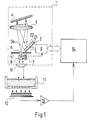
- the radiation source 1 of the spectrometer has been composed of light-emitting diodes, or LEDs.
- the radiation source 1 consists of a row of LEDs 2 which comprises a plurality of side-by-side LED semiconductor chips, or LED elements 21, 22, 23, ..., 26, which are all similar.
- the radiation source further comprises optical means for separating the desired wavelength range from the radiation produced by the LEDs, and means for maintaining the intensity of the radiation in the wavelength range constant or on desired level.
- Said optical means consist of optical pieces of equipment, such as lenses, mirrors, gratings, slits and beam dividers, the radiation produced by the LEDs being collected and dispersed to a spectrum with the aid of said means, and the radiation of the desired wavelength range being directed on an output slit or equivalent.
- the optical means in the spectrometer of Fig. 1 include a radiation-collecting lens 3, a reflecting grating 5 dispersing the radiation to a spectrum, and a stop 6 presenting an output slit 6.
- radiation-collecting component e.g. a concave mirror, and in place of the reflection grating one may use a transmission grating or a prism. These components may also be combined by using, for instance, a focussing reflector or transmission grating.
- the controllable radiation source 1 of the invention further comprises optical means and a detector 7 for observing and/or measuring the intensity of the outgoing radiation.
- the optical means employed in the spectrometer of Fig. 1 consist of a beam divider 8.
- the radiation source also comprises a driver and control means 9, to which the detector 7 has been connected.
- the driver and control means 9 is connected to the LED row 2, to each of its elements 21, 22, ..., 26. With the aid of the driver and control means 9, the desired LED element is selected.
- the desired wavelength range is directed on the output slit, this wavelength range depending on the location of the LED element 21, 22, ..., 26.
- Fig. 1 the output radiation passing through the exit slit 6 is rendered parallel with a lens 10, whereafter it is directed on the object of measurement, 11.
- a receiver 12 After the object of measurement, in the direction of propagation of the radiation, follows a receiver 12, in which capacity in measurements made on diffuse objects advantageously serves a wide-area radiometer.
- the electric signal from the receiver 12 is amplified in an amplifier 13 and fed to a calculation unit 14, and it is possibly displayed on a display provided in conjunction therewith.
- the driver and control unit 9 of the radiation source 1 may possibly also be controlled.
- At least the radiation source 1 is advantageous to devise at least the radiation source 1 to be an integral unit. It can be suitably shielded against ambience, for instance enclosed in a hermetically sealed housing, for improved reliability.
- the circuitry of the driver and control means 9 is presented in block diagram form in Fig. 3.
- the LED elements are connected to a selector means 16, such as a decoder, and this is connected to the calculating unit 14.
- the desired LED element, for instance the element 23, and the desired wavelength range of the output radiation from the radiation source are selected with the aid of the selector means 16.
- Part of the radiation obtained from the LED elements is picked up with the aid of the optical means 8 and carried to the detector 7.
- the detector 7 is connected with the controller 9a.
- the current control circuit 15 is governed by the controller 9a with the aid of the signal from the detector 7, in such manner that the output signal of the detector has constantly the desired magnitude, whereby the intensity of the output radiation also maintains the desired level.
- Fig. 2 illustrates the spectrum of the output radiation obtained by the procedure of the invention.
- the ordinates represent the radiation intensity I and the abscissae, the wavelength
- the radiation spectrum of a standard LED has the shape of a broad bell curve, L, Fig. 2A.
- the spectra of the radiation coming from, a radiation source 1 according to the invention are narrow bands of desired height, or ranges, S, Figs 2B-2E, within the range delimited by the bell curve L.
- the spectrometer of Fig. 1 and the radiation source therein employed operate in principle as follows.
- the driver and control means 9 selects and activates in the LED row 2 the first LED element 21.
- the radiation of the LED element is collected with the lens 3 and sent as a parallel beam to the reflection grating 4.
- the lens 3 further produces of the radiation reflected by the grating a spectrum on the stop 5. That part of the radiation (wavelength range ⁇ 1) passes through the output slit 6 which is determined by the location of the LED element 21 in the row and by the locations and dimensioning of the other optical means 3,4,6. From the lens 10) a parallel output radiation is obtained, striking the object of measurement 11.
- part of the output radiation is directed to strike the detector 7, and the signal representing the intensity that has been obtained is recorded with the driver and control means 9.
- the driver and control means adjusts the current going to the LED element 21 to have a value such that the signal obtained from the detector 7 rises to desired level, whereby the intensity of the output radiation also assumes the desired value, e.g. I0.
- the driver and control means 9 activates the LED element 22 and, after the output intensity has similarly been adjusted to required level, measurement takes place in the wavelength range ⁇ 2 (Fig. 2C).
- the driver and control means 9 activates all LED elements 21 ...
- the calculating unit 14 is electrically synchronized with the driver and control means 9 so that all results of measurement that have been recorded can be coordinated with the correct wavelength ranges ⁇ 1, ... ⁇ N .
- the optical means for collecting the radiation from the LED rows, for dispersing it to a spectrum and for directing the desired wavelength range on the output slit 6, comprising a lens 3 and a reflection grating 4 or equivalent.
- said optical means comprise a beam divider cube 17 and on the surface thereof a focussing transmission grating 18.
- the detector 7 for monitoring the intensity of the output radiation has been disposed in conjunction with the beam divider cube 17.
- the dividing interface 17a of the beam divider cube reflects to the detector 7 part of the radiation going through the beam divider cube to the output slit.
- In the capacity of output slit serves an optic fibre connector 19 to which an optic fibre 31 has been connected.
- the radiation source 1 with its LED row 2 is enclosed in a suitable housing 32.
- Fig. 5 depicts a compact spectrometer intended for reflection measurements and comprising both the transmitter of the radiation source and the receiver.
- the radiation source 1 is equivalent in its design with the radiation source of Fig. 4, and the same reference numerals are employed to indicate equivalent components.
- a receiver 33 In front of the radiation source 1, in the direction of propagation of the radiation, a receiver 33 has been disposed. This receiver consists of a beam divider 34 and a receiver detector 12. The output radiation is carried put from the device through an aperture 35.
- the object of measurement 36 which is a reflecting surface, is placed in front of the radiation beam coming from the spectrometer.
- the radiation reflected from the object of measurement 36 returns through the aperture 35 to the beam divider 34 of the receiver 33, from the dividing interface 34a of which the major part of the radiation is reflected to the receiver detector 12 and is detected.
- Both the radiation source 1 and the receiver 33 have in this case been integrated to constitute a single unit, which may be provided with a hermetically sealed housing 36 if required. In this way the reflection spectrometer can be made into a device usable in the field.
- the radiation from the spectrometer can be directed to strike the object of measurement 36 without any separate output optics, as has been set forth in the foregoing, or by using e.g. a standard lens optic system or a fibre-optic component.
- the LED row may be replaced with another type of radiation source row, as can be seen in Fig. 6.
- Fig. 6A presents, seen from the side, a LED row 2 comprising consecutively placed LED elements 21, 22, ..., 2N.
- the alternative radiation source row depicted in Fig. 6B comprises a number of LED elements or separate, encapsulated LEDs 21, 22 27, to each of them connected an optic fibre 41, 42, ..., 47 by its first end 41a, 42a, ..., 47a.
- the other ends 41b, 42b, ..., 47b of the optic fibres are arranged in a configuration such as is desired.
- the ends of the optic fibres are then close together and are thus equivalent e.g. to the LED row presented in the foregoing.
Abstract
Description
- The present invention relates to a method for controlling a radiation source which comprises a plurality of light-emitting diodes (LEDs); the method comprising a step of selectively driving one of said LEDs for producing output radiation within a selected wavelength range which is associated with the selected one of said LEDs.
- The present invention also relates to a controllable radiation source for producing output radiation within a selected wavelength range, comprising: a plurality of light-emitting diodes (LEDs); an output slit or equivalent; an optical dispersing element arranged in an optical path between said plurality of light-emitting diodes and said output slit, the optical dispersing element being adapted for receiving radiation and refracting the received radiation in a direction dependent on the wavelength of the received radiation; and a driver and control means for selectively driving one of said LEDs.
- A radiation source of the kind described is used for instance in spectrometers and photometers. In frequent cases the radiation source is the most significant factor limiting the capacity of performance and usability of an instrument. In apparatus meant to be used in industrial conditions, as radiation source have usually been employed thermal radiators, such as sources based on an incandescent filament, for instance. Their problem is, however, poor optical efficiency and consequent high heat dissipation, as well as poor vibration tolerance, short service, life and difficulty of modulation.
- In recent years the development of semiconductor technology has introduced on the market efficient lasers based on semiconductor junctions, and light-emitting diodes, or LEDs. They afford several advantages over traditional radiation sources: for instance, small size and low energy consumption, good reliability, long service life (even more than 10⁸ hours), high operating speed, easy connection to optic fibres. Furthermore, they can be electrically modulated with ease. Semiconductor radiation sources are nowadays available for the wavelength range about 400 nm to over 10 µm; admittedly, though, for operation at room temperature only up to about 3200 nm. The said range is usable in quantitative and qualitative analysis of most substances.
- Semiconductor lasers are nearly ideal radiation sources for spectrometers in view of their narrow spectrum. However, high price and poor stability are their problems. It is also a fact that the selection of standard wavelengths is scanty, particularly in the near IR range. LEDs enable, owing to their wider radiation spectrum, a considerably wider wavelength range to be covered, and they are also lower in price. The spectral radiance of LEDs is on the same order as that of most thermic radiation sources, or higher.
- The radiations spectrum of LEDs is mostly too wide to allow them to be used as such in spectroscopic measurements. Moreover, the shape of the radiation spectrum, the peak wavelength and the radiant power change powerfully with changing temperature and driving current, and with time.
- In spectrometer designs of prior art based on the use of LED sources, the measuring band is separated from the LEDs, usually, with the aid of separate filters, or the LED is used without filtering, in which case the resolution will also be poor. The variation of radiation intensity has most often been compensated for, either by mere electric compensation or by maintaining constant temperature of the LED, which has lead to a demanding and expensive mechanical design.Owing to the high price and difficult manipulation of the filters (e.g. miniaturizing, cutting), the number of wavelength bands in such pieces of apparatus is usually small (2 to 10).
- A method as described in the preamble of
claim 1 and a radiation source as described in the preamble of claim 3 are disclosed in European patent application 0 110 201. This prior apparatus, however, comprises quasi-monochromatic radiation elements which must be carefully positioned along a Rowland circle. Each of said quasi-monochromatic radiation elements produces radiation in only one of the selectable wavelength ranges, so that all the radiation elements must be different from each other.
A further drawback of this prior apparatus is that it needs a rather complex configuration wherein the whole of said radiation elements is moved along said Rowland circle and/or the optical dispersing element is rotated. - The object of the present invention is to eliminate, among others, the drawbacks inventioned above and to provide a novel procedure for controlling a radiation source, and a controllable radiation source. This is realized with the aid of the characteristic features of the invention stated un the claims hereto attached.
- With the aid of the invention following advantages are gained, among others. On the basis of the procedure of the invention a controllable radiation source can be realized which is simple as to its construction and contains no moving parts. Furthermore, the radiation source can be realized in a design with small external dimensions. Good wavelength resolution can be achieved in spite of small size. The wavelength resolution is determined, in the first place, be the size of the LED elements (typically only 300 µm by 300 µm) and by the angular dispersion and dimensions of the optics which disperse the radiation into a spectrum. The number of measuring channels in the spectrometer in which the procedure of the invention is applied may with ease be increased to be several dozen. The amount of required electronic control and driver apparatus is not necessarily dependent on the number of LEDs. According to the procedure, the intensity of the wavelength bands is also stabilized. The changes of the spectrum of the LEDs and of the total radiant power will then have no influence and the output intensity of the radiation source. According to the procedure, the wavelengths of the radiation source may be electrically selected. The modulation frequency can be made very high if required (e.g. less than 1 µs per LED).It is possible in connection with the controllable radiation source of the invention to use for detector a single-channel radiometer, in which advantageously one single detector element is used. The procedure, and the radiation source applying it, can be used in the visible light and IR radiation ranges.
- The invention may be applied in the transmitter part of the spectrometer. In certain applications it is also possible to integrate the whole spectrometer to be one single component, which may be hermetically encapsulated. A reliable and stable spectrometer, and one which is usable in field work, is obtained with the aid of such integration.
- Significant advantages are gainable with the aid of the procedure of the invention, and of the radiation source employing it, in reflection or transmission measurements on diffuse objects, compared with the multiple detector technique, which has become commonly used in recent years. In multiple element spectrometers the diffuse radiation has to be collected on small-sized detector elements through a narrow entrance slit, whereby high optical collection losses are incurred. In the controllable radiation source of the invention, the optical collection losses can be minimized by using for detector the single-channel radiometer mentioned above, which has a large-sized detector element and, at the same time, also a wide collection angle.
- The invention is described in detail in the following with the aid of the attached drawings, wherein:-
- Fig. 1 presents schematically a spectrometer in which the invention is applied;
- Fig. 2 presents by way of example the radiation spectrum of a LED and the radiation spectrum achievable with the aid of the invention;
- Fig. 3 presents in the form of a block diagram a LED row and its driver and control means;
- Fig. 4 presents a radiation source according to the invention in which an optic fibre is utilized; and
- Fig. 5 presents schematically a reflection spectrometer in which the invention is applied,
- Fig. 6 presents a radiation source row, Fig. 6B, by which a LED row, Fig. 6A, may be replaced.
- In the procedure of the invention the radiation source is realized with a LED array composed of semiconductor chips, or LED elements, or equivalent. From the radiation of the LED elements a wavelength range depending on the location of the LED element in said array is separated with an optical means dispersing radiation to a spectrum, and the intensity of this wavelength range, or output radiation, is controlled or maintained constant by observing its intensity and with its aid regulating the current passing through the respective LED element. The desired wavelength range may then be selected electrically by activating the respective element in the LED array.
- In the spectrometer of Fig. 1 the procedure of the invention is applied. The
radiation source 1 of the spectrometer has been composed of light-emitting diodes, or LEDs. Specifically, theradiation source 1 consists of a row ofLEDs 2 which comprises a plurality of side-by-side LED semiconductor chips, orLED elements stop 6 presenting anoutput slit 6. It is equally possible to use for radiation-collecting component e.g. a concave mirror, and in place of the reflection grating one may use a transmission grating or a prism. These components may also be combined by using, for instance, a focussing reflector or transmission grating. - The
controllable radiation source 1 of the invention further comprises optical means and adetector 7 for observing and/or measuring the intensity of the outgoing radiation. The optical means employed in the spectrometer of Fig. 1 consist of abeam divider 8. The radiation source also comprises a driver and control means 9, to which thedetector 7 has been connected. The driver and control means 9 is connected to theLED row 2, to each of itselements LED element detector 7, the current flowing through the respective LED element and producing the radiation in question being regulated in accordance with the intensity data supplied by the detector and in such manner that the radiation intensity of that wavelength range, and thus the intensity of the output radiation, is constant. - Also other optical means may further be attached to the
radiation source 1. In Fig. 1, the output radiation passing through the exit slit 6 is rendered parallel with alens 10, whereafter it is directed on the object of measurement, 11. After the object of measurement, in the direction of propagation of the radiation, follows areceiver 12, in which capacity in measurements made on diffuse objects advantageously serves a wide-area radiometer. The electric signal from thereceiver 12 is amplified in anamplifier 13 and fed to acalculation unit 14, and it is possibly displayed on a display provided in conjunction therewith. With the calculatingunit 14, or by controls on a panel provided in conjunction therewith, the driver andcontrol unit 9 of theradiation source 1 may possibly also be controlled. - For reflection and/or transmission measurements, it is advantageous to devise at least the
radiation source 1 to be an integral unit. It can be suitably shielded against ambience, for instance enclosed in a hermetically sealed housing, for improved reliability. - The circuitry of the driver and control means 9 is presented in block diagram form in Fig. 3. The
LED elements integer current control circuit 15 to avoltage source 30. The LED elements are connected to a selector means 16, such as a decoder, and this is connected to the calculatingunit 14. The desired LED element, for instance theelement 23, and the desired wavelength range of the output radiation from the radiation source are selected with the aid of the selector means 16. Part of the radiation obtained from the LED elements is picked up with the aid of theoptical means 8 and carried to thedetector 7. Thedetector 7 is connected with thecontroller 9a. Thecurrent control circuit 15 is governed by thecontroller 9a with the aid of the signal from thedetector 7, in such manner that the output signal of the detector has constantly the desired magnitude, whereby the intensity of the output radiation also maintains the desired level. - Fig. 2 illustrates the spectrum of the output radiation obtained by the procedure of the invention. In the rectangular coordinates, the ordinates represent the radiation intensity I and the abscissae, the wavelength The radiation spectrum of a standard LED has the shape of a broad bell curve, L, Fig. 2A. The spectra of the radiation coming from, a
radiation source 1 according to the invention are narrow bands of desired height, or ranges, S, Figs 2B-2E, within the range delimited by the bell curve L. - The spectrometer of Fig. 1 and the radiation source therein employed operate in principle as follows. The driver and control means 9 selects and activates in the
LED row 2 thefirst LED element 21. The radiation of the LED element is collected with the lens 3 and sent as a parallel beam to the reflection grating 4. The lens 3 further produces of the radiation reflected by the grating a spectrum on the stop 5. That part of the radiation (wavelength range Δλ₁) passes through the output slit 6 which is determined by the location of theLED element 21 in the row and by the locations and dimensioning of the otheroptical means 3,4,6. From the lens 10) a parallel output radiation is obtained, striking the object ofmeasurement 11. - Through the
optical means 8, part of the output radiation is directed to strike thedetector 7, and the signal representing the intensity that has been obtained is recorded with the driver and control means 9. The driver and control means adjusts the current going to theLED element 21 to have a value such that the signal obtained from thedetector 7 rises to desired level, whereby the intensity of the output radiation also assumes the desired value, e.g. I₀. Hereafter the actual measurement takes place in the wavelength range Δλ₁ (Fig. 2B) and the result is recorded in the calculatingunit 14. Next, the driver and control means 9 activates theLED element 22 and, after the output intensity has similarly been adjusted to required level, measurement takes place in the wavelength range Δλ₂ (Fig. 2C). The driver and control means 9 activates allLED elements 21 ... 2N in succession and measurements are similarly carried out in the wavelength ranges ..., ΔλN (Fig, 2E), whereafter the driver and control means 9 activates again theLED element 21, and so on. The calculatingunit 14 is electrically synchronized with the driver and control means 9 so that all results of measurement that have been recorded can be coordinated with the correct wavelength ranges Δλ₁, ... ΔλN. - In the foregoing in the spectrometer of Fig. 1 the optical means for collecting the radiation from the LED rows, for dispersing it to a spectrum and for directing the desired wavelength range on the
output slit 6, comprising a lens 3 and a reflection grating 4 or equivalent. In the radiation source of Fig. 4, said optical means comprise abeam divider cube 17 and on the surface thereof a focussing transmission grating 18. In this case thedetector 7 for monitoring the intensity of the output radiation has been disposed in conjunction with thebeam divider cube 17. The dividinginterface 17a of the beam divider cube reflects to thedetector 7 part of the radiation going through the beam divider cube to the output slit. In the capacity of output slit serves anoptic fibre connector 19 to which anoptic fibre 31 has been connected. Theradiation source 1 with itsLED row 2 is enclosed in asuitable housing 32. - Fig. 5 depicts a compact spectrometer intended for reflection measurements and comprising both the transmitter of the radiation source and the receiver. The
radiation source 1 is equivalent in its design with the radiation source of Fig. 4, and the same reference numerals are employed to indicate equivalent components. In front of theradiation source 1, in the direction of propagation of the radiation, areceiver 33 has been disposed. This receiver consists of abeam divider 34 and areceiver detector 12. The output radiation is carried put from the device through anaperture 35. The object ofmeasurement 36, which is a reflecting surface, is placed in front of the radiation beam coming from the spectrometer. The radiation reflected from the object ofmeasurement 36 returns through theaperture 35 to thebeam divider 34 of thereceiver 33, from the dividinginterface 34a of which the major part of the radiation is reflected to thereceiver detector 12 and is detected. Both theradiation source 1 and thereceiver 33 have in this case been integrated to constitute a single unit, which may be provided with a hermetically sealedhousing 36 if required. In this way the reflection spectrometer can be made into a device usable in the field. The radiation from the spectrometer can be directed to strike the object ofmeasurement 36 without any separate output optics, as has been set forth in the foregoing, or by using e.g. a standard lens optic system or a fibre-optic component. - The LED row may be replaced with another type of radiation source row, as can be seen in Fig. 6. Fig. 6A presents, seen from the side, a
LED row 2 comprising consecutively placedLED elements LEDs optic fibre first end - It should be noted that although the invention has been presented in the foregoing in the first place only with the aid of one measuring apparatus, it is obvious that the procedure for controlling a radiation source, and the controlled radiation source, can be employed in numerous other applications as well in which a stable, or easy to control, radiation source is needed which produces radiation within a given wavelength range in a plurality of alternatingly active, and if need be narrow, wavelength bands. Moreover, in the embodiment examples of the invention presented in the foregoing a LED row or equivalent is employed, but it is also possible to use in its stead a LED matrix or any other equivalent LED array.
Claims (10)
- A method for controlling a radiation source (1) which comprises a plurality of light-emitting diodes or LEDs (21, 22, 23, ... 26);
the method comprising a step of selectively driving one of said LEDs for producing output radiation within a selected wavelength range (Δλ₁, Δλ₂, Δλ₃, ...);
characterized by the steps of separating said selected wavelength range from a relatively wide wavelength range of radiation emitted by said one LED, and directing this separated wavelength range to an output slit (6) or equivalent, said separating and directing being performed by means of optical dispersing means (3, 4, 5), wherein said separated wavelength range depends on the position of said LED with respect to the optical dispersing means (3, 4, 5);
measuring the intensity of the radiation in said selected wavelength range or of the output radiation, and regulating the current passing through said one driven LED in response to the measured intensity such that this measured intensity is controlled or maintained constant. - Method according to claim 1, characterized in that the wavelength ranges (Δλ₁, Δλ₂, Δλ₃, ...) of the output radiation are selected electrically by activating a suitable LED element (21, 22, 23, ... 26) of said plurality of LED's.
- A controllable radiation source (1) for producing output radiation within a selected wavelength range (Δλ₁, Δλ₂, Δλ₃, ...), comprising:
a plurality of light-emitting diodes or LEDs (21, 22, 23, ... 26); an output slit (6) or equivalent;
an optical dispersing element (3, 4, 5) arranged in an optical path between said plurality of light-emitting diodes and said output slit, the optical dispersing element being adapted for receiving radiation and refracting the received radiation in a direction dependent on the wavelength of the received radiation; and a driver and control means (9) for selectively driving one of said LEDs;
characterized in:
that the light-emitting diodes are similar to each other and emit radiation in a relatively wide wavelength range from which the selected wave length range is determined by the position of a separately driven LED in respect to the optical dispersing element ;
that optical means (8) are arranged such as to direct part of the output radiation, or of the radiation which is refracted by the optical dispersing element towards the output slit, towards a radiation intensity detector (7) for measuring the intensity of said radiation within said selected wavelength range; and
that the driver and control means (9) is adapted to drive the selected LED in response to the intensity detected by the radiation intensity detector such that the intensity of said radiation within said selected wavelength range as detected by the radiation intensity detector (7) is controlled or maintained at a desired value (I₀). - Radiation source according to claim 3, characterized in that the LED elements (21, 22, 23, ..., 26) are arranged in an LED array (2,2′) and are connected together and connected with a current control circuit (15) and a selector means (16) with the aid of which the desired LED element (e.g. 23) and the desired wavelength range (Δλ₃) of the output radiation of the radiation source are selected and which current control circuit (15) is governed by a controller (9a) with the aid of the signal from the detector (7) in such manner that the intensity (I₀) of the output radiation continuously maintains the same value.
- Radiation source according to claim 3 or 4, characterized in that said optical means for receiving and dispersing the radiation produced by the LEDs and for directing the desired wavelength range on the output slit (6) comprise a focussing reflection or transmission grating.
- Radiation source according to claim 3 or 4, characterized in that said optical means for receiving and dispersing the radiation produced by the LEDs and for directing the desired wavelength range on the output slit (6) and on the detector (7) comprise a beam divider cube (17) and on the surface thereof a transmission grating (18).
- Radiation source according to claim 6, characterized in that the detector (7) for observing the intensity of the output radiation has been disposed in conjunction with the beam divider cube (17) so that the beam divider cube also serves as an optical means associated with the detector.
- Radiation source according to any one of the preceding claims 3-7 for performing reflection and/or transmission measurement, characterized in that the radiation source (1) has been formed to be an integral unit (32).
- Means according to any one of the preceding claims 3-7 for performing reflection measurements, characterized in that the radiation source (1) is integrated with a receiver (33) to constitute an integrated unit for performing reflection measurements, which unit is advantageously provided with a hermetically sealed housing (37).
- Radiation source according to any one of the preceding claims 3-7, characterized in that the LED array (2′) consists of a plurality of LED elements or separate encapsulated LEDs (21, 22, ..., 27,Fig. 6B) to each of which is connected an optic fibre (41, 42, ..., 47) by its first end (41a, 42a, ..., 47a) and the second ends (41b, 42b, ..., 47b) have been arranged in a desired configuration.
Applications Claiming Priority (3)
| Application Number | Priority Date | Filing Date | Title |
|---|---|---|---|
| FI872824 | 1987-06-25 | ||
| FI872824A FI77736C (en) | 1987-06-25 | 1987-06-25 | FOERFARANDE FOER REGLERING AV STRAOLKAELLA OCH REGLERBAR STRAOLKAELLA. |
| PCT/FI1988/000103 WO1988010462A1 (en) | 1987-06-25 | 1988-06-23 | Procedure for controlling a radiation source and controllable radiation source |
Publications (2)
| Publication Number | Publication Date |
|---|---|
| EP0366696A1 EP0366696A1 (en) | 1990-05-09 |
| EP0366696B1 true EP0366696B1 (en) | 1994-11-23 |
Family
ID=8524727
Family Applications (1)
| Application Number | Title | Priority Date | Filing Date |
|---|---|---|---|
| EP88905853A Expired - Lifetime EP0366696B1 (en) | 1987-06-25 | 1988-06-23 | Procedure for controlling a radiation source and controllable radiation source |
Country Status (5)
| Country | Link |
|---|---|
| US (1) | US5029245A (en) |
| EP (1) | EP0366696B1 (en) |
| DE (1) | DE3852176T2 (en) |
| FI (1) | FI77736C (en) |
| WO (1) | WO1988010462A1 (en) |
Families Citing this family (79)
| Publication number | Priority date | Publication date | Assignee | Title |
|---|---|---|---|---|
| US5369286A (en) * | 1989-05-26 | 1994-11-29 | Ann F. Koo | Method and apparatus for measuring stress in a film applied to surface of a workpiece |
| GB8913800D0 (en) * | 1989-06-15 | 1989-08-02 | Secr Defence | Colour monitoring |
| JPH03269681A (en) * | 1990-03-19 | 1991-12-02 | Sharp Corp | Picture recognizing device |
| WO1994015183A1 (en) * | 1991-06-28 | 1994-07-07 | Valtion Teknillinen Tutkimuskeskus | Radiation source |
| US5523582A (en) * | 1992-04-30 | 1996-06-04 | Ann F. Koo | Method and apparatus for measuring the curvature of wafers with a laser source selecting device |
| US5477322A (en) * | 1994-10-13 | 1995-12-19 | Nirsystems Incorporated | Spectrophotometer with light source in the form of a light emitting diode array |
| US5758644A (en) * | 1995-06-07 | 1998-06-02 | Masimo Corporation | Manual and automatic probe calibration |
| IT1280954B1 (en) * | 1995-10-05 | 1998-02-11 | Sorin Biomedica Cardio Spa | PROCEDURE AND SYSTEM FOR DETECTING CHEMICAL-PHYSICAL PARAMETERS. |
| FI103074B1 (en) * | 1996-07-17 | 1999-04-15 | Valtion Teknillinen | spectrometer |
| EP1610115A3 (en) * | 1997-05-23 | 2010-03-03 | Becton, Dickinson and Company | Automated microbiological testing apparatus and methods therefor |
| ES2251085T3 (en) * | 1997-05-23 | 2006-04-16 | Becton Dickinson And Company | APPARATUS AND AUTOMATED MICROBIOLOGICAL TEST METHOD. |
| JP3971844B2 (en) | 1998-05-13 | 2007-09-05 | 株式会社キーエンス | Optical device, photoelectric switch, fiber type photoelectric switch, and color identification sensor |
| US6483112B1 (en) | 1998-07-14 | 2002-11-19 | E. Neil Lewis | High-throughput infrared spectroscopy |
| EP1095246B1 (en) * | 1998-07-14 | 2010-06-23 | The Government of the United States of America, represented by the Secretary, Department of Health and Human Services | High-throughput infrared spectroscopy |
| US6310337B1 (en) * | 1998-08-13 | 2001-10-30 | Joseph M. Chiapperi | Method of preselecting flashlamp voltages for assays |
| USRE41912E1 (en) | 1998-10-15 | 2010-11-02 | Masimo Corporation | Reusable pulse oximeter probe and disposable bandage apparatus |
| US6721585B1 (en) | 1998-10-15 | 2004-04-13 | Sensidyne, Inc. | Universal modular pulse oximeter probe for use with reusable and disposable patient attachment devices |
| DE29901464U1 (en) * | 1999-01-28 | 2000-07-06 | J & M Analytische Mess & Regeltechnik Gmbh | Combination light source and analysis system using the same |
| US6690464B1 (en) * | 1999-02-19 | 2004-02-10 | Spectral Dimensions, Inc. | High-volume on-line spectroscopic composition testing of manufactured pharmaceutical dosage units |
| US6403947B1 (en) | 1999-03-18 | 2002-06-11 | Cambridge Research & Instrumentation Inc. | High-efficiency multiple probe imaging system |
| US7123844B2 (en) * | 1999-04-06 | 2006-10-17 | Myrick Michael L | Optical computational system |
| US6529276B1 (en) | 1999-04-06 | 2003-03-04 | University Of South Carolina | Optical computational system |
| US6259430B1 (en) | 1999-06-25 | 2001-07-10 | Sarnoff Corporation | Color display |
| US20070195392A1 (en) * | 1999-07-08 | 2007-08-23 | Jds Uniphase Corporation | Adhesive Chromagram And Method Of Forming Thereof |
| US7667895B2 (en) * | 1999-07-08 | 2010-02-23 | Jds Uniphase Corporation | Patterned structures with optically variable effects |
| US6761959B1 (en) * | 1999-07-08 | 2004-07-13 | Flex Products, Inc. | Diffractive surfaces with color shifting backgrounds |
| US6750964B2 (en) * | 1999-08-06 | 2004-06-15 | Cambridge Research And Instrumentation, Inc. | Spectral imaging methods and systems |
| WO2001011343A1 (en) | 1999-08-06 | 2001-02-15 | Cambridge Research & Instrumentation Inc. | Spectral imaging system |
| EP1210584A1 (en) * | 1999-08-19 | 2002-06-05 | Washington State University Research Foundation | Methods for determining the physiological state of a plant |
| EP1252027A1 (en) * | 2000-01-21 | 2002-10-30 | Flex Products, Inc. | Optically variable security devices |
| AU2001238492A1 (en) * | 2000-02-18 | 2001-08-27 | Spectral Dimensions, Inc. | Multi-source spectrometry |
| US7138156B1 (en) | 2000-09-26 | 2006-11-21 | Myrick Michael L | Filter design algorithm for multi-variate optical computing |
| JP4685229B2 (en) * | 2000-10-31 | 2011-05-18 | オリンパス株式会社 | Laser microscope |
| US6689999B2 (en) * | 2001-06-01 | 2004-02-10 | Schott-Fostec, Llc | Illumination apparatus utilizing light emitting diodes |
| US6930773B2 (en) * | 2001-08-23 | 2005-08-16 | Cambridge Research And Instrumentation, Inc. | Spectral imaging |
| US6825930B2 (en) * | 2002-06-04 | 2004-11-30 | Cambridge Research And Instrumentation, Inc. | Multispectral imaging system |
| US7251587B2 (en) * | 2002-08-12 | 2007-07-31 | System To Asic, Inc. | Flexible scanning and sensing platform |
| US20040188594A1 (en) * | 2003-05-01 | 2004-09-30 | Brown Steven W. | Spectrally tunable solid-state light source |
| US7500950B2 (en) | 2003-07-25 | 2009-03-10 | Masimo Corporation | Multipurpose sensor port |
| US20050030192A1 (en) * | 2003-08-08 | 2005-02-10 | Weaver James T. | Power supply for LED airfield lighting |
| US7321791B2 (en) * | 2003-09-23 | 2008-01-22 | Cambridge Research And Instrumentation, Inc. | Spectral imaging of deep tissue |
| US8634607B2 (en) * | 2003-09-23 | 2014-01-21 | Cambridge Research & Instrumentation, Inc. | Spectral imaging of biological samples |
| US7324569B2 (en) * | 2004-09-29 | 2008-01-29 | Axsun Technologies, Inc. | Method and system for spectral stitching of tunable semiconductor sources |
| WO2006081547A1 (en) | 2005-01-27 | 2006-08-03 | Cambridge Research And Instrumentation, Inc. | Classifying image features |
| US7499165B2 (en) * | 2005-03-15 | 2009-03-03 | Electronic Design To Market, Inc. | System of measuring light transmission and/or reflection |
| DE102005022175A1 (en) * | 2005-05-13 | 2006-12-21 | Carl Zeiss Jena Gmbh | Multispectral lighting unit |
| US7279678B2 (en) * | 2005-08-15 | 2007-10-09 | Schlumber Technology Corporation | Method and apparatus for composition analysis in a logging environment |
| CA2564764C (en) * | 2005-10-25 | 2014-05-13 | Jds Uniphase Corporation | Patterned optical structures with enhanced security feature |
| US8345234B2 (en) * | 2005-11-28 | 2013-01-01 | Halliburton Energy Services, Inc. | Self calibration methods for optical analysis system |
| US10188348B2 (en) | 2006-06-05 | 2019-01-29 | Masimo Corporation | Parameter upgrade system |
| WO2008002903A2 (en) | 2006-06-26 | 2008-01-03 | University Of South Carolina | Data validation and classification in optical analysis systems |
| US7880626B2 (en) | 2006-10-12 | 2011-02-01 | Masimo Corporation | System and method for monitoring the life of a physiological sensor |
| US8255026B1 (en) | 2006-10-12 | 2012-08-28 | Masimo Corporation, Inc. | Patient monitor capable of monitoring the quality of attached probes and accessories |
| US9182282B2 (en) * | 2006-11-02 | 2015-11-10 | Halliburton Energy Services, Inc. | Multi-analyte optical computing system |
| US7651268B2 (en) * | 2007-02-23 | 2010-01-26 | Cao Group, Inc. | Method and testing equipment for LEDs and laser diodes |
| US8212216B2 (en) * | 2007-03-30 | 2012-07-03 | Halliburton Energy Services, Inc. | In-line process measurement systems and methods |
| US8184295B2 (en) * | 2007-03-30 | 2012-05-22 | Halliburton Energy Services, Inc. | Tablet analysis and measurement system |
| WO2008121684A1 (en) * | 2007-03-30 | 2008-10-09 | University Of South Carolina | Novel multi-analyte optical computing system |
| EP2245467B1 (en) | 2008-02-05 | 2022-04-06 | Pocared Diagnostics Ltd. | System for conducting the identification of bacteria in biological samples |
| US8212213B2 (en) * | 2008-04-07 | 2012-07-03 | Halliburton Energy Services, Inc. | Chemically-selective detector and methods relating thereto |
| US8406859B2 (en) | 2008-08-10 | 2013-03-26 | Board Of Regents, The University Of Texas System | Digital light processing hyperspectral imaging apparatus |
| US8101906B2 (en) | 2008-10-08 | 2012-01-24 | Applied Materials, Inc. | Method and apparatus for calibrating optical path degradation useful for decoupled plasma nitridation chambers |
| US8309897B2 (en) * | 2009-02-06 | 2012-11-13 | Pocared Diagnostics Ltd. | Optical measurement arrangement |
| US8571619B2 (en) | 2009-05-20 | 2013-10-29 | Masimo Corporation | Hemoglobin display and patient treatment |
| US10288632B2 (en) | 2009-09-21 | 2019-05-14 | Pocared Diagnostics Ltd. | System for conducting the identification of bacteria in biological samples |
| DE102009046831B4 (en) * | 2009-11-18 | 2015-02-12 | Fraunhofer-Gesellschaft zur Förderung der angewandten Forschung e.V. | A radiation generating device for generating an electromagnetic radiation with an adjustable spectral composition and method for producing the same |
| JP5796275B2 (en) * | 2010-06-02 | 2015-10-21 | セイコーエプソン株式会社 | Spectrometer |
| JP5254308B2 (en) * | 2010-12-27 | 2013-08-07 | 東京エレクトロン株式会社 | Liquid processing apparatus, liquid processing method, and recording medium storing program for executing liquid processing method |
| WO2012170963A1 (en) * | 2011-06-08 | 2012-12-13 | Digital Light Innovations | System and method for hyperspectral imaging |
| US20130148107A1 (en) * | 2011-12-07 | 2013-06-13 | Honeywell Asca Inc. | Multi-source sensor for online characterization of web products and related system and method |
| JP5842652B2 (en) * | 2012-02-08 | 2016-01-13 | 株式会社島津製作所 | Tunable monochromatic light source |
| US8859969B2 (en) | 2012-03-27 | 2014-10-14 | Innovative Science Tools, Inc. | Optical analyzer for identification of materials using reflectance spectroscopy |
| US9297749B2 (en) | 2012-03-27 | 2016-03-29 | Innovative Science Tools, Inc. | Optical analyzer for identification of materials using transmission spectroscopy |
| EP2929321B1 (en) | 2012-12-07 | 2019-06-05 | Sp3H | Onboard device and method for analyzing a fluid in a heat engine |
| WO2014093463A1 (en) | 2012-12-11 | 2014-06-19 | Pocared Diagnostics Ltd. | Optics cup with curved bottom |
| US9182278B2 (en) * | 2013-03-14 | 2015-11-10 | Sciaps, Inc. | Wide spectral range spectrometer |
| JP6774174B2 (en) * | 2015-10-08 | 2020-10-21 | 株式会社キーエンス | Photoelectric switch |
| WO2018020535A1 (en) * | 2016-07-25 | 2018-02-01 | 株式会社島津製作所 | Photometer |
| CN112611456A (en) * | 2019-09-18 | 2021-04-06 | 深圳市中光工业技术研究院 | Spectrometer |
Family Cites Families (11)
| Publication number | Priority date | Publication date | Assignee | Title |
|---|---|---|---|---|
| US4022531A (en) * | 1973-10-17 | 1977-05-10 | U.S. Philips Corporation | Monochromator |
| JPS5182630A (en) * | 1975-01-16 | 1976-07-20 | Minolta Camera Kk | |
| JPS54143109A (en) * | 1978-04-28 | 1979-11-08 | Hitachi Ltd | Optical information device |
| US4455562A (en) * | 1981-08-14 | 1984-06-19 | Pitney Bowes Inc. | Control of a light emitting diode array |
| US4443695A (en) * | 1980-01-25 | 1984-04-17 | Canon Kabushiki Kaisha | Apparatus for controlling the quantity of light |
| ES8101334A1 (en) * | 1980-06-04 | 1980-12-16 | Standard Electrica Sa | A protection procedure for the luminous source of optical transmitters (Machine-translation by Google Translate, not legally binding) |
| HU186069B (en) * | 1982-06-09 | 1985-05-28 | Koezponti Elelmiszeripari | Spectrophotometer operating on discrete wave-lengths |
| US4449821A (en) * | 1982-07-14 | 1984-05-22 | E. I. Du Pont De Nemours And Company | Process colorimeter |
| HU187188B (en) * | 1982-11-25 | 1985-11-28 | Koezponti Elelmiszeripari | Device for generating radiation of controllable spectral structure |
| NL8400380A (en) * | 1984-02-07 | 1985-09-02 | Optische Ind De Oude Delft Nv | DEVICE FOR DETECTING COLOR DIFFERENCES. |
| US4790654A (en) * | 1987-07-17 | 1988-12-13 | Trw Inc. | Spectral filter |
-
1987
- 1987-06-25 FI FI872824A patent/FI77736C/en not_active IP Right Cessation
-
1988
- 1988-06-23 US US07/457,694 patent/US5029245A/en not_active Expired - Lifetime
- 1988-06-23 DE DE3852176T patent/DE3852176T2/en not_active Expired - Fee Related
- 1988-06-23 WO PCT/FI1988/000103 patent/WO1988010462A1/en active IP Right Grant
- 1988-06-23 EP EP88905853A patent/EP0366696B1/en not_active Expired - Lifetime
Also Published As
| Publication number | Publication date |
|---|---|
| WO1988010462A1 (en) | 1988-12-29 |
| DE3852176T2 (en) | 1995-06-22 |
| DE3852176D1 (en) | 1995-01-05 |
| FI77736B (en) | 1988-12-30 |
| FI77736C (en) | 1989-04-10 |
| US5029245A (en) | 1991-07-02 |
| EP0366696A1 (en) | 1990-05-09 |
| FI872824A0 (en) | 1987-06-25 |
Similar Documents
| Publication | Publication Date | Title |
|---|---|---|
| EP0366696B1 (en) | Procedure for controlling a radiation source and controllable radiation source | |
| CA2261139C (en) | Spectrometer | |
| US4060327A (en) | Wide band grating spectrometer | |
| US5818586A (en) | Miniaturized fabry-perot spectrometer for optical analysis | |
| US5475221A (en) | Optical spectrometer using light emitting diode array | |
| US6272269B1 (en) | Optical fiber/waveguide illumination system | |
| EP1399694B1 (en) | Led luminaire with light sensor configurations for optical feedback | |
| US6270244B1 (en) | Fiber optic illumination system having diffraction grating wavelength selector | |
| EP0413939B1 (en) | Improved grating spectrometer | |
| US20100007877A1 (en) | Narrow-band spectrometric Measurements | |
| WO1995010759A1 (en) | Spectral wavelength discrimination system and method for using | |
| CN1372635A (en) | Improvements in, or relating to, infra-red detection | |
| EP1111333A1 (en) | Light source device, spectroscope comprising the light source device, and film thickness sensor | |
| US4722606A (en) | Analytical photometer, in particular multi-channel, applied to a centrifugal system adapted to perform practically simultaneous determination of the presence of different substances in a certain number of samples | |
| Bortolot | Improved OSL excitation with fiberoptics and focused lamps | |
| CN113884199A (en) | Calibration device and calibration method for MEMS Fabry-Perot cavity chip | |
| EP0063126B1 (en) | Optical transmission systems | |
| Keranen et al. | Semiconductor emitter based 32-channel spectrophotometer module for real-time process measurements | |
| Malinen et al. | Thirty-two-channel LED array spectrometer module with compact optomechanical construction | |
| WO2003087786A1 (en) | Method and apparatus for gas detection | |
| FI89631C (en) | STRAOLKAELLA OCH EXCITATIONSANORDNING FOER DEN | |
| CN108709163A (en) | A kind of light source output Wavelength tuning device | |
| WO1994015183A1 (en) | Radiation source | |
| JPS58165022A (en) | Spectrophotometer | |
| Malinen et al. | LED-based spectrometer modules for handheld sensors and online process monitoring |
Legal Events
| Date | Code | Title | Description |
|---|---|---|---|
| PUAI | Public reference made under article 153(3) epc to a published international application that has entered the european phase |
Free format text: ORIGINAL CODE: 0009012 |
|
| 17P | Request for examination filed |
Effective date: 19891222 |
|
| AK | Designated contracting states |
Kind code of ref document: A1 Designated state(s): BE DE FR GB IT NL SE |
|
| 17Q | First examination report despatched |
Effective date: 19930121 |
|
| GRAA | (expected) grant |
Free format text: ORIGINAL CODE: 0009210 |
|
| AK | Designated contracting states |
Kind code of ref document: B1 Designated state(s): BE DE FR GB IT NL SE |
|
| ITF | It: translation for a ep patent filed |
Owner name: BARZANO' E ZANARDO ROMA S.P.A. |
|
| REF | Corresponds to: |
Ref document number: 3852176 Country of ref document: DE Date of ref document: 19950105 |
|
| ET | Fr: translation filed | ||
| EAL | Se: european patent in force in sweden |
Ref document number: 88905853.3 |
|
| PLBE | No opposition filed within time limit |
Free format text: ORIGINAL CODE: 0009261 |
|
| STAA | Information on the status of an ep patent application or granted ep patent |
Free format text: STATUS: NO OPPOSITION FILED WITHIN TIME LIMIT |
|
| 26N | No opposition filed | ||
| REG | Reference to a national code |
Ref country code: GB Ref legal event code: IF02 |
|
| PGFP | Annual fee paid to national office [announced via postgrant information from national office to epo] |
Ref country code: FR Payment date: 20050512 Year of fee payment: 18 |
|
| PGFP | Annual fee paid to national office [announced via postgrant information from national office to epo] |
Ref country code: GB Payment date: 20050516 Year of fee payment: 18 |
|
| PGFP | Annual fee paid to national office [announced via postgrant information from national office to epo] |
Ref country code: NL Payment date: 20050517 Year of fee payment: 18 |
|
| PGFP | Annual fee paid to national office [announced via postgrant information from national office to epo] |
Ref country code: SE Payment date: 20050519 Year of fee payment: 18 |
|
| PGFP | Annual fee paid to national office [announced via postgrant information from national office to epo] |
Ref country code: DE Payment date: 20050520 Year of fee payment: 18 |
|
| PGFP | Annual fee paid to national office [announced via postgrant information from national office to epo] |
Ref country code: BE Payment date: 20050606 Year of fee payment: 18 |
|
| PG25 | Lapsed in a contracting state [announced via postgrant information from national office to epo] |
Ref country code: GB Free format text: LAPSE BECAUSE OF NON-PAYMENT OF DUE FEES Effective date: 20060623 |
|
| PG25 | Lapsed in a contracting state [announced via postgrant information from national office to epo] |
Ref country code: SE Free format text: LAPSE BECAUSE OF NON-PAYMENT OF DUE FEES Effective date: 20060624 |
|
| PG25 | Lapsed in a contracting state [announced via postgrant information from national office to epo] |
Ref country code: BE Free format text: LAPSE BECAUSE OF NON-PAYMENT OF DUE FEES Effective date: 20060630 |
|
| PGFP | Annual fee paid to national office [announced via postgrant information from national office to epo] |
Ref country code: IT Payment date: 20060630 Year of fee payment: 19 |
|
| PG25 | Lapsed in a contracting state [announced via postgrant information from national office to epo] |
Ref country code: NL Free format text: LAPSE BECAUSE OF NON-PAYMENT OF DUE FEES Effective date: 20070101 |
|
| PG25 | Lapsed in a contracting state [announced via postgrant information from national office to epo] |
Ref country code: DE Free format text: LAPSE BECAUSE OF NON-PAYMENT OF DUE FEES Effective date: 20070103 |
|
| EUG | Se: european patent has lapsed | ||
| GBPC | Gb: european patent ceased through non-payment of renewal fee |
Effective date: 20060623 |
|
| NLV4 | Nl: lapsed or anulled due to non-payment of the annual fee |
Effective date: 20070101 |
|
| REG | Reference to a national code |
Ref country code: FR Ref legal event code: ST Effective date: 20070228 |
|
| BERE | Be: lapsed |
Owner name: *VALTION TEKNILLINEN TUTKIMUSKESKUS Effective date: 20060630 |
|
| PG25 | Lapsed in a contracting state [announced via postgrant information from national office to epo] |
Ref country code: FR Free format text: LAPSE BECAUSE OF NON-PAYMENT OF DUE FEES Effective date: 20060630 |
|
| PG25 | Lapsed in a contracting state [announced via postgrant information from national office to epo] |
Ref country code: IT Free format text: LAPSE BECAUSE OF NON-PAYMENT OF DUE FEES Effective date: 20070623 |