EP0366657B1 - Sheet-film cassette - Google Patents
Sheet-film cassette Download PDFInfo
- Publication number
- EP0366657B1 EP0366657B1 EP88903784A EP88903784A EP0366657B1 EP 0366657 B1 EP0366657 B1 EP 0366657B1 EP 88903784 A EP88903784 A EP 88903784A EP 88903784 A EP88903784 A EP 88903784A EP 0366657 B1 EP0366657 B1 EP 0366657B1
- Authority
- EP
- European Patent Office
- Prior art keywords
- cassette
- sheet
- film
- indicator member
- loaded
- Prior art date
- Legal status (The legal status is an assumption and is not a legal conclusion. Google has not performed a legal analysis and makes no representation as to the accuracy of the status listed.)
- Expired - Lifetime
Links
- 230000004048 modification Effects 0.000 description 1
- 238000012986 modification Methods 0.000 description 1
- 238000007789 sealing Methods 0.000 description 1
Images

Classifications
-
- G—PHYSICS
- G03—PHOTOGRAPHY; CINEMATOGRAPHY; ANALOGOUS TECHNIQUES USING WAVES OTHER THAN OPTICAL WAVES; ELECTROGRAPHY; HOLOGRAPHY
- G03B—APPARATUS OR ARRANGEMENTS FOR TAKING PHOTOGRAPHS OR FOR PROJECTING OR VIEWING THEM; APPARATUS OR ARRANGEMENTS EMPLOYING ANALOGOUS TECHNIQUES USING WAVES OTHER THAN OPTICAL WAVES; ACCESSORIES THEREFOR
- G03B17/00—Details of cameras or camera bodies; Accessories therefor
- G03B17/28—Locating light-sensitive material within camera
- G03B17/32—Locating plates or cut films
Definitions
- the invention relates to a sheet-film cassette with two cassette portions connected by a hinge, one portion of which comprises an exposure window which can be closed by a light-shielding slider and in the other portion of which a sheet film can be positioned, and with an indicator member movable relative to the outer surface of the cassette, said indicator member assuming a first detectable position when the cassette is loaded and a second detectable position when the cassette is not loaded.
- a cassette of the above type is known from DE-C 30 40 819 in which the use of a film-indicator device according to DE-C 28 38 058 is proposed.
- the film-indicator device is arranged in the upper portion of the cassette, which comprises the exposure window.
- the upper portion which forms a frame abound the exposure window is unsuitable for the arrangement of such a film-indicator device because the light-shielding slider is guided, the sheet film pressed onto its support, and the light-protecting labyrinth located, in this area.
- this object is attained in that the movable indicator member is arranged on the cassette portion which positions the sheet film and opposite to the opening of the exposure window.
- the indicator member according to the invention is cylindrical and is guided positively, and movable by its own weight in a bore arranged vertically to the plane of the sheet film.
- the indicator member is movable from a position in which it is flush with the outer surface of the cassette portion positioning the sheet film to a position in which said bore is partially cleared, a color mark arranged in the bore becoming visible in said cleared position.
- the indicator member according to the invention is arranged at a suitable point of the cassette opposite to the opening of the exposure window and can enter unobstructedly the exposure window anyway available without any special constructional measures having to be taken.
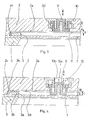
- a sheet-film cassette 1 comprises a lower portion 2 and an upper portion 3 which are connected with each other by a known type of hinge 4 not illustrated in detail.
- cassette 1 The upper and the lower portions of cassette 1 are locked by an automatically or manually actuated locking device 5 not illustrated in detail.
- the upper portion 3 of cassette 1 comprises an exposure window 3a which can be closed by a light-shielding slider 7 comprising a grip piece 6.
- the lower portion 2 of cassette 1 (shown in Figs. 3 and 4 in the top position to facilitate understanding of the invention) comprises a support surface 2a for a sheet film 11, which is surrounded by an uninterrupted frame 2c.
- the two shorter marginal areas 2b of support surface 2a are bent off upwardly by an angle of about 6° (see Fig. 4).
- Correspondingly shaped surface areas 3b on the upper portion 3 of cassette 1 are located opposite, and parallel to the marginal areas 2b.
- the longer sides of exposure window 3a have surface areas 3d extending parallel to the support surface 2a.
- a space "B" is provided which is adapted to receive a sheet film 11.
- the two shorter marginal areas of sheet film 11 are bent upwardly so that the sheet film is pretensioned in the direction of the support surface 2a of the lower portion 2 of cassette 1 and rests in a plane position on the support surface 2a.
- Lower portion 2 and upper portion 3 of cassette 1 are light-tight by the provision of labyrinth-type configurations not illustrated and further sealing means of a known type which are arranged in the area of the guide slot of light-shielding slider 7.
- cassette 1 is provided with a load-condition indicator device.
- the load-condition indicator device comprises a cylindrical indicator member 9 movable vertically to the support surface 2a of the sheet film.
- the indicator member 9 is guided in a sleeve 10 mounted in an opening 2d of the lower cassette portion 2, and under the action of its own weight, slides in an outwardly open bore 10a of sleeve 10.
- the inner wall of bore 10a is provided with a color mark 10b which, depending on the position of the indicator member 9, is either visible on the outer side of the cassette or covered.
- the indicator member 9 and the sleeve 10 are interlocked in a labyrinth-type manner to provide a light seal and are designed such that the indicator member 9 is movable to and fro over a distance "C".
- the indicator member 9 is arranged opposite to the opening of the exposure window 3a and is guided for movement over the distance "C" from a position in which it is flush with the outer surface of the lower cassette portion 2 to a position in which it enters to a limited extent the opening of the exposure window 3a.
- the cassette 1 is loaded in the position in which the lower cassette portion 2 is located at the bottom as shown in Fig. 2. In this position, the indicator member 9 is flush with the outer surface of the lower cassette portion 2 and does not extend beyond the support surface 2a for the sheet film 11.
- the cassette 1 In order to detect whether a sheet film 11 is present or not in a closed cassette 1, the cassette 1 is turned around such that the lower cassette portion 2 is at the top as shown in Fig. 3. With a sheet film 11 loaded, the indicator member 9 according to Fig. 3 contacts sheet film 11 and thus cannot move. This "cassette-loaded" condition can be recognized by the flush alignment of the indicator member 9 with the outer cassette surface and by the fact that the color mark 10b is covered.
- the indicator member 9 drops by its own weight by the distance "C" downwardly into the opening of the exposure window 3a as shown in Fig. 4.
- the load-condition indicator device 9, 10 is preferably arranged in the area adjacent to the locking device 8 for the light-shielding slider 7.
- the load-condition indicator device 9, 10 may also be arranged at another point opposite to the opening of the exposure window 3a.
- the plane position of sheet film 11 is affected by none of the arrangements possible because the indicator member 9 acts on the sheet film without spring-force, solely by the action of its own weight.
Landscapes
- Physics & Mathematics (AREA)
- General Physics & Mathematics (AREA)
- Displays For Variable Information Using Movable Means (AREA)
- Photographic Developing Apparatuses (AREA)
- Sheets, Magazines, And Separation Thereof (AREA)
- Details Of Cameras Including Film Mechanisms (AREA)
- Indication In Cameras, And Counting Of Exposures (AREA)
- Controlling Sheets Or Webs (AREA)
- Packaging Of Annular Or Rod-Shaped Articles, Wearing Apparel, Cassettes, Or The Like (AREA)
- Transition And Organic Metals Composition Catalysts For Addition Polymerization (AREA)
- Liquid Crystal (AREA)
Abstract
Description
- The invention relates to a sheet-film cassette with two cassette portions connected by a hinge, one portion of which comprises an exposure window which can be closed by a light-shielding slider and in the other portion of which a sheet film can be positioned, and with an indicator member movable relative to the outer surface of the cassette, said indicator member assuming a first detectable position when the cassette is loaded and a second detectable position when the cassette is not loaded.
- A cassette of the above type is known from DE-C 30 40 819 in which the use of a film-indicator device according to DE-C 28 38 058 is proposed. In accordance with DE-C 30 40 819 the film-indicator device is arranged in the upper portion of the cassette, which comprises the exposure window. However, owing to the limited space available the upper portion which forms a frame abound the exposure window is unsuitable for the arrangement of such a film-indicator device because the light-shielding slider is guided, the sheet film pressed onto its support, and the light-protecting labyrinth located, in this area.
- It is the object of the invention to design a sheet-film cassette of the generic type such that its film-indicator device does not necessitate any constructional restrictions.
- In accordance with the invention this object is attained in that the movable indicator member is arranged on the cassette portion which positions the sheet film and opposite to the opening of the exposure window.
- Advantageously, the indicator member according to the invention is cylindrical and is guided positively, and movable by its own weight in a bore arranged vertically to the plane of the sheet film.
- According to another useful modification of the invention the indicator member is movable from a position in which it is flush with the outer surface of the cassette portion positioning the sheet film to a position in which said bore is partially cleared, a color mark arranged in the bore becoming visible in said cleared position.
- Preferably the indicator member according to the invention is arranged at a suitable point of the cassette opposite to the opening of the exposure window and can enter unobstructedly the exposure window anyway available without any special constructional measures having to be taken.
- Further features and advantages can be inferred from the description of an embodiment of the invention illustrated in the drawings and from the subclaims. In the drawings
- Fig. 1
- shows a plan view of a sheet-film cassette;
- Fig. 2
- shows a lateral view of the cassette according to Fig. 1;
- Fig. 3
- shows a sectional view along line A-A with a sheet film loaded; and
- Fig. 4
- the device according to Fig. 3 with no sheet film present.
- A sheet-
film cassette 1 comprises alower portion 2 and anupper portion 3 which are connected with each other by a known type ofhinge 4 not illustrated in detail. - The upper and the lower portions of
cassette 1 are locked by an automatically or manually actuatedlocking device 5 not illustrated in detail. - The
upper portion 3 ofcassette 1 comprises anexposure window 3a which can be closed by a light-shielding slider 7 comprising agrip piece 6. A manuallyoperable locking device 8 for the light-shielding slider 7, which is not illustrated in detail, is arranged ongrip piece 6. - The
lower portion 2 of cassette 1 (shown in Figs. 3 and 4 in the top position to facilitate understanding of the invention) comprises asupport surface 2a for asheet film 11, which is surrounded by anuninterrupted frame 2c. The two shortermarginal areas 2b ofsupport surface 2a are bent off upwardly by an angle of about 6° (see Fig. 4). - Correspondingly shaped
surface areas 3b on theupper portion 3 ofcassette 1 are located opposite, and parallel to themarginal areas 2b. The longer sides ofexposure window 3a havesurface areas 3d extending parallel to thesupport surface 2a. - Between the
support surface 2a with its two bent-offmarginal areas 2b inlower portion 2 and theuninterrupted surface areas upper portion 3 which run parallel to saidsupport surface 2a, a space "B" is provided which is adapted to receive asheet film 11. - Due to the bent-off
marginal areas cassette 1 the two shorter marginal areas ofsheet film 11 are bent upwardly so that the sheet film is pretensioned in the direction of thesupport surface 2a of thelower portion 2 ofcassette 1 and rests in a plane position on thesupport surface 2a. -
Lower portion 2 andupper portion 3 ofcassette 1 are light-tight by the provision of labyrinth-type configurations not illustrated and further sealing means of a known type which are arranged in the area of the guide slot of light-shielding slider 7. - In order that it can be determined in the closed position of sheet-
film cassette 1 whether or not asheet film 11 has been loaded,cassette 1 is provided with a load-condition indicator device. - The load-condition indicator device comprises a
cylindrical indicator member 9 movable vertically to thesupport surface 2a of the sheet film. Theindicator member 9 is guided in asleeve 10 mounted in an opening 2d of thelower cassette portion 2, and under the action of its own weight, slides in an outwardlyopen bore 10a ofsleeve 10. The inner wall ofbore 10a is provided with acolor mark 10b which, depending on the position of theindicator member 9, is either visible on the outer side of the cassette or covered. - The
indicator member 9 and thesleeve 10 are interlocked in a labyrinth-type manner to provide a light seal and are designed such that theindicator member 9 is movable to and fro over a distance "C". - The
indicator member 9 is arranged opposite to the opening of theexposure window 3a and is guided for movement over the distance "C" from a position in which it is flush with the outer surface of thelower cassette portion 2 to a position in which it enters to a limited extent the opening of theexposure window 3a. - The
cassette 1 is loaded in the position in which thelower cassette portion 2 is located at the bottom as shown in Fig. 2. In this position, theindicator member 9 is flush with the outer surface of thelower cassette portion 2 and does not extend beyond thesupport surface 2a for thesheet film 11. - In order to detect whether a
sheet film 11 is present or not in a closedcassette 1, thecassette 1 is turned around such that thelower cassette portion 2 is at the top as shown in Fig. 3. With asheet film 11 loaded, theindicator member 9 according to Fig. 3contacts sheet film 11 and thus cannot move. This "cassette-loaded" condition can be recognized by the flush alignment of theindicator member 9 with the outer cassette surface and by the fact that thecolor mark 10b is covered. - However if there is no
sheet film 11 loaded incassette 1, theindicator member 9 drops by its own weight by the distance "C" downwardly into the opening of theexposure window 3a as shown in Fig. 4. - This clears the
color mark 10b in thebore 10a so that it is visible from outside that there is no sheet film loaded incassette 1. - When the
indicator member 9 drops inwardly by the distance "C" a recess is formed on the outer cassette surface by thebore 10a. This recess can be sensed so that the load condition can be ascertained even in a darkroom, without the cassette having to be opened. - As can be seen in particular from Fig. 1 the load-
condition indicator device locking device 8 for the light-shielding slider 7. - Since the operating means of the
locking device 8 of the light-shielding slider are associated with the same outer cassette surface as the load-condition indicator device 9, 10 (see Figs. 1 and 2), handling ofcassette 1 is facilitated because both means are located in the same field of vision. - In contrast with the embodiment just described the load-
condition indicator device exposure window 3a. - The plane position of
sheet film 11 is affected by none of the arrangements possible because theindicator member 9 acts on the sheet film without spring-force, solely by the action of its own weight.
Claims (5)
- Sheet-film cassette (1) with two cassette portions (2,3) connected by a hinge (4), one portion (3) of which comprises an exposure window (3a) which can be closed by a light-shielding slider (7) and in the other portion (2) of which a sheet film (11) can be positioned, and with an indicator member (9) movable relative to the outer surface of the cassetter (1), said indicator member (9) assuming a first detectable position when the cassette (1) is loaded and a second detectable position when the cassette (1) is not loaded, characterized in that the movable indicator member (9) is arranged on the cassette portion (2) which positions the sheet film (11) and opposite to the opening of the exposure window (3a).
- Sheet-film cassette according to claim 1, characterized in that the indicator member (9) is cylindrical and is positively guided and movable by its own weight in a bore (10a) arranged vertically to the plane of the sheet film.
- Sheet-film cassette according to claims 1 and 2, characterized in that the indicator member (9) is movable from a position in which it is flush with the outer surface of the cassette portion (2) positioning the sheet film to a position in which bore (10a) is partially cleared.
- Sheet-film cassette according to one or several of claims 1 to 3, characterized in that bore (10a) is provided with a color mark (10b).
- Sheet-film cassette according to one or several of claims 1 to 4, characterized in that the indicator member (9) and its guide means (10) are interlocked in a labyrinth-type manner.
Priority Applications (1)
| Application Number | Priority Date | Filing Date | Title |
|---|---|---|---|
| AT88903784T ATE82403T1 (en) | 1987-04-09 | 1988-04-08 | SHEET FILM CASSETTE. |
Applications Claiming Priority (2)
| Application Number | Priority Date | Filing Date | Title |
|---|---|---|---|
| DE3711997 | 1987-04-09 | ||
| DE19873711997 DE3711997A1 (en) | 1987-04-09 | 1987-04-09 | PLAN FILM CASSETTE |
Publications (2)
| Publication Number | Publication Date |
|---|---|
| EP0366657A1 EP0366657A1 (en) | 1990-05-09 |
| EP0366657B1 true EP0366657B1 (en) | 1992-11-11 |
Family
ID=6325227
Family Applications (1)
| Application Number | Title | Priority Date | Filing Date |
|---|---|---|---|
| EP88903784A Expired - Lifetime EP0366657B1 (en) | 1987-04-09 | 1988-04-08 | Sheet-film cassette |
Country Status (6)
| Country | Link |
|---|---|
| US (1) | US4969001A (en) |
| EP (1) | EP0366657B1 (en) |
| JP (1) | JPH063521B2 (en) |
| AT (1) | ATE82403T1 (en) |
| DE (2) | DE3711997A1 (en) |
| WO (1) | WO1988008152A1 (en) |
Citations (1)
| Publication number | Priority date | Publication date | Assignee | Title |
|---|---|---|---|---|
| DE3040819C2 (en) * | 1980-10-30 | 1983-10-20 | Agfa-Gevaert Ag, 5090 Leverkusen | Sheet film cassette |
Family Cites Families (4)
| Publication number | Priority date | Publication date | Assignee | Title |
|---|---|---|---|---|
| DE825947C (en) * | 1948-10-02 | 1951-12-27 | Optische Werke C A Steinheil S | Photographic cassette for plates, in particular for spectrographic purposes |
| US4248172A (en) * | 1978-08-31 | 1981-02-03 | _AGFA-Gevaert, A.G. | Film cassette |
| DE2838058C2 (en) * | 1978-08-31 | 1984-09-20 | Agfa-Gevaert Ag, 5090 Leverkusen | X=ray film cassette - indicates presence of film by spring pin resting with bottom against film but otherwise falling into hole |
| DE7928371U1 (en) * | 1979-10-05 | 1980-01-03 | Satzinger, Eduard, 8061 Guending | X-RAY FILM CASSETTE |
-
1987
- 1987-04-09 DE DE19873711997 patent/DE3711997A1/en not_active Withdrawn
-
1988
- 1988-04-08 EP EP88903784A patent/EP0366657B1/en not_active Expired - Lifetime
- 1988-04-08 AT AT88903784T patent/ATE82403T1/en not_active IP Right Cessation
- 1988-04-08 WO PCT/EP1988/000294 patent/WO1988008152A1/en not_active Ceased
- 1988-04-08 DE DE8888903784T patent/DE3875972T2/en not_active Expired - Fee Related
- 1988-04-08 JP JP63503487A patent/JPH063521B2/en not_active Expired - Fee Related
-
1989
- 1989-07-07 US US07/377,354 patent/US4969001A/en not_active Expired - Lifetime
Patent Citations (1)
| Publication number | Priority date | Publication date | Assignee | Title |
|---|---|---|---|---|
| DE3040819C2 (en) * | 1980-10-30 | 1983-10-20 | Agfa-Gevaert Ag, 5090 Leverkusen | Sheet film cassette |
Also Published As
| Publication number | Publication date |
|---|---|
| DE3875972T2 (en) | 1993-05-06 |
| EP0366657A1 (en) | 1990-05-09 |
| WO1988008152A1 (en) | 1988-10-20 |
| DE3875972D1 (en) | 1992-12-17 |
| US4969001A (en) | 1990-11-06 |
| DE3711997A1 (en) | 1988-10-27 |
| ATE82403T1 (en) | 1992-11-15 |
| JPH063521B2 (en) | 1994-01-12 |
| JPH02503041A (en) | 1990-09-20 |
Similar Documents
| Publication | Publication Date | Title |
|---|---|---|
| US5433314A (en) | Separable receptacle for receiving contact lenses | |
| US4725865A (en) | Disposable film package and holder for use therewith | |
| US4248172A (en) | Film cassette | |
| US4969001A (en) | Sheet-film cassette load indicator | |
| EP0396194A2 (en) | Universal evaporation cover | |
| US4653888A (en) | Indicator for indicating the presence or absence of a photo sensitive material in a film holder | |
| EP0371019B1 (en) | Sheet-film cassette | |
| US4410254A (en) | Pin registration back for film strip camera | |
| US5146484A (en) | Sheet-film cassette | |
| JP2524400Y2 (en) | Mounting structure of piston position detector | |
| JPS6319906Y2 (en) | ||
| CN221465327U (en) | Carrier tape detection device | |
| JPS6223302Y2 (en) | ||
| JPS6029111Y2 (en) | Cassette part confirmation device in cassette tape recorder | |
| JPS6224275Y2 (en) | ||
| JPH0619063Y2 (en) | Infrared sensing device | |
| US4247199A (en) | Frame for partial illumination in photocopying of negatives, diapositives and the like | |
| US5652780A (en) | Film presence indicator | |
| JPS5815858Y2 (en) | display device | |
| US5907732A (en) | Pressure plate spring | |
| US5105224A (en) | Document-plate-position determining device | |
| JPH0659836U (en) | Camera film detector | |
| JPS6128354Y2 (en) | ||
| JPS6331259Y2 (en) | ||
| KR0126148Y1 (en) | Slide locking structure for over head projector |
Legal Events
| Date | Code | Title | Description |
|---|---|---|---|
| PUAI | Public reference made under article 153(3) epc to a published international application that has entered the european phase |
Free format text: ORIGINAL CODE: 0009012 |
|
| 17P | Request for examination filed |
Effective date: 19891006 |
|
| AK | Designated contracting states |
Kind code of ref document: A1 Designated state(s): AT CH DE FR GB LI |
|
| 17Q | First examination report despatched |
Effective date: 19920415 |
|
| GRAA | (expected) grant |
Free format text: ORIGINAL CODE: 0009210 |
|
| AK | Designated contracting states |
Kind code of ref document: B1 Designated state(s): AT CH DE FR GB LI |
|
| REF | Corresponds to: |
Ref document number: 82403 Country of ref document: AT Date of ref document: 19921115 Kind code of ref document: T |
|
| REF | Corresponds to: |
Ref document number: 3875972 Country of ref document: DE Date of ref document: 19921217 |
|
| ET | Fr: translation filed | ||
| PLBE | No opposition filed within time limit |
Free format text: ORIGINAL CODE: 0009261 |
|
| STAA | Information on the status of an ep patent application or granted ep patent |
Free format text: STATUS: NO OPPOSITION FILED WITHIN TIME LIMIT |
|
| 26N | No opposition filed | ||
| REG | Reference to a national code |
Ref country code: GB Ref legal event code: IF02 |
|
| PGFP | Annual fee paid to national office [announced via postgrant information from national office to epo] |
Ref country code: AT Payment date: 20020313 Year of fee payment: 15 |
|
| PGFP | Annual fee paid to national office [announced via postgrant information from national office to epo] |
Ref country code: CH Payment date: 20020618 Year of fee payment: 15 |
|
| PGFP | Annual fee paid to national office [announced via postgrant information from national office to epo] |
Ref country code: GB Payment date: 20030313 Year of fee payment: 16 |
|
| PGFP | Annual fee paid to national office [announced via postgrant information from national office to epo] |
Ref country code: FR Payment date: 20030403 Year of fee payment: 16 |
|
| PG25 | Lapsed in a contracting state [announced via postgrant information from national office to epo] |
Ref country code: AT Free format text: LAPSE BECAUSE OF NON-PAYMENT OF DUE FEES Effective date: 20030408 |
|
| PG25 | Lapsed in a contracting state [announced via postgrant information from national office to epo] |
Ref country code: LI Free format text: LAPSE BECAUSE OF NON-PAYMENT OF DUE FEES Effective date: 20030430 Ref country code: CH Free format text: LAPSE BECAUSE OF NON-PAYMENT OF DUE FEES Effective date: 20030430 |
|
| PGFP | Annual fee paid to national office [announced via postgrant information from national office to epo] |
Ref country code: DE Payment date: 20030430 Year of fee payment: 16 |
|
| REG | Reference to a national code |
Ref country code: CH Ref legal event code: PL |
|
| PG25 | Lapsed in a contracting state [announced via postgrant information from national office to epo] |
Ref country code: GB Free format text: LAPSE BECAUSE OF NON-PAYMENT OF DUE FEES Effective date: 20040408 |
|
| PG25 | Lapsed in a contracting state [announced via postgrant information from national office to epo] |
Ref country code: DE Free format text: LAPSE BECAUSE OF NON-PAYMENT OF DUE FEES Effective date: 20041103 |
|
| GBPC | Gb: european patent ceased through non-payment of renewal fee |
Effective date: 20040408 |
|
| PG25 | Lapsed in a contracting state [announced via postgrant information from national office to epo] |
Ref country code: FR Free format text: LAPSE BECAUSE OF NON-PAYMENT OF DUE FEES Effective date: 20041231 |
|
| REG | Reference to a national code |
Ref country code: FR Ref legal event code: ST |