EP0366562A1 - Detachable holding device for a piezoelectric resonator inside a housing - Google Patents
Detachable holding device for a piezoelectric resonator inside a housing Download PDFInfo
- Publication number
- EP0366562A1 EP0366562A1 EP89402975A EP89402975A EP0366562A1 EP 0366562 A1 EP0366562 A1 EP 0366562A1 EP 89402975 A EP89402975 A EP 89402975A EP 89402975 A EP89402975 A EP 89402975A EP 0366562 A1 EP0366562 A1 EP 0366562A1
- Authority
- EP
- European Patent Office
- Prior art keywords
- resonator
- springs
- housing
- clamps
- clamp
- Prior art date
- Legal status (The legal status is an assumption and is not a legal conclusion. Google has not performed a legal analysis and makes no representation as to the accuracy of the status listed.)
- Granted
Links
- 229910045601 alloy Inorganic materials 0.000 claims abstract description 5
- 239000000956 alloy Substances 0.000 claims abstract description 5
- 239000002184 metal Substances 0.000 claims abstract description 5
- 239000000463 material Substances 0.000 claims description 11
- 229910001092 metal group alloy Inorganic materials 0.000 claims 1
- 230000001747 exhibiting effect Effects 0.000 abstract 1
- 239000013078 crystal Substances 0.000 description 16
- 239000000725 suspension Substances 0.000 description 9
- 230000001464 adherent effect Effects 0.000 description 8
- 238000004519 manufacturing process Methods 0.000 description 6
- 239000010453 quartz Substances 0.000 description 6
- VYPSYNLAJGMNEJ-UHFFFAOYSA-N silicon dioxide Inorganic materials O=[Si]=O VYPSYNLAJGMNEJ-UHFFFAOYSA-N 0.000 description 6
- 238000005452 bending Methods 0.000 description 4
- 230000002093 peripheral effect Effects 0.000 description 4
- 230000035939 shock Effects 0.000 description 4
- 230000001681 protective effect Effects 0.000 description 3
- 230000035882 stress Effects 0.000 description 3
- 230000001133 acceleration Effects 0.000 description 2
- 238000003466 welding Methods 0.000 description 2
- 229910000831 Steel Inorganic materials 0.000 description 1
- 230000032683 aging Effects 0.000 description 1
- 230000006835 compression Effects 0.000 description 1
- 238000007906 compression Methods 0.000 description 1
- 230000007547 defect Effects 0.000 description 1
- 230000000694 effects Effects 0.000 description 1
- 230000005284 excitation Effects 0.000 description 1
- 230000005484 gravity Effects 0.000 description 1
- 230000003100 immobilizing effect Effects 0.000 description 1
- 239000011810 insulating material Substances 0.000 description 1
- 239000010959 steel Substances 0.000 description 1
Images

Classifications
-
- H—ELECTRICITY
- H03—ELECTRONIC CIRCUITRY
- H03H—IMPEDANCE NETWORKS, e.g. RESONANT CIRCUITS; RESONATORS
- H03H9/00—Networks comprising electromechanical or electro-acoustic devices; Electromechanical resonators
- H03H9/02—Details
- H03H9/05—Holders; Supports
- H03H9/0504—Holders; Supports for bulk acoustic wave devices
- H03H9/0528—Holders; Supports for bulk acoustic wave devices consisting of clips
-
- H—ELECTRICITY
- H03—ELECTRONIC CIRCUITRY
- H03H—IMPEDANCE NETWORKS, e.g. RESONANT CIRCUITS; RESONATORS
- H03H9/00—Networks comprising electromechanical or electro-acoustic devices; Electromechanical resonators
- H03H9/02—Details
- H03H9/05—Holders; Supports
- H03H9/09—Elastic or damping supports
Definitions
- the present invention which is due to the work of Messrs R. Besson, R. Delaite, G. Renard, JP Valentin and JL Vaterkowski of the Chronometry, Electronics and Piezoelectricity Laboratory of the National School of Mechanics and Microtechnics of University of Franche-Comté - Besancon, concerns the mechanical structures for supporting piezoelectric resonators and more particularly a removable device for supporting a piezoelectric resonator inside a housing, comprising four identical independent U-shaped clamps which are produced in a material whose coefficient of expansion in the axial direction of the resonator is practically identical to that of the material constituting the resonator and which each cooperate with a pair of springs each consisting of a round metal wire made of an alloy with high elastic limit, the whole clamps and springs having symmetry with respect to two planes s axial of the resonator perpendicular to each other, as well as with respect to a median radial plane of the resonator.
- a resonator crystal is constituted by a plano-convex or bi-convex quartz plate with circular outline, on the front faces of which are directly deposited metal electrodes, called adherent electrodes.
- the quartz plate with adherent electrodes is externally limited by a quartz crown serving to support the crystal-resonator.
- the crystal-resonator is connected to a quartz crown by bridges cut in the mass.
- the electrodes can be adherent or non-adherent. In the latter case, the electrodes are deposited on quartz plates of the same cut as the crystal and of similar shape and only the crowns of the electro-support plates. are in contact with the crown of the vibrating crystal.
- resonator Whatever type of resonator is used, it is generally necessary to incorporate this resonator in a protective case which, if it is waterproof, also makes it possible to create a space in which there is a more or less high vacuum which improves the operating conditions of the resonator and therefore the quality of the latter.
- the housing and the crystal-resonator however have different mechanical and thermal characteristics, so it is necessary to produce a specific mechanical structure making it possible to limit the influence of external disturbances by bringing the minimum of stresses to the center of the crystal.
- first and second identical half-shells for positioning the resonator which are made of a material of the same nature and of the same section as that making up the resonator, each have the shape of a cross-piece and each have four branches the free ends of which define angles having a horizontal surface of small surface area slightly raised with respect to the central part of the corresponding half-shell and a vertical branch for retaining the edge of the resonator; and four identical independent clamps for immobilizing the two half-shells which have the shape of a lying U and each have at the ends of each branch of the U two stop elements bearing on two superposed branches of the two half-shells, on the faces of the branches opposite to said horizontal spans cooperate with four pairs of suspension springs connecting the four flanges immobilization to the housing.
- the suspension springs of the retaining flanges of the cross-shaped half-shells are connected directly to the housing and immobilized by one of their ends at the junction between different walls constituting the housing. This prevents obtaining a complete decoupling between the housing, the main role of which is to maintain the vacuum in the space internal to the housing, and which can be subjected to shocks or deformations, and the actual suspension which must remain the most symmetrical possible. Furthermore, the production of half-shells in the shape of a cross in a material of the same nature and of the same cut as that making up the resonator constitutes a constraint in terms of manufacturing cost.
- the present invention aims precisely to remedy the aforementioned drawbacks and to allow the production of a resonator support device in a housing which is simpler and less costly to manufacture than existing devices, and which moreover ensures more effective decoupling between the housing and the suspension members of the resonator, while also allowing easy disassembly and reassembly of the suspension members.
- a support device of the type defined at the head of the description characterized in that it further comprises a removable cylindrical part placed inside the housing in the vicinity of the side wall of the housing, extending over the entire height of the internal space defined between the upper and lower walls of the housing and having on its internal face a circular groove situated in a median plane parallel to the upper and lower walls of the housing, in that for each pair of springs cooperating with the same clamp, one of the springs is engaged by a first portion in an upper groove formed in the flat rear face of said clamp at the upper part thereof, and by a second portion in said circular groove while the other spring is engaged by a first portion in a lower groove formed in the flat rear face of said clamp at the lower part thereof, and by a second portion in said circular groove, and said second portions of the springs engaged in said circular groove are secured to each other and project backwards relative to the rear face of said clamp, and in that the internal faces of the clamps substantially perpendicular to the rear face of said clamps rest directly on the pe
- the circular groove has an annular shape with rectangular section.
- the cylindrical part is metallic and has a shoulder at one of its ends to provide a free space between the side wall of the housing and the cylindrical part over most of the height thereof.
- the internal faces of the clamps substantially perpendicular to the rear face have a regular surface in contact with the upper and lower external faces of the resonator or of the support discs of the electrodes of the resonator over an area extending radially over a distance on the order of 1 to 2 mm.
- recesses are formed in the walls of the support discs for the electrodes of the resonator in areas extending radially towards the center of the resonator the areas at which the clamps are in contact with the upper external faces and support discs over a distance of about 1 to 2 mm.
- the springs have an interruption at their first portion engaged in a groove on the rear face of the clamp with which they cooperate, are symmetrical with respect to a vertical radial plane situated at the level of said interruption and have a configuration such that each half-spring divided by said vertical radial plane of symmetry comprises a first part horizontal rectilinear intended to be embedded in a groove of the receiving clamp, a curved vertical part disposed outside of the receiving clamp in a plane forming an angle of 45 ° relative to the plane of symmetry of the spring, and a second horizontal part which is connected to the end of the curved vertical part remote from the first horizontal part and constitutes a part of said second portion situated behind the first rectilinear horizontal part which itself constitutes a part of said first portion .
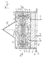
- FIGS. 1 and 2 show all of the removable means for supporting a resonator 1 inside a protective box 10.
- FIG. 1 a housing arranged according to FIG. 1 and the terms "lower, upper, vertical, horizontal," used in the present description, are to be interpreted in conjunction with the description of this figure 1 and aim to allow a description of the various elements in their relative positions from the position of Figure 1.
- the housing 10 can naturally be placed in all kinds of other positions and said terms "lower, upper, vertical, horizontal” should therefore not be considered as limiting with regard to the position of the housing 10.
- the resonator 1 may be constituted by a crystal-resonator with adherent electrodes, that is to say by a plate of a piezoelectric material of cut given on the main faces of which are arranged metal electrodes.
- the resonator 1 may however also be constituted by a more complex assembly, such as that shown in elevation in FIG. 1, with a resonator crystal 101 constituted, as in the previous case, by a plate of a piezoelectric material for example of the type bi-plane, but without electrodes and having an external support ring 110 delimited by lights 111 and connected to the active central part of the crystal by bridges and two plates 102, 103 also each having a peripheral support part which carries on the outer ring 110 of the crystal itself, so as to form at this ring a stack of surfaces adjusted to one another.
- a resonator crystal 101 constituted, as in the previous case, by a plate of a piezoelectric material for example of the type bi-plane, but without electrodes and having an external support ring 110 delimited by lights 111 and connected to the active central part of the crystal by bridges and two plates 102, 103 also each having a peripheral support part which carries on the outer ring 110 of the crystal itself, so as to form
- the central parts 121, 131 of the faces of the plates 102, 103, located opposite the crystal 101, and which are not in contact with the latter carry so-called excitation electrodes non-adherent electrodes 122, 132.
- the compact assembly constituted by the crystal 101 and the plates 102, 103 carrying electrodes can then be considered as a block equivalent to a resonator with adherent electrodes, the elements of the resonator support device acting in this case on the peripheral parts of the electrode support plates while in the case of a resonator with adherent electrodes, the support device is in contact with the peripheral part of the crystal-resonator itself.
- references 123 and 133 designate conductive paths connecting the electrodes 122, 132 to pads 124, 134 respectively intended to allow electrical connections to be made with the connection pins 17, 18, 19 by wires not shown in the drawings.
- the whole of the support device according to the invention is designed so as to be entirely symmetrical with respect to two axial planes of the resonator 1 perpendicular to each other, as well as with respect to a median radial plane of the resonator 1 and to achieve complete decoupling between the protective housing and the resonator so that actions due to external disturbances (accelerations, shocks, vibrations, pressure) cannot transmit torsion or bending moments to the center of the crystal.
- the support means are further designed to include a limited number of parts and to be removable.
- a first element constituting the means for supporting the resonator 1 in the housing is constituted by a removable cylindrical part 6, made of steel, which is disposed between the flat wall 12 of the base of the housing, which constitutes the bottom of the cavity formed inside the housing, and the upper wall 13 of the housing cover.
- the cylindrical part 6 is placed in the vicinity of the cylindrical side wall 11 of the housing cover and has on its internal face a circular groove 62 situated in a median plane parallel to the upper 13 and lower 12 walls of the housing 10.
- the groove 62 has a annular shape with rectangular section and is intended to receive by snap-fastening of the adjoining parts of a pair of springs 5 which will be described later.
- the cylindrical part 6 has a shoulder 61 at one of its ends to provide a free space 60 between the side wall 11 of the housing 10 and the cylindrical part 6 over most of the height thereof.
- the means for supporting the whole of the resonator 1 which, as shown in the figures, may consist of a stack of three discs, namely two discs 102, 103 supporting electrodes and a central disc 101 constituting the resonator proper , include four identical independent clamps 4 arranged at 90 ° from each other, and cooperating directly with the upper external 126 and lower 136 faces of the resonator.
- Each clamp 4 has the shape of a coated U and comprises a flat vertical part 41 in the rear face of which two horizontal grooves 46, 47 are formed in the vicinity of the lateral branches 42, 43 of the clamp 4.
- the clamping forces applied by the four clamps 4 are identical, collinear and exerted perpendicular to the upper outer 126 and lower 136 faces of the resonator 1 so that no bending moment is transmitted to it.
- a material is chosen for the clamps whose coefficient of expansion is in the axial direction, identical to, or very close to that of crystal 1.
- a quartz crystal one can thus choose a material of the type of that known under the name PHYNOX.
- the "suspension" function of the crystal assembly 1 with its disks 102, 103 electrode support and the clamps 4 in the housing 10 is provided by eight identical springs 5 which connect the clamps 4 to the cylindrical part 6.
- the combination of a cylindrical part 6 distinct from the housing 10 and springs 5 effectively isolates the sensitive part of the resonator 1 from the external actions applied to the housing 10.
- the springs 5 also make it possible to compensate for manufacturing defects between the various assembled elements.
- the suspension is designed symmetrically so that the actions due to external disturbances (accelerations, shocks, vibrations, pressure) are not likely to transmit moments of torsion or bending in the center of the crystal.
- Eight springs of shape 5 are thus arranged two by two at 90 ° from each other, each pair of springs acting on the lower and upper parts of a clamp 4.
- the arrangement of springs 5, their particular shape shown in Figures 1 to 3 and the use of round wire of small section, for example with a diameter of 2 tenths of a millimeter, for the production of the springs 5 make it possible to guarantee that the elastic center of the suspension corresponds with the center of gravity of the mass of the system, that the three degrees of freedom are in translation, and that with these are associated three identical stiffness coefficients.
- the assembly may be subjected to shocks; it is the suspension which is capable of "absorbing” them and minimizing their influences.
- the springs 5 being able to work in torsion and in bending, it is advisable to choose to carry out a special alloy with high elastic limit (for example an alloy of the type known under the name PHYNOX).
- the springs 5 which make the connection between the clamps and the cylindrical piece 6, can be simply embedded in the groove 62 of the cylindrical piece 6, so that the assembly consisting of the clamps 4 and the springs 5 can be disassembled relative to the cylindrical part 6, if necessary, and naturally with respect to the resonator 1.
- connection with the springs 5 can be made by welding, the relative positioning being ensured by the two grooves 46, 47 cut on the back of each clamp 4.
- one of the springs is engaged by a first portion 51, 52 in the upper groove 46 formed in the flat rear face 41 of the clamp 4 at the upper part thereof, and by a second portion 57 in the circular groove 62 of the cylindrical part 6 while the other spring is engaged by a first portion 51, 52 in the lower groove 47 formed in the flat rear face 41 of the clamp 4 at the lower part thereof and by a second portion 57 in the circular groove 62.
- the second portions 57 of the springs engaged in the circular groove 62 are joined together for example by laser welding and are projected in rear relative to the rear face 41 of the clamp over a distance of between approximately 1 and 2 mm and preferably of the order of 1.5 mm.
- the springs 5 have an interruption 50 at their first portion 51, 52 engaged in a groove 46 or 47 of the rear face of the clamp with which they cooperate.
- the springs 5 are symmetrical with respect to a plane situated at the level of said interruption 50, which corresponds to the vertical median plane of a clamp 4.
- Each half-spring divided by said vertical radial plane of symmetry comprises a first rectilinear horizontal part 51; 52 intended to be fitted into a groove 46 or 47 of the receiving clamp 4, a curved vertical part 53; 54 corresponding approximately to a fraction of a circle disposed outside of the receiving clamp 4 in a plane forming an angle of 45 ° relative to the plane of symmetry of the spring, and a second horizontal part 57 which is connected to the end 55 ; 56 of the curved vertical part 53; 54 remote from the first horizontal part 51; 52 and constitutes a part of said second portion 57 situated behind the first rectilinear horizontal part 51; 52 which itself constitutes a part of said first portion.
- the internal faces 42, 43 of the clamps 4 substantially perpendicular to the rear face 41 have a surface regular in contact with the upper and lower external faces 126, 136 of the disks 102, 103 for supporting the electrodes of the resonator over an area extending radially over a distance of the order of 1 to 2 mm.
- recesses 125, 135 are formed in the walls of the discs 102, 103 for supporting the electrodes of the resonator 1 in areas extending radially towards the center of the resonator the areas at which the clamps 4 are in contact with the upper and lower external faces 126, 136 of the support discs 102, 103 over a distance of the order of 1 to 2 mm, in order to prevent the clamps 4 which are directly engaged with the peripheral parts of the discs 102, 103 transmit stresses to the central parts of the discs 102, 103 and consequently of the crystal 101 constituting the resonator proper.
Landscapes
- Physics & Mathematics (AREA)
- Acoustics & Sound (AREA)
- Piezo-Electric Or Mechanical Vibrators, Or Delay Or Filter Circuits (AREA)
Abstract
Description
La présente invention, qui est due aux travaux de Messieurs R. Besson, R. Delaite, G. Renard, J.P. Valentin et J.L. Vaterkowski du Laboratoire de Chronométrie, Electronique et Piézoélectricité de l'Ecole Nationale Supérieure de Mécanique et des Microtechniques de l'Université de Franche-Comté - Besancon, concerne les structures mécaniques de support de résonateurs piézoélectriques et plus particulièrement un dispositif démontable de support de résonateur piézoélectrique à l'intérieur d'un boîtier, comprenant quatre pinces indépendantes identiques en forme de U qui sont réalisées en un matériau dont le coefficient de dilatation dans le sens axial du résonateur est pratiquement identique à celui du matériau constituant le résonateur et qui coopèrent chacune avec une paire de ressorts constitués chacun par un fil métallique rond en un alliage à haute limite élastique, l'ensemble des pinces et des ressorts présentant une symétrie par rapport à deux plans axiaux du résonateur perpendiculaires entre eux, ainsi que par rapport à un plan radial médian du résonateur.The present invention, which is due to the work of Messrs R. Besson, R. Delaite, G. Renard, JP Valentin and JL Vaterkowski of the Chronometry, Electronics and Piezoelectricity Laboratory of the National School of Mechanics and Microtechnics of University of Franche-Comté - Besancon, concerns the mechanical structures for supporting piezoelectric resonators and more particularly a removable device for supporting a piezoelectric resonator inside a housing, comprising four identical independent U-shaped clamps which are produced in a material whose coefficient of expansion in the axial direction of the resonator is practically identical to that of the material constituting the resonator and which each cooperate with a pair of springs each consisting of a round metal wire made of an alloy with high elastic limit, the whole clamps and springs having symmetry with respect to two planes s axial of the resonator perpendicular to each other, as well as with respect to a median radial plane of the resonator.
On connait divers exemples de résonateurs piézoélectriques.Various examples of piezoelectric resonators are known.
Selon un premier exemple classique, un cristal résonateur est constitué par une plaquette de quartz plan-convexe ou bi-convexe à contour circulaire, sur les faces frontales de laquelle sont déposées directement des électrodes métalliques, dites électrodes adhérentes.According to a first conventional example, a resonator crystal is constituted by a plano-convex or bi-convex quartz plate with circular outline, on the front faces of which are directly deposited metal electrodes, called adherent electrodes.
Selon un autre exemple de réalisation, la plaquette de quartz à électrodes adhérentes est limitée extérieurement par une couronne en quartz servant au support du cristal-résonateur.According to another embodiment, the quartz plate with adherent electrodes is externally limited by a quartz crown serving to support the crystal-resonator.
Selon encore un autre exemple de réalisation, le cristal-résonateur est relié à une couronne en quartz par des ponts taillés dans la masse. Les électrodes peuvent être adhérentes ou non adhérentes. Dans ce dernier cas, les électrodes sont déposées sur des plaquettes de quartz de même coupe que le cristal et de forme similaire et seules les couronnes des plaquettes-support d'électro des sont en contact avec la couronne du cristal vibrant.According to yet another exemplary embodiment, the crystal-resonator is connected to a quartz crown by bridges cut in the mass. The electrodes can be adherent or non-adherent. In the latter case, the electrodes are deposited on quartz plates of the same cut as the crystal and of similar shape and only the crowns of the electro-support plates. are in contact with the crown of the vibrating crystal.
Quel que soit le type de résonateur utilisé, il est en général nécessaire d'incorporer ce résonateur dans un boîtier de protection qui, s'il est étanche, permet en outre de créer un espace dans lequel règne un vide plus ou moins poussé qui améliore les conditions de fonctionnement du résonateur et partant la qualité de celui-ci.Whatever type of resonator is used, it is generally necessary to incorporate this resonator in a protective case which, if it is waterproof, also makes it possible to create a space in which there is a more or less high vacuum which improves the operating conditions of the resonator and therefore the quality of the latter.
Le boîtier et le cristal-résonateur présentent cependant des caractéristiques mécaniques et thermiques différentes, de sorte qu'il est nécessaire de réaliser une structure mécanique spécifique permettant de limiter l'influence des perturbations extérieures en rapportant le minimum de contraintes au centre du cristal.The housing and the crystal-resonator however have different mechanical and thermal characteristics, so it is necessary to produce a specific mechanical structure making it possible to limit the influence of external disturbances by bringing the minimum of stresses to the center of the crystal.
On a déjà proposé par le document US-A-4 705 982 de réaliser un dispositif de support d'un résonateur piézoélectrique à l'intérieur d'un boîtier applicable à différents types de résonateurs piézoélectriques, conçu pour minimiser les variations relatives de fréquence du résonateur sous l'influence de perturbations accélérométriques, thermiques ou de pression, afin de conférer au résonateur une stabilité maximale dans le temps et un vieillissement aussi faible que possible.It has already been proposed by document US-A-4 705 982 to produce a device for supporting a piezoelectric resonator inside a housing applicable to different types of piezoelectric resonators, designed to minimize the relative frequency variations of the resonator under the influence of accelerometric, thermal or pressure disturbances, in order to give the resonator maximum stability over time and as little aging as possible.
Selon ce dispositif de support connu, des première et deuxième demi-coques identiques de positionnement du résonateur qui sont en un matériau de même nature et de même coupe que celui composant le résonateur, présentent chacune la forme d'un croisillon et comportent chacune quatre branches dont les extrémités libres définissent des cornières présentant une portée horizontale de faible surface légèrement rehaussée par rapport à la partie centrale de la demi-coque correspondante et une branche verticale de retenue de la tranche du résonateur; et quatre brides indépendantes identiques d'immobilisation des deux demi-coques qui présentent la forme d'un U couché et comportent chacune aux extrémités de chaque branche du U deux éléments d'arrêt portant sur deux branches superposées des deux demi-coques, sur les faces des branches opposées auxdites portées horizontales coopèrent avec quatre paires de ressorts de suspension reliant les quatre brides d'immobilisation au boîtier.According to this known support device, first and second identical half-shells for positioning the resonator which are made of a material of the same nature and of the same section as that making up the resonator, each have the shape of a cross-piece and each have four branches the free ends of which define angles having a horizontal surface of small surface area slightly raised with respect to the central part of the corresponding half-shell and a vertical branch for retaining the edge of the resonator; and four identical independent clamps for immobilizing the two half-shells which have the shape of a lying U and each have at the ends of each branch of the U two stop elements bearing on two superposed branches of the two half-shells, on the faces of the branches opposite to said horizontal spans cooperate with four pairs of suspension springs connecting the four flanges immobilization to the housing.
Dans un tel dispositif connu de support d'un résonateur, les ressorts de suspension des brides de retenue des demi-coques en forme de croix sont reliés directement au boîtier et immobilisés par une de leurs extrémités à la jonction entre différentes parois constituant le boîtier. Ceci empêche d'obtenir un découplage complet entre le boîtier, dont le rôle principal est de maintenir le vide dans l'espace interne au boîtier, et qui peut être soumis à des chocs ou déformations, et la suspension proprement dite qui doit rester la plus symétrique possible. Par ailleurs, la réalisation de demi-coques en forme de croix dans un matériau de même nature et de même coupe que celui composant le résonateur, constitue une contrainte en matière de coût de fabrication.In such a known device for supporting a resonator, the suspension springs of the retaining flanges of the cross-shaped half-shells are connected directly to the housing and immobilized by one of their ends at the junction between different walls constituting the housing. This prevents obtaining a complete decoupling between the housing, the main role of which is to maintain the vacuum in the space internal to the housing, and which can be subjected to shocks or deformations, and the actual suspension which must remain the most symmetrical possible. Furthermore, the production of half-shells in the shape of a cross in a material of the same nature and of the same cut as that making up the resonator constitutes a constraint in terms of manufacturing cost.
La présente invention vise précisément à remédier aux inconvénients précités et à permettre la réalisation d'un dispositif de support de résonateur dans un boîtier qui soit plus simple et moins coûteux à fabriquer que les dispositifs existants, et qui de plus assure un découplage plus efficace entre le boîtier et les organes de suspension du résonateur, en autorisant par ailleurs un démontage et un remontage aisés des organes de suspension.The present invention aims precisely to remedy the aforementioned drawbacks and to allow the production of a resonator support device in a housing which is simpler and less costly to manufacture than existing devices, and which moreover ensures more effective decoupling between the housing and the suspension members of the resonator, while also allowing easy disassembly and reassembly of the suspension members.
Ces buts sont atteints grâce à un dispositif de support du type défini en tête de la description, caractérisé en ce qu'il comprend en outre une pièce cylindrique amovible placée à l'intérieur du boîtier au voisinage de la paroi latérale du boîtier, s'étendant sur toute la hauteur de l'espace interne défini entre les parois supérieure et inférieure du boîtier et présentant sur sa face interne une gorge circulaire située dans un plan médian parallèle aux parois supérieure et inférieure du boîtier, en ce que pour chaque paire de ressorts coopérant avec une même pince, l'un des ressorts est engagé par une première portion dans une rainure supérieure formée dans la face arrière plane de ladite pince à la partie supérieure de celle-ci, et par une seconde portion dans ladite gorge circulaire tandis que l'autre ressort est engagé par une première portion dans une rainure inférieure formée dans la face arrière plane de ladite pince à la partie inférieure de celle-ci, et par une seconde portion dans ladite gorge circulaire, et lesdites secondes portions des ressorts engagées dans ladite gorge circulaire sont solidarisées entre elles et se projettent en arrière par rapport à la face arrière de ladite pince, et en ce que les faces internes des pinces sensiblement perpendiculaires à la face arrière desdites pinces reposent directement sur la périphérie des faces externes supérieure et inférieure du résonateur ou des disques de support des électrodes du résonateur.These aims are achieved by means of a support device of the type defined at the head of the description, characterized in that it further comprises a removable cylindrical part placed inside the housing in the vicinity of the side wall of the housing, extending over the entire height of the internal space defined between the upper and lower walls of the housing and having on its internal face a circular groove situated in a median plane parallel to the upper and lower walls of the housing, in that for each pair of springs cooperating with the same clamp, one of the springs is engaged by a first portion in an upper groove formed in the flat rear face of said clamp at the upper part thereof, and by a second portion in said circular groove while the other spring is engaged by a first portion in a lower groove formed in the flat rear face of said clamp at the lower part thereof, and by a second portion in said circular groove, and said second portions of the springs engaged in said circular groove are secured to each other and project backwards relative to the rear face of said clamp, and in that the internal faces of the clamps substantially perpendicular to the rear face of said clamps rest directly on the periphery of the upper and lower external faces of the resonator or of the support discs for the electrodes of the resonator.
De préférence, la gorge circulaire présente une forme annulaire à section rectangulaire.Preferably, the circular groove has an annular shape with rectangular section.
La pièce cylindrique est métallique et présente un épaulement à l'une de ses extrémités pour ménager un espace libre entre la paroi latérale du boîtier et la pièce cylindrique sur la majeure partie de la hauteur de celle-ci.The cylindrical part is metallic and has a shoulder at one of its ends to provide a free space between the side wall of the housing and the cylindrical part over most of the height thereof.
Selon une caractéristique particulière, les faces internes des pinces sensiblement perpendiculaires à la face arrière présentent une surface régulière en contact avec les faces externes supérieure et inférieure du résonateur ou des disques de support des électrodes du résonateur sur une zone s'étendant radialement sur une distance de l'ordre de 1 à 2 mm.According to a particular characteristic, the internal faces of the clamps substantially perpendicular to the rear face have a regular surface in contact with the upper and lower external faces of the resonator or of the support discs of the electrodes of the resonator over an area extending radially over a distance on the order of 1 to 2 mm.
De préférence, afin de limiter les contraintes, des évidements sont formés dans les parois des disques de support des électrodes du résonateur dans des zones prolongeant radialement vers le centre du résonateur les zones au niveau desquelles les pinces sont en contact avec les faces externes supérieure et inférieure des disques de support sur une distance de l'ordre de 1 à 2 mm.Preferably, in order to limit the stresses, recesses are formed in the walls of the support discs for the electrodes of the resonator in areas extending radially towards the center of the resonator the areas at which the clamps are in contact with the upper external faces and support discs over a distance of about 1 to 2 mm.
De façon plus particulière, les ressorts présentent une interruption au niveau de leur première portion engagée dans une rainure de la face arrière de la pince avec laquelle ils coopèrent, sont symétriques par rapport à un plan radial vertical situé au niveau de ladite interruption et présentent une configuration telle que chaque demi-ressort divisé par ledit plan de symétrie radial vertical comprend une première partie horizontale rectiligne destinée à venir s'encastrer dans une rainure de la pince réceptrice, une partie verticale courbe disposée à l'extérieur de la pince réceptrice dans un plan formant un angle de 45° par rapport au plan de symétrie du ressort, et une seconde partie horizontale qui est reliée à l'extrémité de la partie verticale courbe éloignée de la première partie horizontale et constitue une partie de ladite seconde portion située en arrière par rapport à la première partie horizontale rectiligne qui constitue elle-même une partie de ladite première portion.More particularly, the springs have an interruption at their first portion engaged in a groove on the rear face of the clamp with which they cooperate, are symmetrical with respect to a vertical radial plane situated at the level of said interruption and have a configuration such that each half-spring divided by said vertical radial plane of symmetry comprises a first part horizontal rectilinear intended to be embedded in a groove of the receiving clamp, a curved vertical part disposed outside of the receiving clamp in a plane forming an angle of 45 ° relative to the plane of symmetry of the spring, and a second horizontal part which is connected to the end of the curved vertical part remote from the first horizontal part and constitutes a part of said second portion situated behind the first rectilinear horizontal part which itself constitutes a part of said first portion .
D'autres caractéristiques et avantages de l'invention ressortiront de la description suivante d'un mode particulier de réalisation, donné à titre d'exemple, en référence aux dessins annexés sur lesquels :
- - la figure 1 est une vue en coupe axiale selon un plan de symétrie d'un boîtier incorporant un dispositif de support démontable de résonateur à l'intérieur d'un boîtier, conformément à l'invention,
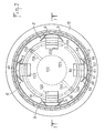
- - la figure 2 est une vue en coupe du dispositif de la figure 1 selon la ligne II-II de cette figure 1, et
- - la figure 3 est une vue en perspective montrant une partie des moyens de support selon l'invention avec une pince et une paire de ressorts qui coopèrent d'une part avec une pièce cylindrique intermédiaire distincte du boîtier et d'autre part, directement avec le résonateur.
- FIG. 1 is a view in axial section along a plane of symmetry of a box incorporating a removable resonator support device inside a box, in accordance with the invention,
- FIG. 2 is a sectional view of the device in FIG. 1 along the line II-II of this FIG. 1, and
- - Figure 3 is a perspective view showing part of the support means according to the invention with a clamp and a pair of springs which cooperate on the one hand with an intermediate cylindrical part separate from the housing and on the other hand, directly with the resonator.
Les figures 1 et 2 montrent l'ensemble des moyens démontables de support d'un résonateur 1 à l'intérieur d'un boîtier de protection 10.FIGS. 1 and 2 show all of the removable means for supporting a
Le boîtier 10 comporte de façon classique un capot présentant une paroi latérale cylindrique 11 et une partie supérieure 13 munie d'un prolongement 13a muni d'une fente qui permet de faire le vide à l'intérieur du boîtier avant d'être obturée de façon hermétique. Le capot repose par une aile annulaire 15 sur une aile annulaire 16 d'une embase 14, les deux ailes 15, 16 étant prévues pour être fixées de façon étanche l'une à l'autre. L'embase présente une paroi latérale cylindrique 14 de faible hauteur qui vient s'engager à l'intérieur du capot, et une paroi plane supérieure 12 qui est traversée par des broches de connexion isolées 17, 18, 19. Une matière isolante 14a, qui peut enrober des composants électroniques associés au résonateur 1 placé dans le boîtier, est coulée dans l'espace libre délimité par la paroi latérale cylindrique et la paroi plane supérieure 12 de l'embase.The housing 10 conventionally comprises a cover having a
Dans toute la présente description, on se référera à un boîtier disposé selon la figure 1 et les termes "inférieur, supérieur, vertical, horizontal," utilisés dans la présente description, sont à interpréter en liaison avec la description de cette figure 1 et visent à permettre une description des divers éléments dans leurs positions relatives à partir de la position de la figure 1. Le boîtier 10 peut naturellement être placé dans toutes sortes d'autres positions et lesdits termes "inférieur, supérieur, vertical, horizontal" ne doivent donc pas être considérés comme limitatifs en ce qui concerne la position du boîtier 10.Throughout the present description, reference will be made to a housing arranged according to FIG. 1 and the terms "lower, upper, vertical, horizontal," used in the present description, are to be interpreted in conjunction with the description of this figure 1 and aim to allow a description of the various elements in their relative positions from the position of Figure 1. The housing 10 can naturally be placed in all kinds of other positions and said terms "lower, upper, vertical, horizontal" should therefore not be considered as limiting with regard to the position of the housing 10.
Le résonateur 1 peut être constitué par un cristal-résonateur à électrodes adhérentes, c'est-à-dire par une plaquette d'un matériau piézoélectrique de coupe donnée sur les faces principales de laquelle sont disposées des électrodes métalliques.The
Le résonateur 1 peut toutefois être également constitué par un ensemble plus complexe, tel que celui représenté en élévation sur la figure 1, avec un cristal résonateur 101 constitué, comme dans le cas précédent, par une plaquette d'un matériau piézoélectrique par exemple du type bi-plan, mais démunie d'électrodes et présentant une couronne externe de support 110 délimitée par des lumières 111 et reliée à la partie centrale active du cristal par des ponts et deux plateaux 102, 103 présentant également chacun une partie périphérique de support qui porte sur la couronne externe 110 du cristal lui-même, de manière à former au niveau de cette couronne un empilement de surfaces ajustées les unes aux autres. Dans ce cas, les parties centrales 121, 131 des faces des plateaux 102, 103, situées en regard du cristal 101, et qui sont sans contact avec ce dernier portent des électrodes excitatrices dites électrodes non adhérentes 122, 132. L'ensemble compact constitué par le cristal 101 et les plateaux 102, 103 porteurs d'électrodes peut alors être considéré en bloc comme équivalent à un résonateur à électrodes adhérentes, les éléments du dispositif support de résonateur agissant dans ce cas sur les parties périphériques des plateaux supports d'électrode tandis que dans le cas d'un résonateur à électrodes adhérentes, le dispositif support est en contact avec la partie périphérique du cristal-résonateur lui-même.The
Sur les figures 1 et 2, les références 123 et 133 désignent des chemins conducteurs reliant les électrodes 122, 132 à des plots 124, 134 respectivement destinés à permettre de constituer des liaisons électriques avec les broches de connexion 17, 18, 19 par des fils de liaison non représentés sur les dessins.In FIGS. 1 and 2, the
L'ensemble du dispositif de support selon l'invention est conçu de manière à être entièrement symétrique par rapport à deux plans axiaux du résonateur 1 perpendiculaires entre eux, ainsi que par rapport à un plan radial médian du résonateur 1 et à réaliser un découplage complet entre le boîtier de protection et le résonateur de façon que les actions dues aux perturbations extérieures (accélérations, chocs, vibrations, pression) ne puissent pas transmettre de moments de torsion ou de flexion au centre du cristal.The whole of the support device according to the invention is designed so as to be entirely symmetrical with respect to two axial planes of the
Les moyens de support sont en outre conçus de manière à comprendre un nombre limité de pièces et à être démontables.The support means are further designed to include a limited number of parts and to be removable.
Un premier élément constitutif des moyens de support du résonateur 1 dans le boîtier est constitué par une pièce cylindrique amovible 6, réalisée en acier, qui est disposée entre la paroi plane 12 de l'embase du boîtier, qui constitue le fond de la cavité formée à l'intérieur du boîtier, et la paroi supérieure 13 du capot du boîtier. La pièce cylindrique 6 est placée au voisinage de la paroi latérale cylindrique 11 du capot du boîtier et présente sur sa face interne une gorge 62 circulaire située dans un plan médian parallèle aux parois supérieure 13 et inférieure 12 du boîtier 10. La gorge 62 présente une forme annulaire à section rectangulaire et est destinée à recevoir par encliquetage des parties accolées d'une paire de ressorts 5 qui seront décrits plus loin. La pièce cylindrique 6 présente un épaulement 61 à l'une de ses extrémités pour ménager un espace libre 60 entre la paroi latérale 11 du boîtier 10 et la pièce cylindrique 6 sur la majeure partie de la hauteur de celle-ci.A first element constituting the means for supporting the
Les moyens de support de l'ensemble du résonateur 1 qui, comme représenté sur les figures, peut être constitué d'un empilement de trois disques, à savoir deux disques 102, 103 supportant des électrodes et un disque central 101 constituant le résonateur proprement dit, comprennent quatre pinces indépendantes identiques 4 disposées à 90° les unes des autres, et coopérant directement avec les faces externes supérieure 126 et inférieure 136 du résonateur.The means for supporting the whole of the
Chaque pince 4 présente la forme d'un U couché et comprend une partie verticale plane 41 dans la face arrière de laquelle sont formées deux rainures horizontales 46, 47 au voisinage des branches latérales 42, 43 de la pince 4.Each
Les forces de serrage appliquées par les quatre pinces 4 sont identiques, colinéaires et exercées perpendiculairement aux faces externes supérieure 126 et inférieure 136 du résonateur 1 de façon qu'aucun moment de flexion ne soit transmis à celui-ci.The clamping forces applied by the four
Afin d'éviter les variations de compression dues aux pinces 4 lors des variations de température, on choisit pour les pinces un matériau dont le coefficient de dilatation est dans la direction axiale, identique à, ou très proche de celui du cristal 1. Pour un cristal en quartz, on peut ainsi choisir un matériau du type de celui connu sous la dénomination PHYNOX.In order to avoid the compression variations due to the
L'effet des dilatations différentielles transversales qui seraient dues aux différences des caractéristiques des matériaux est supprimé du fait de l'utilisation de quatre pinces indépendantes. Dans ces conditions, les dilatations radiales du cristal peuvent s'exercer librement.The effect of transverse differential expansions which would be due to differences in the characteristics of the materials is eliminated due to the use of four independent clamps. Under these conditions, the radial expansions of the crystal can be exerted freely.
La fonction "suspension" de l'ensemble cristal 1 avec ses disques 102, 103 support d'électrodes et les pinces 4 dans le boîtier 10 est assurée par huit ressorts 5 identiques qui relient les pinces 4 à la pièce cylindrique 6. La combinaison d'une pièce cylindrique 6 distincte du boîtier 10 et de ressorts 5 isole de façon efficace la partie sensible du résonateur 1 des actions extérieures appliquées au boîtier 10. Les ressorts 5 permettent en outre de compenser les défauts de fabrication entre les différents éléments assemblés.The "suspension" function of the
La suspension est conçue de manière symétrique pour que les actions dues aux perturbations extérieures (accélérations, chocs, vibrations, pression) ne soient pas susceptibles de transmettre des moments de torsion ou de flexion au centre du cristal. Huit ressorts de forme 5 sont ainsi disposés deux par deux à 90° les uns des autres, chaque paire de ressorts agissant sur les parties inférieure et supérieure d'une pince 4. La disposition des ressorts 5, leur forme particulière représentée sur les figures 1 à 3 et l'utilisation de fil rond de faible section, par exemple avec un diamètre de 2 dixièmes de millimètre, pour la réalisation des ressorts 5 permettent de garantir que le centre élastique de la suspension correspond avec le centre de gravité de la masse du système, que les trois degrés de liberté sont en translation, et qu'à ceux-ci sont associés trois coefficients de rigidité identiques.The suspension is designed symmetrically so that the actions due to external disturbances (accelerations, shocks, vibrations, pressure) are not likely to transmit moments of torsion or bending in the center of the crystal. Eight springs of
Dans ces conditions, l'ensemble peut subir des chocs; c'est la suspension qui est capable de les "encaisser" et de minimiser leurs influences. Les ressorts 5 pouvant travailler à la torsion et à la flexion, il convient de choisir pour les réaliser un alliage spécial à haute limite élastique (par exemple un alliage du type connu sous la dénomination PHYNOX). Les ressorts 5 qui réalisent la liaison entre les pinces et la pièce cylindrique 6, peuvent être simplement encastrés dans la gorge 62 de la pièce cylindrique 6, de sorte que l'ensemble constitué des pinces 4 et des ressorts 5 peut être démonté par rapport à la pièce cylindrique 6, si nécessaire, et naturellement par rapport au résonateur 1.Under these conditions, the assembly may be subjected to shocks; it is the suspension which is capable of "absorbing" them and minimizing their influences. The
Au niveau des pinces 4, la liaison avec les ressorts 5 peut être faite par soudure, le positionnement relatif étant assuré par les deux rainures 46, 47 taillées au dos de chaque pince 4.At the
De façon plus particulière, pour chaque paire de ressorts 5 coopérant avec une même pince 4, l'un des ressorts est engagé par une première portion 51, 52 dans la rainure supérieure 46 formée dans la face arrière plane 41 de la pince 4 à la partie supérieure de celle-ci, et par une seconde portion 57 dans la gorge circulaire 62 de la pièce cylindrique 6 tandis que l'autre ressort est engagé par une première portion 51, 52 dans la rainure inférieure 47 formée dans la face arrière plane 41 de la pince 4 à la partie inférieure de celle-ci et par une seconde portion 57 dans la gorge circulaire 62. Les secondes portions 57 des ressorts engagées dans la gorge circulaire 62 sont solidarisées entre elles par exemple par soudage au laser et se projettent en arrière par rapport à la face arrière 41 de la pince sur une distance comprise entre environ 1 et 2 mm et de préférence de l'ordre de 1,5 mm.More specifically, for each pair of
Les ressorts 5 présentent une interruption 50 au niveau de leur première portion 51, 52 engagée dans une rainure 46 ou 47 de la face arrière de la pince avec laquelle ils coopèrent. Les ressorts 5 sont symétriques par rapport à un plan situé au niveau de ladite interruption 50, qui correspond au plan médian vertical d'une pince 4. Chaque demi-ressort divisé par ledit plan de symétrie radial vertical comprend une première partie horizontale rectiligne 51; 52 destinée à venir s'encastrer dans une rainure 46 ou 47 de la pince réceptrice 4, une partie verticale courbe 53; 54 correspondant approximativement à une fraction de cercle disposée à l'extérieur de la pince réceptrice 4 dans un plan formant un angle de 45° par rapport au plan de symétrie du ressort, et une seconde partie horizontale 57 qui est reliée à l'extrémité 55; 56 de la partie verticale courbe 53; 54 éloignée de la première partie horizontale 51; 52 et constitue une partie de ladite seconde portion 57 située en arrière par rapport à la première partie horizontale rectiligne 51; 52 qui constitue elle-même une partie de ladite première portion.The
Les faces internes 42, 43 des pinces 4 sensiblement perpendiculaires à la face arrière 41 présentent une surface régulière en contact avec les faces externes supérieure et inférieure 126, 136 des disques 102, 103 de support des électrodes du résonateur sur une zone s'étendant radialement sur une distance de l'ordre de 1 à 2 mm.The internal faces 42, 43 of the
Des épaulements 44, 45 sont formés sur les pinces 4 au niveau du raccordement des faces internes 41, 43 sensiblement horizontales et de la face interne de la paroi arrière verticale.
Comme on peut le voir sur les figures 1 et 2, des évidements 125, 135 sont formés dans les parois des disques 102, 103 de support des électrodes du résonateur 1 dans des zones prolongeant radialement vers le centre du résonateur les zones au niveau desquelles les pinces 4 sont en contact avec les faces externes supérieure et inférieure 126, 136 des disques 102, 103 de support sur une distance de l'ordre de 1 à 2 mm, afin d'éviter que les pinces 4 qui sont directement en prise avec les parties périphériques des disques 102, 103 transmettent des contraintes aux parties centrales des disques 102, 103 et par suite du cristal 101 constituant le résonateur proprement dit.As can be seen in FIGS. 1 and 2, recesses 125, 135 are formed in the walls of the
Claims (10)
Priority Applications (1)
| Application Number | Priority Date | Filing Date | Title |
|---|---|---|---|
| AT89402975T ATE102771T1 (en) | 1988-10-28 | 1989-10-27 | DETACHABLE HOLDING DEVICE FOR A PIEZOELECTRICAL RESONATOR IN A HOUSING. |
Applications Claiming Priority (2)
| Application Number | Priority Date | Filing Date | Title |
|---|---|---|---|
| FR8814197A FR2638587B1 (en) | 1988-10-28 | 1988-10-28 | REMOVABLE DEVICE FOR SUPPORTING A PIEZOELECTRIC RESONATOR WITHIN A HOUSING |
| FR8814197 | 1988-10-28 |
Publications (2)
| Publication Number | Publication Date |
|---|---|
| EP0366562A1 true EP0366562A1 (en) | 1990-05-02 |
| EP0366562B1 EP0366562B1 (en) | 1994-03-09 |
Family
ID=9371430
Family Applications (1)
| Application Number | Title | Priority Date | Filing Date |
|---|---|---|---|
| EP89402975A Expired - Lifetime EP0366562B1 (en) | 1988-10-28 | 1989-10-27 | Detachable holding device for a piezoelectric resonator inside a housing |
Country Status (7)
| Country | Link |
|---|---|
| US (1) | US5006750A (en) |
| EP (1) | EP0366562B1 (en) |
| JP (1) | JPH0817301B2 (en) |
| AT (1) | ATE102771T1 (en) |
| CA (1) | CA2000886C (en) |
| DE (1) | DE68913652T2 (en) |
| FR (1) | FR2638587B1 (en) |
Families Citing this family (6)
| Publication number | Priority date | Publication date | Assignee | Title |
|---|---|---|---|---|
| JP3825890B2 (en) * | 1997-07-28 | 2006-09-27 | キヤノン株式会社 | Vibration actuator |
| WO2004100135A1 (en) * | 2003-05-12 | 2004-11-18 | Sae Magnetics (H.K.) Ltd. | Method and mechanism of pzt micro-actuator attachment for the hard disk driver arm |
| US7067964B1 (en) * | 2004-05-14 | 2006-06-27 | The United States Of America As Represented By The Secretary Of The Army | Piezoelectric resonator with reduced deformation sensitivity |
| DE602005027217D1 (en) * | 2004-07-13 | 2011-05-12 | Draper Lab Charles S | DEVICE FOR SUSPENDING A DEVICE IN CHIP SIZE AND AN ATOCHING SYSTEM |
| US9083263B2 (en) * | 2012-12-13 | 2015-07-14 | Schlumberger Technology Corporation | Apparatus to provide a time reference |
| CN106785279B (en) * | 2017-02-21 | 2019-04-19 | 安徽中瑞通信科技股份有限公司 | A kind of multisystem mixing platform mounting structure |
Citations (1)
| Publication number | Priority date | Publication date | Assignee | Title |
|---|---|---|---|---|
| FR2583584A1 (en) * | 1985-06-14 | 1986-12-19 | Ecole Nale Sup Meca Microtechn | DEVICE FOR SUPPORTING A PIEZOELECTRIC RESONATOR WITHIN A HOUSING |
Family Cites Families (4)
| Publication number | Priority date | Publication date | Assignee | Title |
|---|---|---|---|---|
| US2315392A (en) * | 1941-07-05 | 1943-03-30 | Rca Corp | Art of mounting piezoelectric crystals |
| FR2445029A1 (en) * | 1978-12-19 | 1980-07-18 | France Etat | PIEZOELECTRIC DRAWER RESONATOR |
| FR2562352B1 (en) * | 1984-03-30 | 1989-10-20 | Cepe | PIEZO-ELECTRIC RESONATOR |
| FR2568443B1 (en) * | 1984-07-27 | 1986-11-14 | Cepe | COLD-CLOSING BOX SUPPORTING HIGH TEMPERATURES |
-
1988
- 1988-10-28 FR FR8814197A patent/FR2638587B1/en not_active Expired - Fee Related
-
1989
- 1989-10-17 CA CA002000886A patent/CA2000886C/en not_active Expired - Fee Related
- 1989-10-18 US US07/423,254 patent/US5006750A/en not_active Expired - Fee Related
- 1989-10-27 DE DE68913652T patent/DE68913652T2/en not_active Expired - Fee Related
- 1989-10-27 JP JP1281571A patent/JPH0817301B2/en not_active Expired - Lifetime
- 1989-10-27 AT AT89402975T patent/ATE102771T1/en not_active IP Right Cessation
- 1989-10-27 EP EP89402975A patent/EP0366562B1/en not_active Expired - Lifetime
Patent Citations (1)
| Publication number | Priority date | Publication date | Assignee | Title |
|---|---|---|---|---|
| FR2583584A1 (en) * | 1985-06-14 | 1986-12-19 | Ecole Nale Sup Meca Microtechn | DEVICE FOR SUPPORTING A PIEZOELECTRIC RESONATOR WITHIN A HOUSING |
Also Published As
| Publication number | Publication date |
|---|---|
| DE68913652T2 (en) | 1994-09-29 |
| ATE102771T1 (en) | 1994-03-15 |
| EP0366562B1 (en) | 1994-03-09 |
| US5006750A (en) | 1991-04-09 |
| DE68913652D1 (en) | 1994-04-14 |
| FR2638587B1 (en) | 1991-02-01 |
| JPH0817301B2 (en) | 1996-02-21 |
| CA2000886C (en) | 1994-11-08 |
| FR2638587A1 (en) | 1990-05-04 |
| JPH02171014A (en) | 1990-07-02 |
| CA2000886A1 (en) | 1990-04-28 |
Similar Documents
| Publication | Publication Date | Title |
|---|---|---|
| BE898618A (en) | RESONANT BAR FORCE TRANSDUCER ACCELEROMETER | |
| CH658910A5 (en) | PIEZOELECTRIC PRESSURE SENSOR. | |
| FR2616547A1 (en) | ACCELEROMETER, IN PARTICULAR ACCELEROMETRE CAPACITIF MOUNTED IN A DASHBOARD | |
| EP0599174B1 (en) | Micro-machined sensor | |
| EP0014656B1 (en) | Piezoelectric accelerometer | |
| EP0366562B1 (en) | Detachable holding device for a piezoelectric resonator inside a housing | |
| EP0012689B1 (en) | Piezoelectric resonator to be positioned like a drawer | |
| FR2583584A1 (en) | DEVICE FOR SUPPORTING A PIEZOELECTRIC RESONATOR WITHIN A HOUSING | |
| EP0364347A1 (en) | Cryostat for a radiation detector | |
| FR2521782A1 (en) | INTEGRATED PIEZOELECTRIC RESONATOR | |
| EP0211729B1 (en) | Vibrating element accelerometer | |
| EP0126671B1 (en) | Flexible mounting system between a device and a planar support, particularly a high precision instrument on a spacecraft | |
| CA2993477A1 (en) | Inertial measurement device with dual suspension | |
| EP0437397B1 (en) | Piezoelectric differential vibrating accelerometer | |
| WO2014202418A2 (en) | Secure-mount antishock system | |
| FR2510336A1 (en) | PIEZOELECTRIC TRANSDUCER | |
| EP3071483B1 (en) | Satellite support structure comprising a damping connecting device | |
| EP0561677B1 (en) | Resonator for thermostatically regulated oscillator having low power consumption and rapid warm up | |
| FR2664750A1 (en) | GRILLE BIREFLECTOR. | |
| EP4179736B1 (en) | Electrodynamic transducer for vehicle | |
| EP0045248B1 (en) | Shock and/or vibration damping mounting | |
| EP2591549B1 (en) | Module for the mechanical uncoupling of a resonator having a high quality factor | |
| EP1111778B1 (en) | Ultra thin piezo-electrical resonator | |
| CH706640B1 (en) | Shockproof bearing for timepiece. | |
| FR2851659A1 (en) | VIBRATING SENSOR WITH RADIATIVE SCREEN |
Legal Events
| Date | Code | Title | Description |
|---|---|---|---|
| PUAI | Public reference made under article 153(3) epc to a published international application that has entered the european phase |
Free format text: ORIGINAL CODE: 0009012 |
|
| AK | Designated contracting states |
Kind code of ref document: A1 Designated state(s): AT BE CH DE ES GB GR IT LI LU NL SE |
|
| 17P | Request for examination filed |
Effective date: 19901018 |
|
| 17Q | First examination report despatched |
Effective date: 19930426 |
|
| GRAA | (expected) grant |
Free format text: ORIGINAL CODE: 0009210 |
|
| AK | Designated contracting states |
Kind code of ref document: B1 Designated state(s): AT BE CH DE ES GB GR IT LI LU NL SE |
|
| PG25 | Lapsed in a contracting state [announced via postgrant information from national office to epo] |
Ref country code: IT Free format text: LAPSE BECAUSE OF FAILURE TO SUBMIT A TRANSLATION OF THE DESCRIPTION OR TO PAY THE FEE WITHIN THE PRE;WARNING: LAPSES OF ITALIAN PATENTS WITH EFFECTIVE DATE BEFORE 2007 MAY HAVE OCCURRED AT ANY TIME BEFORE 2007. THE CORRECT EFFECTIVE DATE MAY BE DIFFERENT FROM THE ONE RECORDED.SCRIBED TIME-LIMIT Effective date: 19940309 Ref country code: ES Free format text: THE PATENT HAS BEEN ANNULLED BY A DECISION OF A NATIONAL AUTHORITY Effective date: 19940309 Ref country code: SE Free format text: THE PATENT HAS BEEN ANNULLED BY A DECISION OF A NATIONAL AUTHORITY Effective date: 19940309 Ref country code: AT Effective date: 19940309 Ref country code: GR Free format text: LAPSE BECAUSE OF FAILURE TO SUBMIT A TRANSLATION OF THE DESCRIPTION OR TO PAY THE FEE WITHIN THE PRESCRIBED TIME-LIMIT Effective date: 19940309 |
|
| REF | Corresponds to: |
Ref document number: 102771 Country of ref document: AT Date of ref document: 19940315 Kind code of ref document: T |
|
| GBT | Gb: translation of ep patent filed (gb section 77(6)(a)/1977) |
Effective date: 19940316 |
|
| REF | Corresponds to: |
Ref document number: 68913652 Country of ref document: DE Date of ref document: 19940414 |
|
| PG25 | Lapsed in a contracting state [announced via postgrant information from national office to epo] |
Ref country code: BE Effective date: 19941031 Ref country code: LU Free format text: LAPSE BECAUSE OF NON-PAYMENT OF DUE FEES Effective date: 19941031 |
|
| PLBE | No opposition filed within time limit |
Free format text: ORIGINAL CODE: 0009261 |
|
| STAA | Information on the status of an ep patent application or granted ep patent |
Free format text: STATUS: NO OPPOSITION FILED WITHIN TIME LIMIT |
|
| 26N | No opposition filed | ||
| BERE | Be: lapsed |
Owner name: ECOLE NATIONALE SUPERIEURE DE MECANIQUE ET DES MI Effective date: 19941031 |
|
| PGFP | Annual fee paid to national office [announced via postgrant information from national office to epo] |
Ref country code: NL Payment date: 20000918 Year of fee payment: 12 |
|
| PGFP | Annual fee paid to national office [announced via postgrant information from national office to epo] |
Ref country code: DE Payment date: 20001014 Year of fee payment: 12 |
|
| PGFP | Annual fee paid to national office [announced via postgrant information from national office to epo] |
Ref country code: CH Payment date: 20001018 Year of fee payment: 12 |
|
| PGFP | Annual fee paid to national office [announced via postgrant information from national office to epo] |
Ref country code: GB Payment date: 20001020 Year of fee payment: 12 |
|
| PG25 | Lapsed in a contracting state [announced via postgrant information from national office to epo] |
Ref country code: GB Free format text: LAPSE BECAUSE OF NON-PAYMENT OF DUE FEES Effective date: 20011027 |
|
| PG25 | Lapsed in a contracting state [announced via postgrant information from national office to epo] |
Ref country code: LI Free format text: LAPSE BECAUSE OF NON-PAYMENT OF DUE FEES Effective date: 20011031 Ref country code: CH Free format text: LAPSE BECAUSE OF NON-PAYMENT OF DUE FEES Effective date: 20011031 |
|
| REG | Reference to a national code |
Ref country code: GB Ref legal event code: IF02 |
|
| PG25 | Lapsed in a contracting state [announced via postgrant information from national office to epo] |
Ref country code: NL Free format text: LAPSE BECAUSE OF NON-PAYMENT OF DUE FEES Effective date: 20020501 |
|
| REG | Reference to a national code |
Ref country code: CH Ref legal event code: PL |
|
| GBPC | Gb: european patent ceased through non-payment of renewal fee |
Effective date: 20011027 |
|
| NLV4 | Nl: lapsed or anulled due to non-payment of the annual fee |
Effective date: 20020501 |
|
| PG25 | Lapsed in a contracting state [announced via postgrant information from national office to epo] |
Ref country code: DE Free format text: LAPSE BECAUSE OF NON-PAYMENT OF DUE FEES Effective date: 20020702 |