EP0366421A1 - Ophtalmic measuring method and apparatus - Google Patents
Ophtalmic measuring method and apparatus Download PDFInfo
- Publication number
- EP0366421A1 EP0366421A1 EP89310965A EP89310965A EP0366421A1 EP 0366421 A1 EP0366421 A1 EP 0366421A1 EP 89310965 A EP89310965 A EP 89310965A EP 89310965 A EP89310965 A EP 89310965A EP 0366421 A1 EP0366421 A1 EP 0366421A1
- Authority
- EP
- European Patent Office
- Prior art keywords
- light
- eye
- laser beam
- scattered
- set forth
- Prior art date
- Legal status (The legal status is an assumption and is not a legal conclusion. Google has not performed a legal analysis and makes no representation as to the accuracy of the status listed.)
- Withdrawn
Links
Images


Classifications
-
- A—HUMAN NECESSITIES
- A61—MEDICAL OR VETERINARY SCIENCE; HYGIENE
- A61B—DIAGNOSIS; SURGERY; IDENTIFICATION
- A61B3/00—Apparatus for testing the eyes; Instruments for examining the eyes
- A61B3/10—Objective types, i.e. instruments for examining the eyes independent of the patients' perceptions or reactions
- A61B3/12—Objective types, i.e. instruments for examining the eyes independent of the patients' perceptions or reactions for looking at the eye fundus, e.g. ophthalmoscopes
- A61B3/1225—Objective types, i.e. instruments for examining the eyes independent of the patients' perceptions or reactions for looking at the eye fundus, e.g. ophthalmoscopes using coherent radiation
-
- A—HUMAN NECESSITIES
- A61—MEDICAL OR VETERINARY SCIENCE; HYGIENE
- A61B—DIAGNOSIS; SURGERY; IDENTIFICATION
- A61B3/00—Apparatus for testing the eyes; Instruments for examining the eyes
- A61B3/10—Objective types, i.e. instruments for examining the eyes independent of the patients' perceptions or reactions
- A61B3/117—Objective types, i.e. instruments for examining the eyes independent of the patients' perceptions or reactions for examining the anterior chamber or the anterior chamber angle, e.g. gonioscopes
Definitions
- This invention relates to an ophthalmic measuring method and apparatus, and more particularly to an ophthalmic measuring method and apparatus in which an optical system is used to project a laser beam at a selected spot in the camera oculi of a patient's eye, particularly in the anterior chamber thereof, and the laser light scattered therefrom is detected.
- Measurement of floating cells in the anterior chamber is very important in the diagnosis of ophthalmic inflammation and uveitis.
- a slit lamp microscope is often used for this, with grading being via the naked eye, while on the other hand a photographic measuring method has been developed to provide quantitative measurements.
- no method has yet been perfected that is readily applicable to clinical examinations.
- the crystalline lens When measuring scattered laser light, light reflecting and scattering from the cornea, the iris, the crystalline lens, including artificial crystalline lenses employed following a white cataract operation, shows up as noise in the scattered laser light and in the measurement site in the anterior chamber, which degrades measurement accuracy, prevents measured values from being reproduced and can cancel out the signal components.
- U.S.P No 4,832,043 discloses an ophthalmic disease detection apparatus in which a laser beam is deflected so far as to exceed the slit width formed on a mask in front of a photoelectric converter.
- an electric signal derived from the photoelectric converter when the laser beam is deflected outside the slit width is subtracted from an electric signal obtained when the laser beam is deflected within the slit width, thereby removing noise components based on the dark current in the photoelectric converter or unnecessary scattered light or reflected light.
- Such a method to remove the noise is insufficient because the light scattered or reflected from the cornea or crystalline lens, which behaves itself as noise, has strong dirctivity so that it can directly impinge on the mask, thereby reducing a S/N ratio.
- the object of the present invention is therefore to provide an ophthalmic measuring method and apparatus which enable the noise from reflected or scattered light which may impinge on the spot to be measured in the patient's eye to be reduced, thereby improving the accuracy of the measurement.
- an ophthalmic measuring method and apparatus in which an optical system is used to project a laser beam at a selected spot in the patient's eye, and the laser light scattered therefrom is detected for ophthalmic measurement.
- the light scattered from the selected spot is received in at least first and second different directions by a photoelectric converter to produce signals representing the intensity of the scattered light in these directions.
- the first and second directions are arranged to be symmetrical with respect to the direction along which the laser beam is projected.
- the signals in the first and second directions are then compared to remove noise components derived from the light reflected at a portion of the eye other than said selected spot in the eye.
- the light scattered from the interior of the eye will indeed be oriented, but shows no strong directivity with respect to the angle of incidence, so that this light can simultaneously enter the two light-receiving means from the two different directions.
- the strongly directional nature of the noise component in light reflected by the cornea or artificial crystalline lens such light containing the noise component will only be able to enter one of the light-receiving means. Therefore, by comparing the signal intensities of the light received from the plurality of directions, it becomes possible to detect only the scattered light that is being used for the measurement in the camera oculi of the patient's eye without any noise component due to the directional light scattered or reflected at a portion other than the spot to be examined.
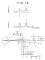
- Figure 1a is a plan view, and Figure 2 a side view, of the construction of the optical system in the ophthalmic measuring apparatus according to the present invention.
- a light projection and observation section 1 is provided with an optical observation system comprised of a condenser lens 12, a pair of lenses 13, a pair of prisms 14, a pair of prisms 15, and a pair of field stops 16.
- the lower part of the optical observation system is linked to a light projection system via a beam splitter 11.
- the light projection system is configured as follows.
- a beam of laser light from a laser light source 5 passes through a lens 6, an optical scanner 7 (such as a galvanometer mirror, for example), a lens 8, an optical scanner 9 (such as a galvanometer mirror, for example), a lens 10, the beam splitter 11 and a condenser lens 12 to converge in the anterior part of the eye being examined at a point of convergence P in front of the crystalline lens L and iris I.
- the light projection system is arranged so that the point of convergence P is deflected vertically and horizontally ( two-dimensionally ) for raster-scanning by means of the optical scanners 7 and 9. This is described below in detail, with reference to Figure 5.
- optical receiving systems 2 and 3 are disposed symmetrically at each side of the light projection and observation section 1.
- Photoelectric converters 21 and 25 of the optical receiving systems 2 and 3 are located at positions that are each a conjugate of the point of convergence P, relative to lenses 19 and 23.
- Disposed in front of the photoelectric converters 21 and 25 are masks 20 and 24 for regulating the size of the detection region. The effect of such an arrangement configuration is that light scattered by floating cells in the anterior chamber of the eye 4 under examination impinges virtually simultaneously on each of the photoelectric converters 21 and 25.
- the outputs of the photoelectric converters 21 and 25 are fed, via an A/D converter means or the like (not shown), into a data processor 100 consisting of a microprocessor, memory and so forth.
- the outputs of the photoelectric converters 21 and 25 are evaluated by the data processor 100, as described later, and the result is output to an output section 101 (which is, for example, a printer, or CRT or liquid crystal display) as the result of the measurement of floating cells in the anterior chamber.
- the data processor 100 also drives the optical scanner 7 via a projected light control section 102 to control the laser-beam scanning of the eye 4 under examination.
- the light projection and observation section 1 is positioned in front of the patient by a known alignment means.
- the examiner uses a pair of eyepieces 17 to observe the region R being scanned in two dimensions by the laser beam passing through the center of the iris of the eye 4 under examination, as illustrated by Figure 5.
- the light projection system is positioned in front of the eye 4 under examination so that the laser beam does not impinge on the iris I and can thus be deflected to maximize the range of the raster-scanning. That is, the size W of the scanned region, as limited by the iris I, is considerably larger when the raster scanning is performed from directly in front of the eye, as shown in Figure 6a, compared to when the scanning is performed from off to one side, as in Figure 6b.
- Other merits of frontal scanning are that movement by the patient is less likely to cause the laser beam to impinge on the iris, observation clearly is facilitated when the observation section is in front of the eye, and alignment is also easier.
- the apparatus shown in Figure 1a and Figure 2 is arranged so that scattered light from the convergence point P of the laser beam in the anterior chamber of the eye 4 under examination is detected from two different directions.
- the data processor 100 only judges pulsed signals that are detected virtually simultaneously by the two optical receiving systems 2 and 3 as being signals produced by floating cells in the anterior chamber. These signals are counted to show the number of such cells and the count integrated is output to the output section 101, as is disclosed in U.S.P No. 4,832,043 or No. 4,838,683 ).
- the light returning to the light-receiving system will also, in addition to the scattered light component, include light reflected by the cornea and noise components generated in the course of the scanning.
- the measurement will be oriented by probability if the measurement volume becomes too small. To reduce a decrease in reproducibility of data, a certain amount of measurement volume is required.
- the method to count cells by the laser beam scattering necessitates that the laser beam be converged to obtain a given level of scattered light intensity. Owing to the highly directional nature of laser light, the result is that directional reflected light is produced by reflection from the front and rear surfaces of the cornea and of the crystalline lens.
- the extensive scanning range would eventually cause this reflected light to enter the light-receiving section.
- Such directional light reflected can be prevented from simultaneously entering both of the light-receiving means, if the light is received from two different directions, which are disposed to be symmetrical with respect to the direction along which the laser beam is projected.
- the light scattered from the floating cells to be measured on the other hand, will be oriented, but not so directional and can simultaneously enter the two light-receiving systems even from the two different directions.
- the laser beam which has passed through the condenser lens 12 and converged at the point of convergence P is raster-scanned in two dimensions by the optical scanners 7 and 9.
- measurement can be carried out using scanning in just one dimension, two-dimensional scanning is preferable because the measurement volume becomes larger.
- two-dimensional scanning is preferable because the measurement volume becomes larger. The following explanation is given only with reference to horizontal scanning, but applies equally well to vertical scanning.
- Figure 3a shows a plan view of the scanning process.
- P′ and P ⁇ to denote the ends of the horizontal raster, the course of the scanning is P ⁇ P′ ⁇ P ⁇ P ⁇ ⁇ P.
- P, P′ and P ⁇ are all arranged so that they come within the anterior chamber.
- optical information simultaneously input into the two light-receiving systems is detected as being information relating to the floating cells to be measured, while optical information input into just one light-receiving system is judged to be noise and is therefore not included in the measurement evaluation.
- This method provides an objective, quantitative measurement of floating cells in the anterior chamber of the patient's eye.
- an effective region is formed by providing an aperture-limiting mask in the vicinity of the image plane: this is termed the mask effect. Light produced outside the effective region is blocked by the mask.
- a single mask (20, 24) is used for the lens (19, 23).
- the effective region is indicated by the blacked-out portion. Light produced in this region can pass unhindered through the mask.
- the shaded portion is a partially effective region from which a certain proportion of light can pass through the mask.
- Noise components can be excluded if the effective region is formed only within the anterior chamber (that is, if the rays that give rise to noise do not come within the effective region), so that signals picked up simultaneously by each of the two light-receiving sections will be originated only from within the anterior chamber.
- the measurement volume is determined by this effective region and the size of the raster scanning region R formed by the two-dimensional scanning shown in Figure 5. If the raster is made larger than the effective region, the effective region itself becomes the measurement volume. A sufficiently large raster can be obtained by using a mydriatic, so the measurement volume may be set by setting the size of the masks 20 and 24, i.e. of the effective region.
- the raster could be projected on the iris, even if a mydriatic is not used.
- the intensity of light scattered by the iris is very high and increases the background noise, the laser beam should preferably not impinge on the iris.
- the size of the masks 20 and 24 and of the raster should be suitably decided in accordance with the requisite measurement volume, taking into account the above factors.
Landscapes
- Life Sciences & Earth Sciences (AREA)
- Health & Medical Sciences (AREA)
- Medical Informatics (AREA)
- Biophysics (AREA)
- Ophthalmology & Optometry (AREA)
- Engineering & Computer Science (AREA)
- Biomedical Technology (AREA)
- Heart & Thoracic Surgery (AREA)
- Physics & Mathematics (AREA)
- Molecular Biology (AREA)
- Surgery (AREA)
- Animal Behavior & Ethology (AREA)
- General Health & Medical Sciences (AREA)
- Public Health (AREA)
- Veterinary Medicine (AREA)
- Eye Examination Apparatus (AREA)
Abstract
An apparatus for opthalmic examination comprises a light projection section (1) directing a laser beam on a selected spot ( P ) in the anterior chamber of the patient's eye ( 4 ). The light scattered from the selected spot is received by photoelectric converters ( 21, 25 ) disposed symmetrically at each side of the light projecting section (1). Signals representing the intensity of the scattered light in the two selected directions (2,3) are then compared to remove noise components, thereby providing an improvement in a S/N ratio. 
Description
- This invention relates to an ophthalmic measuring method and apparatus, and more particularly to an ophthalmic measuring method and apparatus in which an optical system is used to project a laser beam at a selected spot in the camera oculi of a patient's eye, particularly in the anterior chamber thereof, and the laser light scattered therefrom is detected.
- Measurement of floating cells in the anterior chamber is very important in the diagnosis of ophthalmic inflammation and uveitis. Conventionally a slit lamp microscope is often used for this, with grading being via the naked eye, while on the other hand a photographic measuring method has been developed to provide quantitative measurements. However, no method has yet been perfected that is readily applicable to clinical examinations.
- With the conventional method of naked-eye measurement in which judgment can vary depending on the person making the measurement, the data thus gained lacks reliability. One solution has been a method of ophthalmic measurement in which laser light is projected into the eye and the light scattering from the eye is detected and analyzed quantitatively (see, for example, U.S.P No. 4,711,542 ).
- When measuring scattered laser light, light reflecting and scattering from the cornea, the iris, the crystalline lens, including artificial crystalline lenses employed following a white cataract operation, shows up as noise in the scattered laser light and in the measurement site in the anterior chamber, which degrades measurement accuracy, prevents measured values from being reproduced and can cancel out the signal components.
- To overcome this drawbacks, U.S.P No 4,832,043 discloses an ophthalmic disease detection apparatus in which a laser beam is deflected so far as to exceed the slit width formed on a mask in front of a photoelectric converter. In this apparatus, an electric signal derived from the photoelectric converter when the laser beam is deflected outside the slit width is subtracted from an electric signal obtained when the laser beam is deflected within the slit width, thereby removing noise components based on the dark current in the photoelectric converter or unnecessary scattered light or reflected light. Such a method to remove the noise is insufficient because the light scattered or reflected from the cornea or crystalline lens, which behaves itself as noise, has strong dirctivity so that it can directly impinge on the mask, thereby reducing a S/N ratio.
- The object of the present invention is therefore to provide an ophthalmic measuring method and apparatus which enable the noise from reflected or scattered light which may impinge on the spot to be measured in the patient's eye to be reduced, thereby improving the accuracy of the measurement.
- In accordance with the present invention, an ophthalmic measuring method and apparatus is provided in which an optical system is used to project a laser beam at a selected spot in the patient's eye, and the laser light scattered therefrom is detected for ophthalmic measurement. The light scattered from the selected spot is received in at least first and second different directions by a photoelectric converter to produce signals representing the intensity of the scattered light in these directions. The first and second directions are arranged to be symmetrical with respect to the direction along which the laser beam is projected. The signals in the first and second directions are then compared to remove noise components derived from the light reflected at a portion of the eye other than said selected spot in the eye.
- With the above arrangement, the light scattered from the interior of the eye will indeed be oriented, but shows no strong directivity with respect to the angle of incidence, so that this light can simultaneously enter the two light-receiving means from the two different directions. However, owing to the strongly directional nature of the noise component in light reflected by the cornea or artificial crystalline lens, such light containing the noise component will only be able to enter one of the light-receiving means. Therefore, by comparing the signal intensities of the light received from the plurality of directions, it becomes possible to detect only the scattered light that is being used for the measurement in the camera oculi of the patient's eye without any noise component due to the directional light scattered or reflected at a portion other than the spot to be examined.
- The purposes and features of the present invention will become more apparent from a consideration of the following detailed description taken in conjunction with the accompanying drawings in which:
- Figure 1a is an explanatory drawing illustrating the construction of an ophthalmic measuring apparatus according to the present invention;
- Figure 1b is a graph showing the output of the two light-receiving systems;
- Figure 2 is an explanatory drawing showing a side view of the apparatus shown in Figure 1a;
- Figure 3a is an explanatory drawing showing a plan view of the eye being scanned;
- Figures 3b and 3c are graphs each showing the output of the two light-receiving systems and explaining the effect of this invention;
- Figures 4a to 4c are explanatory drawings showing the effect of masks disposed in the light-receiving system;
- Figure 5 is an explanatory drawing showing the image observed by the person conducting the examination; and
- Figures 6a and 6b are drawings illustrating the advantages of front-face scanning.
- This invention is described in detail below on the basis of the preferred embodiments illustrated in the drawings.
- Figure 1a is a plan view, and Figure 2 a side view, of the construction of the optical system in the ophthalmic measuring apparatus according to the present invention.
- With reference to Figure 1a, a light projection and
observation section 1 is provided with an optical observation system comprised of acondenser lens 12, a pair oflenses 13, a pair ofprisms 14, a pair ofprisms 15, and a pair offield stops 16. As shown in Figure 2, the lower part of the optical observation system is linked to a light projection system via abeam splitter 11. - The light projection system is configured as follows. A beam of laser light from a
laser light source 5 passes through alens 6, an optical scanner 7 (such as a galvanometer mirror, for example), alens 8, an optical scanner 9 (such as a galvanometer mirror, for example), alens 10, thebeam splitter 11 and acondenser lens 12 to converge in the anterior part of the eye being examined at a point of convergence P in front of the crystalline lens L and iris I. - The light projection system is arranged so that the point of convergence P is deflected vertically and horizontally ( two-dimensionally ) for raster-scanning by means of the
optical scanners - As the laser beam is deflected, the impingement of the beam on a floating cell in the anterior chamber produces a pulse of scattered light. To evaluate this scattered light,
optical receiving systems observation section 1.Photoelectric converters optical receiving systems lenses photoelectric converters masks eye 4 under examination impinges virtually simultaneously on each of thephotoelectric converters - The outputs of the
photoelectric converters data processor 100 consisting of a microprocessor, memory and so forth. The outputs of thephotoelectric converters data processor 100, as described later, and the result is output to an output section 101 (which is, for example, a printer, or CRT or liquid crystal display) as the result of the measurement of floating cells in the anterior chamber. Thedata processor 100 also drives theoptical scanner 7 via a projectedlight control section 102 to control the laser-beam scanning of theeye 4 under examination. - The light projection and
observation section 1 is positioned in front of the patient by a known alignment means. During this alignment the examiner uses a pair ofeyepieces 17 to observe the region R being scanned in two dimensions by the laser beam passing through the center of the iris of theeye 4 under examination, as illustrated by Figure 5. The light projection system is positioned in front of theeye 4 under examination so that the laser beam does not impinge on the iris I and can thus be deflected to maximize the range of the raster-scanning. That is, the size W of the scanned region, as limited by the iris I, is considerably larger when the raster scanning is performed from directly in front of the eye, as shown in Figure 6a, compared to when the scanning is performed from off to one side, as in Figure 6b. Other merits of frontal scanning are that movement by the patient is less likely to cause the laser beam to impinge on the iris, observation clearly is facilitated when the observation section is in front of the eye, and alignment is also easier. - The operation of the above configuration will now be described, starting with the basic measurement method using the above-described apparatus.
- The apparatus shown in Figure 1a and Figure 2 is arranged so that scattered light from the convergence point P of the laser beam in the anterior chamber of the
eye 4 under examination is detected from two different directions. - In the measurement process, because the laser beam is raster-scanned, the intensity component of the light scattered by floating cells in the anterior chamber appears in the form of pulses, as shown by Figure 1b, producing signals that stand out from the background intensity component B. Therefore, the
data processor 100 only judges pulsed signals that are detected virtually simultaneously by the twooptical receiving systems output section 101, as is disclosed in U.S.P No. 4,832,043 or No. 4,838,683 ). - With respect to the evaluation of the above light-receiving system output, the light returning to the light-receiving system will also, in addition to the scattered light component, include light reflected by the cornea and noise components generated in the course of the scanning. Especially when measuring floating cells in the anterior chamber, the measurement will be oriented by probability if the measurement volume becomes too small. To reduce a decrease in reproducibility of data, a certain amount of measurement volume is required. The method to count cells by the laser beam scattering, on the other hand, necessitates that the laser beam be converged to obtain a given level of scattered light intensity. Owing to the highly directional nature of laser light, the result is that directional reflected light is produced by reflection from the front and rear surfaces of the cornea and of the crystalline lens. In addition, the extensive scanning range would eventually cause this reflected light to enter the light-receiving section. Such directional light reflected can be prevented from simultaneously entering both of the light-receiving means, if the light is received from two different directions, which are disposed to be symmetrical with respect to the direction along which the laser beam is projected. The light scattered from the floating cells to be measured, on the other hand, will be oriented, but not so directional and can simultaneously enter the two light-receiving systems even from the two different directions.
- This will now be explained with reference to Figures 3a to 3c. The laser beam which has passed through the
condenser lens 12 and converged at the point of convergence P is raster-scanned in two dimensions by theoptical scanners - Figure 3a shows a plan view of the scanning process. Using P′ and P˝ to denote the ends of the horizontal raster, the course of the scanning is P → P′→ P → P˝ → P. P, P′ and P˝ are all arranged so that they come within the anterior chamber.
- If the point of convergence is taken as being at P′, light reflected by the cornea advances along the single-arrow broken line. This reflected light indicated by the single-arrow broken line has considerable directivity and luminance because P′ is a point of convergence on which the laser beam is converged. At this time the reflected light passes through the
lens 23 and impinges on thephotoelectric converter 25. If the reflected light impinges directly, a signal will be produced that is far stronger than the signal from floating cells in the anterior chamber. On the other hand, if the reflected light is attenuated by the light-receiving optical system down to around the same strength as the light scattered by cells, it will become impossible to distinguish the reflected light signal from the signal produced by light scattered by cells. However, since the reflected light is strongly directional, it cannot enter theoptical receiving system 2 because it is directed towards theoptical receiving system 3. Similarly, when the point of convergence is at P˝, reflected light indicated by the two-arrow broken line can enter theoptical receiving system 2 but cannot at the same time enter theoptical receiving system 3. The output signal of theoptical receiving system 2 will thus differ from the output signal of theoptical receiving system 3, as shown by Figure 3b. Thus, cell-based scattered light signals can be discriminated from reflected light signals by regarding a signal as being a cell-based signal only when the light concerned enters both light-receiving systems simultaneously. This also applies to the discrimination of cell-based signals from signals originated by the light being reflected by a natural or artificial crystalline lens. - As shown in Figure 3c, when cell-based signals in the output of the
optical receiving system 2 are eclipsed by reflected light or other strong noise components, the harmful light rays can be counted as one pulse because the cell-based scattered light is received in theoptical receiving system 2; when the direction in which the reflecting surface faces is not known, as in the case of an artificial crystalline lens or the like, that is, when the returning light is light reflected by the crystalline lens and has no connection with corneal reflected light, evaluation of the output of the light-receiving systems may be omitted to be on the safe side. While this will result in a lower count, it will not have a major impact. - Thus, optical information simultaneously input into the two light-receiving systems is detected as being information relating to the floating cells to be measured, while optical information input into just one light-receiving system is judged to be noise and is therefore not included in the measurement evaluation. This method provides an objective, quantitative measurement of floating cells in the anterior chamber of the patient's eye.
- The effect of providing the
masks photoelectric converters optical receiving system 2 will now be explained. - In general, an effective region is formed by providing an aperture-limiting mask in the vicinity of the image plane: this is termed the mask effect. Light produced outside the effective region is blocked by the mask.
- In the example shown in Figure 4b, a single mask (20, 24) is used for the lens (19, 23). In the figure, the effective region is indicated by the blacked-out portion. Light produced in this region can pass unhindered through the mask. The shaded portion is a partially effective region from which a certain proportion of light can pass through the mask. In the case of the present invention there are two light-receiving sections, which are provided with
respective masks - Here, Figure 4c shows when α = β = 45°. Noise components can be excluded if the effective region is formed only within the anterior chamber ( that is, if the rays that give rise to noise do not come within the effective region), so that signals picked up simultaneously by each of the two light-receiving sections will be originated only from within the anterior chamber.
- The measurement volume is determined by this effective region and the size of the raster scanning region R formed by the two-dimensional scanning shown in Figure 5. If the raster is made larger than the effective region, the effective region itself becomes the measurement volume. A sufficiently large raster can be obtained by using a mydriatic, so the measurement volume may be set by setting the size of the
masks - As long as the iris does not come within the effective region, the raster could be projected on the iris, even if a mydriatic is not used. However, because the intensity of light scattered by the iris is very high and increases the background noise, the laser beam should preferably not impinge on the iris. Thus, when measurements are being carried out without using a mydriatic, the size of the
masks - While the invention has been described with reference to a preferred embodiment, it will be understood by those skilled in the art that various changes may be made and equivalents may be substituted for elements thereof without departing from the scope of the invention. In addition, many modifications may be made to adapt a particular situation or material to the teachings of the invention without departing from the essential scope thereof. Therefore, it is intended that the invention should not be limited to the particular embodiment disclosed as the best mode contemplated for carrying out the invention, but that the invention will include all embodiments falling within the scope of the appended claims.
Claims (11)
1. An ophthalmic measuring method in which an optical system is used to project a laser beam at a selected spot ( P ) in the camera oculi of the patient's eye ( 4 ), and the laser light scattered therefrom is detected by a photoelectric converter for ophthalmic measurement, characterized in that the scattered light is received in a first direction ( 2 ) by means of a photoelectric converter ( 21 ) to produce a signal representing the intensity of the scattered light in the first direction and in a second direction ( 3 ) by means of a photoelectric converter ( 25 ) to produce a signal representing the intensity of the scattered light in the second direction with said first and second directions being arranged to be symmetrical with respect to the direction along which the laser beam is projected at the selected spot in the eye, and that the signals are compared in the first and second directions to remove a noise signal derived from the light reflected at a portion ( L ) of the eye other than said selected spot in the eye.
2. A method as set forth in claim 1, wherein the laser beam is deflected horizontally and vertically to scan the selected spot two-dimensionally ( R ).
3. A method as set forth in claim 1, wherein the noise signal is derived from the light reflected at the cornea or crystalline lens ( L ) in the eye.
4. A method as set forth in claim 1, wherein the laser beam is projected at the selected spot in the eye from the front side of the eye to be examined.
5. An ophthalmic measuring method in which an optical system is used to project a laser beam at a selected spot ( P ) in the camera oculi of the patient's eye ( 4 ) by means of a laser beam projector ( 1 ), and the laser light scattered therefrom is detected by a photoelectric converter for ophthalmic measurement, characterized in:
- that first light-receiving means ( 2 ) are provided in a first direction with respect to the laser beam projector and equipped with a photoelectric converter ( 21 ) for receiving light scattered from the selected spot ( P ) in the camera oculi of the eye to produce a signal representing the intensity of the scattered light in the first direction,
- that second light-receiving means ( 3 ) are provided in a second direction with respect to the laser beam projector ( 1 ) and equipped with a photoelectric converter ( 25 ) for receiving light scattered from the selected spot in the camera oculi of the eye to produce a signal representing the intensity of the scattered light in the second direction, said first and second light-receiving means ( 2, 3 ) being disposed symmetrically at each side of the laser beam projector ( 1 ),
- and that means ( 100 ) are provided for processing the signals obtained from the first and second light-receiving means to compare them and remove a noise signal derived from the light reflected at a portion of the eye other than the selected spot in the eye.
6. An apparatus as set forth in claim 5, further comprising means ( 7, 9 ) for deflecting the laser beam horizontally and vertically to scan the spot to be measured two-dimensionally.
7. An apparatus as set forth in claim 5, further comprising an optical observation system ( 1 ) for observing the state of the laser beam projection.
8. An apparatus as set forth in claim 5, wherein the laser beam projector ( 1 ) is disposed in the vicinity of the front of the eye to be examined.
9. An apparatus as set forth in claim 7, wherein the optical observation system ( 1 ) is disposed in the vicinity of the front of the eye to be examined.
10. An apparatus as set forth in claim 9, wherein the laser light projector ( 1 ) and at least the portion of the optical observation system ( 1 ) are integrated.
11. An apparatus as set forth in claim 5, wherein an optical mask ( 20, 24 ) is disposed in front of the photoelectric converter in the first and second light-receiving means, respectively, to define a measurement region corresponding to the shape of the optical mask.
Applications Claiming Priority (2)
| Application Number | Priority Date | Filing Date | Title |
|---|---|---|---|
| JP270699/88 | 1988-10-28 | ||
| JP63270699A JPH02119837A (en) | 1988-10-28 | 1988-10-28 | Method and device for ophthalmologic measurement |
Publications (1)
| Publication Number | Publication Date |
|---|---|
| EP0366421A1 true EP0366421A1 (en) | 1990-05-02 |
Family
ID=17489728
Family Applications (1)
| Application Number | Title | Priority Date | Filing Date |
|---|---|---|---|
| EP89310965A Withdrawn EP0366421A1 (en) | 1988-10-28 | 1989-10-24 | Ophtalmic measuring method and apparatus |
Country Status (3)
| Country | Link |
|---|---|
| US (1) | US5120123A (en) |
| EP (1) | EP0366421A1 (en) |
| JP (1) | JPH02119837A (en) |
Cited By (2)
| Publication number | Priority date | Publication date | Assignee | Title |
|---|---|---|---|---|
| NL1024232C2 (en) * | 2003-09-05 | 2005-03-08 | Konink Nl Akademie Van Wetensc | Method and device for measuring retinal stray light. |
| GB2422660A (en) * | 2005-01-27 | 2006-08-02 | Christopher Glynn | Device for monitoring body functions |
Families Citing this family (8)
| Publication number | Priority date | Publication date | Assignee | Title |
|---|---|---|---|---|
| US5203328A (en) * | 1991-07-17 | 1993-04-20 | Georgia Tech Research Corporation | Apparatus and methods for quantitatively measuring molecular changes in the ocular lens |
| NL9200071A (en) * | 1992-01-15 | 1993-08-02 | Stichting Science Park Maastri | DEVICE FOR DETERMINING THE TOPOGRAPHY OF A CURVED SURFACE. |
| JP2965101B2 (en) * | 1992-07-31 | 1999-10-18 | 株式会社ニデック | Ophthalmic equipment |
| US5355895A (en) * | 1993-07-20 | 1994-10-18 | Hay S Hutson | Ocular disease detection apparatus |
| US5526113A (en) * | 1994-06-21 | 1996-06-11 | Honeywell Inc. | Method and apparatus for measurement of spatial signal and noise power of imaging systems |
| JP6077777B2 (en) * | 2012-07-30 | 2017-02-08 | キヤノン株式会社 | Ophthalmic apparatus and alignment method of ophthalmic apparatus |
| JP6071304B2 (en) | 2012-07-30 | 2017-02-01 | キヤノン株式会社 | Ophthalmic apparatus and alignment method |
| US10582852B2 (en) | 2015-02-05 | 2020-03-10 | Carl Zeiss Meditec Ag | Method and apparatus for reducing scattered light in broad-line fundus imaging |
Citations (2)
| Publication number | Priority date | Publication date | Assignee | Title |
|---|---|---|---|---|
| WO1986002249A1 (en) * | 1984-10-18 | 1986-04-24 | Kerascan, Inc. | Scanning keratometers |
| US4761071A (en) * | 1984-11-06 | 1988-08-02 | Baron William S | Apparatus and method for determining corneal and scleral topography |
Family Cites Families (4)
| Publication number | Priority date | Publication date | Assignee | Title |
|---|---|---|---|---|
| US4516641A (en) * | 1983-10-17 | 1985-05-14 | Hughes Tool Company-Usa | Earth boring bit with pressure compensating rigid face seal |
| JPS63135128A (en) * | 1986-11-27 | 1988-06-07 | 興和株式会社 | Ophthalmic measuring apparatus |
| JP2618912B2 (en) * | 1987-08-31 | 1997-06-11 | 興和株式会社 | Fundus examination device |
| JP2794698B2 (en) * | 1987-10-28 | 1998-09-10 | 興和 株式会社 | 3D shape measuring device |
-
1988
- 1988-10-28 JP JP63270699A patent/JPH02119837A/en active Pending
-
1989
- 1989-10-24 EP EP89310965A patent/EP0366421A1/en not_active Withdrawn
- 1989-10-25 US US07/427,039 patent/US5120123A/en not_active Expired - Fee Related
Patent Citations (2)
| Publication number | Priority date | Publication date | Assignee | Title |
|---|---|---|---|---|
| WO1986002249A1 (en) * | 1984-10-18 | 1986-04-24 | Kerascan, Inc. | Scanning keratometers |
| US4761071A (en) * | 1984-11-06 | 1988-08-02 | Baron William S | Apparatus and method for determining corneal and scleral topography |
Cited By (5)
| Publication number | Priority date | Publication date | Assignee | Title |
|---|---|---|---|---|
| NL1024232C2 (en) * | 2003-09-05 | 2005-03-08 | Konink Nl Akademie Van Wetensc | Method and device for measuring retinal stray light. |
| WO2005023103A1 (en) * | 2003-09-05 | 2005-03-17 | Koninklijke Nederlandse Akademie Van Wetenschappen | Method and device for measuring retinal stray light |
| US7673991B2 (en) | 2003-09-05 | 2010-03-09 | Koninklijke Nederlandse Akademie Van Wetenschappen | Method and device for measuring retinal stray light |
| GB2422660A (en) * | 2005-01-27 | 2006-08-02 | Christopher Glynn | Device for monitoring body functions |
| GB2422660B (en) * | 2005-01-27 | 2008-12-03 | Christopher Glynn | Improved device for monitoring body functions |
Also Published As
| Publication number | Publication date |
|---|---|
| US5120123A (en) | 1992-06-09 |
| JPH02119837A (en) | 1990-05-07 |
Similar Documents
| Publication | Publication Date | Title |
|---|---|---|
| EP0295764B1 (en) | Ophthalmic disease detection apparatus | |
| JP2794698B2 (en) | 3D shape measuring device | |
| EP0392743B1 (en) | Ophthalmological measurement method and apparatus | |
| US4832043A (en) | Ophthalmic disease detection apparatus | |
| JPH0571931A (en) | Solid shape measuring device | |
| US5120123A (en) | Ophthalmic measuring method and apparatus | |
| US5202709A (en) | Ophthalmological alignment and measurement apparatus | |
| US5184157A (en) | Ophthalmic measurement apparatus | |
| US4950068A (en) | Ophthalmic disease detection apparatus | |
| US5000562A (en) | Ophthalmic disease detection method and apparatus | |
| EP0513970A2 (en) | Ophthalmic measurement apparatus | |
| US4941741A (en) | Ophthalmic disease detection apparatus | |
| EP0469770A1 (en) | Ophthalmological measurement apparatus | |
| EP0376470B1 (en) | Ophthalmic measuring apparatus | |
| EP0380260A2 (en) | Ophthalmic measurement apparatus | |
| US4988184A (en) | Ophthalmic disease detection apparatus | |
| JPH09236407A (en) | Solid geometry measuring device | |
| JP3608854B2 (en) | Ophthalmic measuring device | |
| JP4235504B2 (en) | Ophthalmic measuring device | |
| JP2688231B2 (en) | Ophthalmic measurement device | |
| JP2557394B2 (en) | Ophthalmic measuring device | |
| JP3437230B2 (en) | Fundus blood flow meter | |
| JP2968540B2 (en) | Ophthalmic equipment | |
| JP4035247B2 (en) | Fundus blood flow meter | |
| JP2005102938A (en) | Ophthalmological measuring device and positioning method |
Legal Events
| Date | Code | Title | Description |
|---|---|---|---|
| PUAI | Public reference made under article 153(3) epc to a published international application that has entered the european phase |
Free format text: ORIGINAL CODE: 0009012 |
|
| AK | Designated contracting states |
Kind code of ref document: A1 Designated state(s): CH DE FR GB IT LI |
|
| 17P | Request for examination filed |
Effective date: 19901015 |
|
| 17Q | First examination report despatched |
Effective date: 19930121 |
|
| STAA | Information on the status of an ep patent application or granted ep patent |
Free format text: STATUS: THE APPLICATION IS DEEMED TO BE WITHDRAWN |
|
| 18D | Application deemed to be withdrawn |
Effective date: 19930602 |