EP0366406A2 - Vielfach-Hochfrequenz-Radarbetrieb mit einem einzigen Empfänger - Google Patents
Vielfach-Hochfrequenz-Radarbetrieb mit einem einzigen Empfänger Download PDFInfo
- Publication number
- EP0366406A2 EP0366406A2 EP89310937A EP89310937A EP0366406A2 EP 0366406 A2 EP0366406 A2 EP 0366406A2 EP 89310937 A EP89310937 A EP 89310937A EP 89310937 A EP89310937 A EP 89310937A EP 0366406 A2 EP0366406 A2 EP 0366406A2
- Authority
- EP
- European Patent Office
- Prior art keywords
- internal
- pulses
- transmit
- repeating sequence
- frequency
- Prior art date
- Legal status (The legal status is an assumption and is not a legal conclusion. Google has not performed a legal analysis and makes no representation as to the accuracy of the status listed.)
- Withdrawn
Links
Images
Classifications
-
- G—PHYSICS
- G01—MEASURING; TESTING
- G01S—RADIO DIRECTION-FINDING; RADIO NAVIGATION; DETERMINING DISTANCE OR VELOCITY BY USE OF RADIO WAVES; LOCATING OR PRESENCE-DETECTING BY USE OF THE REFLECTION OR RERADIATION OF RADIO WAVES; ANALOGOUS ARRANGEMENTS USING OTHER WAVES
- G01S13/00—Systems using the reflection or reradiation of radio waves, e.g. radar systems; Analogous systems using reflection or reradiation of waves whose nature or wavelength is irrelevant or unspecified
- G01S13/02—Systems using reflection of radio waves, e.g. primary radar systems; Analogous systems
- G01S13/06—Systems determining position data of a target
- G01S13/08—Systems for measuring distance only
- G01S13/10—Systems for measuring distance only using transmission of interrupted, pulse modulated waves
- G01S13/24—Systems for measuring distance only using transmission of interrupted, pulse modulated waves using frequency agility of carrier wave
Definitions
- the disclosed invention generally relates to a pulse radar system, and is more particularly directed to a pulse radar system that utilizes a plurality of RF frequencies with a single receiver.
- the transmitted signal comprises a pulse modulated radio frequency (RF) carrier signal.
- the pulse repetition frequency (PRF) will depend primarily on the maximum range at which targets are expected since for a given pulse emitted, any corresponding return signal should be received during the receive interval prior to the next pulse in order to avoid ambiguities. In other words, if the pulse repetition rate is too high, the likelihood of receiving target echoes from the wrong pulse transmission (multiple-time-around echoes) is increased.
- pulse repetition frequencies are reduced with increasing maximum expected range. For applications where the range of interest is further away, for example greater than 40 nautical miles, low pulse repetition rates are utilized and only a small portion of the receive interval is useful. The remaining portion of the receive interval is waiting time that is not utilized.
- a known technique for utilizing otherwise non-useful waiting time of the receive interval utilizes a plurality of respectively associated receivers and fixed frequency RF exciters (i.e., each receiver is responsive only to a specific fixed frequency exciter) to permit simultaneous transmit and receive of different frequencies. Performance is improved, but at the cost of additional hardware and complexity.
- Performance can also be improved by increasing transmission power. However, this requires larger power supplies, increased power handling capabilities, and in certain applications produces an unwanted increase in interception.
- Another advantage would be to provide a pulse radar system which provides increased signal to noise ratio without increasing transmission power.
- a radar system that includes a circuit for generating a repeating sequence of internal pulses of RF energy of different frequencies.
- a transmit circuit responsive to the internal pulses of RF energy generates a transmit radar signal comprising a transmit repeating sequence of transmit intervals during which pulses of RF energy are transmitted.
- a single receiver responsive to the repeating sequence of internal RF pulses receives radar return signals based on all of the RF frequencies in a receive repeating sequence of receive intervals which do not occur at the same time as the transmit intervals
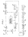
- FIG. 1 shown therein is a block diagram of a pulse radar system 10 having a multiple frequency RF exciter 11 which provides an RF output that is switched between different frequencies.
- the output of the multiple frequency RF exciter 11, which will be described more fully herein, is provided to an RF transmit amplifier 13.
- the output of the transmit amplifier 13 is coupled to a circulator 17 via a transmit switch 15.
- the circulator 17 is a known circuit which includes an antenna port and a receive port in addition to the transmit port. It directs signals on the transmit port to an antenna 19 coupled to the antenna port, and directs signals received by the antenna to the receiver port.
- the receive port of the circulator 17 is coupled to one input of a mixer 23 via a receive switch 21.
- the other input of the mixer 23 receives the output of a mixer 25.
- the inputs to the mixer 25 are provided by the RF exciter 11 and an IF oscillator 27 which provides the intermediate frequency (IF) carrier signal IF c .
- the circulator 17 does not provide sufficient isolation and protection of the radar receiver circuitry (i.e., the circuitry downstream of the receive switch 21) from the transmit signal to the transmit port of the circulator 17.
- additional receiver protection circuitry of known configuration would be utilized in the implementation of the radar system 10.
- the receive switch 21 would be incorporated in that receiver protection circuitry.
- the transmit switch 15 is closed for transmission and is otherwise open.
- the receive switch 21 is closed when the transmit switch 15 is open.
- the transmit switch 15 is in position T (for transmit) when it is closed, and is in position R (for receive) when it is open.
- the receive switch 21 is in the position R when it is closed, and in the position T when it is open.
- the switches 15, 21 comprise very fast switches as are utilized in present radar systems, and for practical purposes, one of the switches is closed at any given point in time.
- the output of the mixer 23 is connected to a band-pass filter 29 which provides its output to one input of a mixer 31.
- the other input of the mixer 31 receives the IF carrier signal IF c provided by the IF oscillator 27.
- the output of the mixer 31 is provided to a low pass filter 33 whose output is coupled to the input of an analog-to-digital (A/D) converter 35 which provides digital samples of the received radar signals.
- a processor 37 which can be microprocessor based, processes the digital samples and provides the processed outputs to a display apparatus 39 which can be a video display or a plotter, for example.
- the foregoing radar system 10 departs from known systems in the use of multiple RF frequencies and the single receiver processing of the received radar signals.
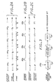
- FIG. 2A shown therein is a timing diagram showing, by way of illustrative example, the use of two (2) RF frequencies denominated RF A and RF B which are alternately provided by the RF exciter 11 for respective time intervals, which can be equal or unequal.
- the first RF frequency RF A is provided during the time interval T A
- the second RF frequency RF B is provided during the time interval T B .
- the RF exciter provides a repeating sequence of pulses of two different RF frequencies.
- each of the time intervals T A , T B is allocated into sequential subintervals respectively identified as settling time T s , receive time T r , and transmit time T t .
- the settling time T s occurs after the RF exciter switches to the frequency RF A and defines the time when the output of the RF exciter settles to the new RF frequency.
- the receive time T r follows and defines the time when return echoes can be received from the transmission which occurred during the prior time interval T A .
- the transmit time T t defines the time when the radar system is transmitting a pulse of the frequency RF A .
- the receive switch 21 is closed during the settling time and receive time subintervals, and is open during the transmit time subinterval.
- the transmit switch 15 is open during the settling and receive subintervals, and is closed during the transmit subinterval.
- the operation during the time interval T B is substantially identical except that the output of the exciter circuit 11 is the frequency RF B .
- FIG. 2B schematically illustrates the transmitted output of the radar system 10 which includes alternating pulses of RF energy of the two frequencies RF A and RF B .
- the transmitted output can be considered as the interleaving of two pulse trains having the same periodicity, wherein each pulse train comprises pulses of RF energy of one of the RF frequencies.
- the radar system 10 transmits a pulse of a given RF frequency while waiting for the return signal from the prior pulse of a different RF frequency.
- FIG. 2C shows the positions of the transmit switch 15 and the receive switch 21 for given subintervals of the time intervals T A and T B . It should be recalled that the T and R positions of the transmit and receive switches are reversed as between them. Thus, position R for the transmit switch means that it is open while position R for the receive switch means that it is closed.
- signals received during the receive interval T r of a given time interval associated with a given frequency are the result of the pulse of RF energy that was transmitted during the immediately prior time interval for that frequency (T A in this example). Since the time relation between a given receive subinterval and its corresponding transmitted pulse is fixed, each output of the A/D converter 35 has a known time delay associated with it. Since range bins are based on time delay, each output of the A/D converter 35 has a known range bin associated therewith and each output of the A/D converter 35 has a particular RF frequency associated with it.
- Known circuitry, including resettable counters for example, in the processor 37 is utilized to associate the received signal samples with the appropriate RF frequencies and range bins.
- the processor 37 receives the received signal samples and associates the received samples with the appropriate range bins without regard for RF frequency. In other words, only time delay is recognized. For each range bin, a predetermined number of received signal samples is integrated, and the integration result is provided to the display apparatus 39.
- the received signal samples provided by the A/D converter 35 can be stored in different memories respectively associated with the different frequencies, and then integrated separately for a given integration period.
- the integrated data for each range bin are added to provide a combined output.
- the RF exciter 11 must provide for each frequency coherence between the intervals associated with such frequency. In other words, when the output of the RF exciter 11 switches for example from RF B to RF A and then to RF B , the waveform of the later occurring RF B must be of the same phase that would have occurred if the switch to RF A had not occurred. The output intervals for RF A must also have the same phase relations. Generally stated, for each RF frequency, the phase of the output of the RF exciter 11 must be predictable.
- the RF exciter 11 can comprise a phase locked loop that includes a free running reference oscillator that can be switched from one harmonic to another without switching to a different crystal. In other words, within the reference oscillator each harmonic behaves as if it were not interrupted.
- in-phase and quadrature components must be determined.
- a mixer 31′, a low pass filter 33′, and an A/D converter 35 would be connected in parallel with the mixer 31, low pass filter 33, and A/D converter 35 of FIG. 1.
- the output of the bandpass filter 29 is provided to one of the inputs of the mixer 31′ which at its other input receives an IF carrier signal IF c′ which is a version of the IF carrier signal IF c (provided to the mixer 31) that is 90 degrees out of phase relative thereto.
- the A/D converter 35′ provides the quadrature components while the A/D converter 35 provides the in-phase components.
- the processor 37 can integrate the received signal samples for each RF frequency separately for each range bin. That is, the in-phase and quadrature components for each frequency for each range bin are integrated separately. The respective integrated data (in-phase and quadrature) for each frequency for each range bin are then added to provide a combined output for each range bin. Magnitude is then calculated from the in-phase and quadrature components for each range bin or range-bit doppler cell (for coherent processing), which is provided to the display 39.
- the in-phase and quadrature components of each received signal sample can be utilized to obtain the magnitude of such sample which is then processed non-coherently as discussed above.
- the disclosed invention contemplates multiple RF frequencies in a predetermined sequence that is continually repeated.
- the RF exciter could provide a repeating sequence of pulses of three (3) RF frequencies RF A , RF B , RF C during three sequential time intervals T A , T B , T C , which can be of equal or unequal duration. Each interval would have settling time, receive, and transmit intervals as described above.
- the transmitted output of the N frequency radar can be considered as the interleaving of N pulse trains of the same periodicity wherein each pulse train includes pulses of RF energy of one of the RF frequencies.
- the invention more generally contemplates multiple RF frequencies wherein the receive and transmit intervals for a given frequency do not have to be adjacent.
- the invention generally contemplates a repeating sequence of interleaved receive and transmit interval pairs for each of a plurality of different frequencies, where the receive and transmit interval pair for a given RF frequency do not have to be adjacent.
- the above described two and three frequency radars are examples of adjacent transmit and receive interval pairs for each frequency.
- the transmit and receive repeating sequence could be: Receive RF A Transmit RF B Receive RF C Transmit RF A Receive RF B Transmit RF C
- the intervals during which a given RF frequency is provided by the RF exciter is controlled so as to provide the appropriate RF frequency for an appropriate time interval.
- the RF exciter would provide a given RF frequency output for only a short time as needed for settling time and transmit time. The receive intervals would be longer.
- the disclosed radar system provides for a repeating sequence of internal RF pulses provided by the RF exciter, a transmit repeating sequence and a receive repeating sequence.
- the repeating sequence of RF pulses provided by the exciter is (RF A ,RF B ,RF C ,RF A , RF B ,RF C ).
- the transmit interval repeating sequence in terms of RF frequency is (RF B , RF A , RF C ) and the receive interval repeating sequence in terms of RF frequency is (RF A ,RF C ,RF B ).
- Transmit and receive intervals do not occur at the same time, and interleaving of the transmit and receive interval sequences defines the repeating sequence of RF pulses provided by the RF exciter.
- the repeating sequence of RF pulses provided by the RF exciter is (RF A ,RF B , RF C ), where each pulse of a given frequency is utilized for one receive interval and one transmit interval for that frequency.
- the transmit interval repeating sequence is (RF A , RF B ,RF C ) and the receive interval repeating sequence is (RF A , RF B , RF C ).
- Transmit and receive intervals do not occur at the same time, and interleaving the transmit and receive interval sequences produces the sequence (RF A ,RF A ,RF B ,RF B ,RF C ,RF C ), which defines the repeating sequence of RF pulses (RF A , RF B ,RF C ) provided by the RF exciter since each RF pulse of the exciter is used for a receive interval and a transmit interval.
- the RF exciter rather than providing two adjacent pulses of RF energy at the same frequency, the RF exciter provides one pulse of RF energy for each occurrence of adjacent receive and transmit intervals of a given frequency.
- the foregoing has been a disclosure of a pulse radar system having multiple RF frequencies and a single receiver, and wherein only one internal RF frequency is present in the system at any given time.
- the use of multiple frequencies provides for increased signal-to-noise ratio, which allows for longer detection ranges and/or increased visibility of targets as compared to a single frequency radar at the same peak transmit power.
- the same signal-to-noise ratio is achieved at a lesser peak transmit power as compared to a single frequency radar.
- multiple RF frequencies reduce speckle, which is particularly advantageous for synthetic aperture radar.
- the reduced peak transmit power reduces the probability of interception, which is advantageous in certain military applications, as is the improved performance against electronic countermeasures resulting from the use of multiple frequencies.
- the multiple frequency radar of the invention cannot be used for high pulse repetition frequencies, for example, above 100 KHz, but such systems already have higher signal-to-noise ratios in comparison to low pulse repetition frequency radar by virtue of higher duty factors and shorter ranges.
- This invention will, however, somewhat reduce the need to go to a higher pulse repetition rate by providing a higher duty factor with a lower pulse repetition rate.
Landscapes
- Engineering & Computer Science (AREA)
- Radar, Positioning & Navigation (AREA)
- Remote Sensing (AREA)
- Computer Networks & Wireless Communication (AREA)
- Physics & Mathematics (AREA)
- General Physics & Mathematics (AREA)
- Radar Systems Or Details Thereof (AREA)
Applications Claiming Priority (2)
| Application Number | Priority Date | Filing Date | Title |
|---|---|---|---|
| US07/262,917 US4926185A (en) | 1988-10-26 | 1988-10-26 | Multiple radio frequency single receiver radar operation |
| US262917 | 1988-10-26 |
Publications (2)
| Publication Number | Publication Date |
|---|---|
| EP0366406A2 true EP0366406A2 (de) | 1990-05-02 |
| EP0366406A3 EP0366406A3 (de) | 1991-05-15 |
Family
ID=22999626
Family Applications (1)
| Application Number | Title | Priority Date | Filing Date |
|---|---|---|---|
| EP19890310937 Withdrawn EP0366406A3 (de) | 1988-10-26 | 1989-10-24 | Vielfach-Hochfrequenz-Radarbetrieb mit einem einzigen Empfänger |
Country Status (4)
| Country | Link |
|---|---|
| US (1) | US4926185A (de) |
| EP (1) | EP0366406A3 (de) |
| JP (1) | JPH02179490A (de) |
| AU (1) | AU610440B2 (de) |
Cited By (2)
| Publication number | Priority date | Publication date | Assignee | Title |
|---|---|---|---|---|
| EP0706061A3 (de) * | 1994-10-04 | 1996-04-24 | Ericsson Telefon Ab L M | |
| CN109212487A (zh) * | 2018-09-27 | 2019-01-15 | 芜湖博高光电科技股份有限公司 | 一种双频段一体的tr组件 |
Families Citing this family (18)
| Publication number | Priority date | Publication date | Assignee | Title |
|---|---|---|---|---|
| US5552793A (en) * | 1994-12-02 | 1996-09-03 | Hughes Missile Systems Company | Self calibrated act pulse compression system |
| US6714157B2 (en) | 2002-08-02 | 2004-03-30 | The Boeing Company | Multiple time-interleaved radar operation using a single radar at different angles |
| US20060238742A1 (en) * | 2005-04-25 | 2006-10-26 | Hunt Jeffrey H | Short duty cycle lidar |
| JP2007170846A (ja) * | 2005-12-19 | 2007-07-05 | Toshiba Corp | レーダ装置 |
| JP2008002811A (ja) * | 2006-06-20 | 2008-01-10 | Daido Signal Co Ltd | 近距離測定用パルスレーダ装置 |
| DE102007010236B4 (de) * | 2007-03-02 | 2008-11-20 | Toposys Topographische Systemdaten Gmbh | Vorrichtung und Verfahren zur Entfernungsbestimmung mittels Lichtpulsen |
| FR2968771B1 (fr) * | 2010-12-10 | 2012-12-28 | Thales Sa | Equipement et procede optique de telemetrie et de communication haut debit |
| IL250253B (en) | 2017-01-24 | 2021-10-31 | Arbe Robotics Ltd | A method for separating targets and echoes from noise, in radar signals |
| IL255982A (en) | 2017-11-29 | 2018-01-31 | Arbe Robotics Ltd | Detection, mitigation and prevention of mutual interference between fixed water radars in vehicles |
| IL259190A (en) | 2018-05-07 | 2018-06-28 | Arbe Robotics Ltd | System and method of fmcw time multiplexed mimo imaging radar using multi-band chirps |
| IL260696A (en) | 2018-07-19 | 2019-01-31 | Arbe Robotics Ltd | Method and device for structured self-testing of radio frequencies in a radar system |
| IL260695A (en) * | 2018-07-19 | 2019-01-31 | Arbe Robotics Ltd | Method and device for eliminating waiting times in a radar system |
| IL260694A (en) | 2018-07-19 | 2019-01-31 | Arbe Robotics Ltd | Method and device for two-stage signal processing in a radar system |
| IL261636A (en) | 2018-09-05 | 2018-10-31 | Arbe Robotics Ltd | Deflected MIMO antenna array for vehicle imaging radars |
| US11255900B2 (en) * | 2019-10-30 | 2022-02-22 | Keysight Technologies, Inc. | System and method for measuring repetitive complex and pulse modulated RF signals |
| IL271269A (en) | 2019-12-09 | 2021-06-30 | Arbe Robotics Ltd | Radom for a planar antenna for car radar |
| US10915717B1 (en) * | 2020-04-23 | 2021-02-09 | Avid Identification Systems, Inc. | Muting circuit for analog filters in radio frequency identification (RFID) systems |
| IL278587A (en) | 2020-11-09 | 2022-06-01 | Arbe Robotics Ltd | Estimating an efficient direction of arrival using a low degree approximation |
Family Cites Families (10)
| Publication number | Priority date | Publication date | Assignee | Title |
|---|---|---|---|---|
| US2817832A (en) * | 1951-02-02 | 1957-12-24 | Robert H Mathes | Multiple sweep |
| US3390391A (en) * | 1965-11-05 | 1968-06-25 | Philips Corp | Radar system employing variable frequency pulses |
| US3566408A (en) * | 1969-02-26 | 1971-02-23 | Avco Corp | Method of and apparatus for three color-echo ranging |
| FR2201476B1 (de) * | 1972-09-26 | 1977-07-29 | Thomson Csf | |
| FR2220797B1 (de) * | 1973-03-06 | 1977-09-02 | Thomson Csf | |
| US4197540A (en) * | 1977-04-27 | 1980-04-08 | Hughes Aircraft Company | Simultaneous transmit and receive radar subsystem |
| GB2044571A (en) * | 1979-03-17 | 1980-10-15 | Marconi Co Ltd | Pulse radar system |
| DE3175683D1 (en) * | 1980-09-27 | 1987-01-15 | Marconi Co Ltd | Radar apparatus |
| JPS60170774A (ja) * | 1984-02-15 | 1985-09-04 | Natl Space Dev Agency Japan<Nasda> | 合成開口レ−ダ |
| IT1206287B (it) * | 1987-05-26 | 1989-04-14 | Selenia Ind Elettroniche | La detezione e il riconoscimento di radar con agilita' di frequenza da bersagli di traccia multipla impulso a impulso, utilizzato per |
-
1988
- 1988-10-26 US US07/262,917 patent/US4926185A/en not_active Expired - Fee Related
-
1989
- 1989-10-19 AU AU43531/89A patent/AU610440B2/en not_active Ceased
- 1989-10-24 EP EP19890310937 patent/EP0366406A3/de not_active Withdrawn
- 1989-10-26 JP JP1277348A patent/JPH02179490A/ja active Pending
Cited By (3)
| Publication number | Priority date | Publication date | Assignee | Title |
|---|---|---|---|---|
| EP0706061A3 (de) * | 1994-10-04 | 1996-04-24 | Ericsson Telefon Ab L M | |
| US5598165A (en) * | 1994-10-04 | 1997-01-28 | Telefonaktiebolaget Lm Ericsson | Method for the control of a radar station |
| CN109212487A (zh) * | 2018-09-27 | 2019-01-15 | 芜湖博高光电科技股份有限公司 | 一种双频段一体的tr组件 |
Also Published As
| Publication number | Publication date |
|---|---|
| JPH02179490A (ja) | 1990-07-12 |
| AU4353189A (en) | 1990-05-31 |
| US4926185A (en) | 1990-05-15 |
| AU610440B2 (en) | 1991-05-16 |
| EP0366406A3 (de) | 1991-05-15 |
Similar Documents
| Publication | Publication Date | Title |
|---|---|---|
| US4926185A (en) | Multiple radio frequency single receiver radar operation | |
| US5376939A (en) | Dual-frequency, complementary-sequence pulse radar | |
| US5784026A (en) | Radar detection of accelerating airborne targets | |
| US4219812A (en) | Range-gated pulse doppler radar system | |
| US5646623A (en) | Coherent, frequency multiplexed radar | |
| US5151702A (en) | Complementary-sequence pulse radar with matched filtering following doppler filtering | |
| US5440311A (en) | Complementary-sequence pulse radar with matched filtering and Doppler tolerant sidelobe suppression preceding Doppler filtering | |
| US4388622A (en) | Double sideband linear frequency modulation system for radar applications | |
| US3680105A (en) | Pulse compression radar system | |
| US5999119A (en) | CW radar range measuring system with improved range resolution | |
| US5309160A (en) | Radar system and method having variable tracking range | |
| EP0389720B1 (de) | Radargerät, das Ziele in naher und weiter Entfernung erfasst | |
| EP0292556B1 (de) | Im frequenzbereich wirkendes impulsraffungsradargerät zur störechobeseitigung | |
| US3878525A (en) | Frequency jumping CW radar | |
| US5140332A (en) | Short pulse radar system with a long pulse transmitter | |
| US4292635A (en) | Signal processing system | |
| US5389931A (en) | Radar signal processing system | |
| US5422646A (en) | High frequency MTI radar | |
| EP0322017B1 (de) | Radargerät unter Verwendung von verschiedener Arten von Impulsen | |
| US5339084A (en) | Radar apparatus | |
| US4430655A (en) | Radar target angle measuring system | |
| JPH06138215A (ja) | レーダー信号処理方式 | |
| US6525686B2 (en) | Receiving/transmitting apparatus and radar equipment | |
| GB2134741A (en) | Radar apparatus | |
| US3560972A (en) | Apparatus for flexibly weighting received echoes in a moving target indicator radar |
Legal Events
| Date | Code | Title | Description |
|---|---|---|---|
| PUAI | Public reference made under article 153(3) epc to a published international application that has entered the european phase |
Free format text: ORIGINAL CODE: 0009012 |
|
| AK | Designated contracting states |
Kind code of ref document: A2 Designated state(s): CH DE ES FR GB IT LI SE |
|
| PUAL | Search report despatched |
Free format text: ORIGINAL CODE: 0009013 |
|
| AK | Designated contracting states |
Kind code of ref document: A3 Designated state(s): CH DE ES FR GB IT LI SE |
|
| 17P | Request for examination filed |
Effective date: 19911021 |
|
| 17Q | First examination report despatched |
Effective date: 19931230 |
|
| STAA | Information on the status of an ep patent application or granted ep patent |
Free format text: STATUS: THE APPLICATION IS DEEMED TO BE WITHDRAWN |
|
| 18D | Application deemed to be withdrawn |
Effective date: 19950120 |