EP0366351A2 - Kraftstoffeinspritzdüse - Google Patents
Kraftstoffeinspritzdüse Download PDFInfo
- Publication number
- EP0366351A2 EP0366351A2 EP19890310738 EP89310738A EP0366351A2 EP 0366351 A2 EP0366351 A2 EP 0366351A2 EP 19890310738 EP19890310738 EP 19890310738 EP 89310738 A EP89310738 A EP 89310738A EP 0366351 A2 EP0366351 A2 EP 0366351A2
- Authority
- EP
- European Patent Office
- Prior art keywords
- valve member
- sleeve
- fuel
- fuel injection
- injection nozzle
- Prior art date
- Legal status (The legal status is an assumption and is not a legal conclusion. Google has not performed a legal analysis and makes no representation as to the accuracy of the status listed.)
- Withdrawn
Links
- 239000000446 fuel Substances 0.000 title claims abstract description 60
- 238000002347 injection Methods 0.000 title claims abstract description 17
- 239000007924 injection Substances 0.000 title claims abstract description 17
- 238000002485 combustion reaction Methods 0.000 claims description 4
- 230000002093 peripheral effect Effects 0.000 claims description 2
- 238000005553 drilling Methods 0.000 description 2
- 239000007789 gas Substances 0.000 description 2
- 230000006835 compression Effects 0.000 description 1
- 238000007906 compression Methods 0.000 description 1
- 238000010276 construction Methods 0.000 description 1
- 230000000694 effects Effects 0.000 description 1
- 239000010763 heavy fuel oil Substances 0.000 description 1
- 238000004519 manufacturing process Methods 0.000 description 1
- 239000000463 material Substances 0.000 description 1
- 230000000284 resting effect Effects 0.000 description 1
Images

Classifications
-
- F—MECHANICAL ENGINEERING; LIGHTING; HEATING; WEAPONS; BLASTING
- F02—COMBUSTION ENGINES; HOT-GAS OR COMBUSTION-PRODUCT ENGINE PLANTS
- F02M—SUPPLYING COMBUSTION ENGINES IN GENERAL WITH COMBUSTIBLE MIXTURES OR CONSTITUENTS THEREOF
- F02M45/00—Fuel-injection apparatus characterised by having a cyclic delivery of specific time/pressure or time/quantity relationship
- F02M45/02—Fuel-injection apparatus characterised by having a cyclic delivery of specific time/pressure or time/quantity relationship with each cyclic delivery being separated into two or more parts
- F02M45/04—Fuel-injection apparatus characterised by having a cyclic delivery of specific time/pressure or time/quantity relationship with each cyclic delivery being separated into two or more parts with a small initial part, e.g. initial part for partial load and initial and main part for full load
- F02M45/08—Injectors peculiar thereto
Definitions
- This invention relates to a fuel injection nozzle for supplying fuel to an internal combustion engine, the nozzle comprising a valve member defining a surface against which fuel under pressure supplied to an inlet can act to lift the valve member away from a seating against the action of resilient means, the valve member when lifted from the seating allowing a flow of fuel from the inlet to an outlet, a piston member defining a surface against which fuel under pressure from the inlet can act, the piston member acting to assist the initial movement of the valve member against the action of the resilient means and stop means for limiting the movement of the piston member.
- Fuel injection nozzles of the aforesaid kind provide for two stage lifting of the valve member away from the seating, the first stage of lift being such as to allow a fuel flow to the combustion chamber of the associated engine at a restricted rate and the second stage of lift allowing fuel flow at a substantially unrestricted rate.
- the fuel pressure required to lift the valve member from its seating is known in the art as the nozzle opening pressure and is lower than the fuel pressure required to lift the valve member through the second stage of lift.
- the nozzle opening pressure depends upon the force exerted by the resilient means and the areas of said surfaces of the valve member and piston member exposed to the fuel pressure at the inlet.
- the pressure required to move the valve member alone depends upon the force exerted by the resilient means and the area of said surface although, when the valve member has been lifted from the seating the area of the valve member exposed to fuel pressure is slightly increased since a portion of the valve member is shielded from the fuel pressure when the valve member is in contact with the seating.
- Fuel injection nozzles of the aforesaid type are known from British Patent Specification 1531580.
- the piston member is constituted by one or more pistons slidable in a bore or respective bores.
- one end surface of the piston or pistons is exposed to the fuel pressure at the fuel inlet of the nozzle and the other end or ends of the piston engage the valve member or an abutment for the aforesaid resilient means.
- the piston member is in the form of a slidable sleeve which surrounds the valve member and again one end surface of the sleeve is exposed to the pressure of fuel at the fuel inlet of the nozzle and the other end of the sleeve engages either the valve member or the aforesaid abutment.
- a similar type of injection nozzle is shown in GB2145468B in which the piston member is in the form of a sleeve which engages with the valve member.
- the increase in fuel pressure which is required to move the valve member through the second stage of movement should not be appreciably higher than the nozzle opening pressure in order to reduce the risk of the valve member being lifted from its seating by the action of reflected pressure waves in the pipelines connecting the fuel inlet of the nozzle to the associated fuel injection pump and also to reduce the risk of gas blow by which is the lifting of the valve member from its seating by the pressure of gases in the associated combustion chamber of the engine.
- the areas of the piston member which are exposed to the fuel pressure can be reduced.
- the reduced section can cause problems firstly in the production of the sleeve and secondly in that the thinner the section of the sleeve the more likely it is to be distorted either due to hydraulic forces or mechanical forces.
- the area of the sleeve for engagement with the valve member or the abutment is reduced unless the sleeve is provided with a flange.
- the diameter can be reduced but again there is a risk of distortion occuring.
- the object of the present invention is provide a fuel injection nozzle of the aforesaid kind in a simple and convenient form.
- the piston member in a nozzle of the kind specified has a stepped peripheral surface and is slidable in a stepped cylinder the stepped portion of the cylinder being relieved to define an annular chamber which is connected to the fuel inlet and the end surface of the piston member being exposed to the same pressure.
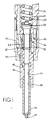
- the injection nozzle comprises a stepped nozzle body 10 which is secured to a tubular elongated nozzle holder 11. Intermediate the holder and the nozzle body is a distance piece 12 and the aforesaid components are held in assembled relationship by means of a cap nut 13.
- the nozzle body defines a blind bore 14 at the blind end of which there is formed a seating 15 which leads into a sac volume from which extends an outlet orifice 16.
- a seating 15 which leads into a sac volume from which extends an outlet orifice 16.
- annular chamber 17 which is connected to a fuel inlet passage 18 extending through the distance piece and the holder to a fuel inlet (not shown) which in the use of the nozzle, is connected by a pipeline to the outlet of a fuel injection pump.
- valve member 19 Within the bore 14 there is located a valve member 19, the portion of the valve member lying between the chamber 17 and the seating being of reduced diameter so as to define with the wall of the bore, an annular clearance.
- the portion of the valve member between the chamber 17 and the open end of the bore is a sliding fit with the wall of the bore.
- the inner end of the valve member is shaped for co-operation with the seating and the opposite end of the valve member extends from the bore the latter adjacent the distance piece 12, being enlarged to accommodate a flange 20 formed on the valve member.
- the holder 11 defines a cylindrical chamber 21 in which is located a coiled compression sprng 22.
- the end of the spring remote from the distance piece is engaged with a suitable spring abutment which may be adjustably mounted in the holder.
- the end of the spring 22 closer to the distance piece is engaged with a spring abutment 23 which is in engagement with the end of the valve member 19 remote from the seating.
- the distance piece 12 defines a bore 24 in which is slidably mounted a piston member in the form of a sleeve 25.
- the sleeve 25 is of stepped form with the narrower end located adjacent the nozzle body.
- the bore 24 is also stepped but the step in the bore is relieved so as to define an annular chamber 26 surrounding the sleeve, the chamber 26 communicating by way of a drilling 27 with the portion of the passage 18 lying within the distance piece.
- the diameter of the narrower end of the sleeve is slightly greater than the diameter of the enlarged portion of the bore 14 in the nozzle body so that a step is defined which acts to limit the downward movement of the sleeve.
- a clearance indicated by the reference letter A exists between the flange 20 on the valve member and the adjacent end of the nozzle body.
- the reference letter B indicates the amount by which the spring abutment 23 projects beyond the end of the holder in the closed position of the valve member.
- a small clearance indicated by the reference letter C exists between the wider end of the sleeve and the spring abutment. The end portion of the spring abutment 23 which engages the valve member, overhangs the valve member so that it can be engaged by the sleeve 25 as will be described.
- the bore in the sleeve is larger in diameter than the valve so that a clearance exists between the valve member and the sleeve, the clearance communicating with the enlarged portion of the bore 14 which accommodates the flange 20 and also by way of a drilling 28 in the abutment 23 and a groove in the end face of the valve member or spring abutment, with the chamber 21 which accommodates the spring.
- This chamber in use is connected to a drain. It will be understood that the opposite end surfaces of the sleeve are exposed to the same pressure.
- the extent of movement of the valve member is determined by the clearance B because when the sleeve 25 engages with the holder 11 the force acting on the sleeve due to the fuel pressure is no longer transmitted to the spring abutment.
- This limited movement of the valve member allows by virtue of the throttling effect of the small gap between the valve member and its seating, a restricted flow of fuel to the associated engine.
- the fuel pressure acting on the valve member will eventually produce a force which is sufficient to move the valve member against the action of the spring and the valve member will move to its fully open position in which the flange 20 engages the sleeve 25.
- the maximum movement of the valve member from the closed position to the fully open position is therefore the sum of the clearances A, B and C and the movement of the valve member in the first stage is equal to the clearance B.
- the force developed on the sleeve due to the fuel pressure at the fuel inlet can be easily adjusted by varying the difference in diameters of the wider and narrower portions of the sleeve.
- the wall of the sleeve can have sufficient thickness to enable it to withstand hydraulic and mechanical forces.
- the nozzle body 10 is of two piece construction. It can of course be formed from a single piece of material.
- the distance piece 12 can be formed integrally with the nozzle body.
Landscapes
- Engineering & Computer Science (AREA)
- Chemical & Material Sciences (AREA)
- Combustion & Propulsion (AREA)
- Mechanical Engineering (AREA)
- General Engineering & Computer Science (AREA)
- Fuel-Injection Apparatus (AREA)
Applications Claiming Priority (2)
| Application Number | Priority Date | Filing Date | Title |
|---|---|---|---|
| GB8825136 | 1988-10-27 | ||
| GB888825136A GB8825136D0 (en) | 1988-10-27 | 1988-10-27 | Fuel injection nozzle |
Publications (1)
| Publication Number | Publication Date |
|---|---|
| EP0366351A2 true EP0366351A2 (de) | 1990-05-02 |
Family
ID=10645866
Family Applications (1)
| Application Number | Title | Priority Date | Filing Date |
|---|---|---|---|
| EP19890310738 Withdrawn EP0366351A2 (de) | 1988-10-27 | 1989-10-18 | Kraftstoffeinspritzdüse |
Country Status (3)
| Country | Link |
|---|---|
| EP (1) | EP0366351A2 (de) |
| JP (1) | JPH02169863A (de) |
| GB (1) | GB8825136D0 (de) |
Cited By (1)
| Publication number | Priority date | Publication date | Assignee | Title |
|---|---|---|---|---|
| GB2256304A (en) * | 1991-05-27 | 1992-12-02 | Sony Magnescale Inc | Magnetic tape transfer apparatus |
-
1988
- 1988-10-27 GB GB888825136A patent/GB8825136D0/en active Pending
-
1989
- 1989-10-18 EP EP19890310738 patent/EP0366351A2/de not_active Withdrawn
- 1989-10-26 JP JP27963389A patent/JPH02169863A/ja active Pending
Cited By (1)
| Publication number | Priority date | Publication date | Assignee | Title |
|---|---|---|---|---|
| GB2256304A (en) * | 1991-05-27 | 1992-12-02 | Sony Magnescale Inc | Magnetic tape transfer apparatus |
Also Published As
| Publication number | Publication date |
|---|---|
| GB8825136D0 (en) | 1988-11-30 |
| JPH02169863A (ja) | 1990-06-29 |
Similar Documents
| Publication | Publication Date | Title |
|---|---|---|
| US4909444A (en) | Poppet covered orifice fuel injection nozzle | |
| US4889288A (en) | Fuel injection nozzle | |
| US4537359A (en) | Fuel injection nozzles | |
| US4591100A (en) | Injection nozzle | |
| US5575253A (en) | Fuel pumping apparatus | |
| GB2232203A (en) | C.i. engine fuel injector | |
| EP0366351A2 (de) | Kraftstoffeinspritzdüse | |
| EP0697518B1 (de) | Kraftstoffeinspritzdüse | |
| US4848668A (en) | Fuel injection nozzles | |
| US4836454A (en) | Fuel injection nozzles | |
| US4981267A (en) | Fuel injection nozzle | |
| KR20010080312A (ko) | 연료 분사 밸브 | |
| US4941613A (en) | Fuel injection nozzle | |
| US4513916A (en) | Fuel injection nozzle | |
| US4917306A (en) | Fuel injection nozzle | |
| GB2204357A (en) | I. C. engine fuel injection nozzle | |
| US4872614A (en) | Fuel injection nozzle | |
| CA1145218A (en) | Fuel injection nozzle | |
| WO1992019857A1 (en) | Fuel injection nozzle | |
| GB2215397A (en) | I.C. engine fuel injection nozzle | |
| US20030116640A1 (en) | Reduced-leakage pressure supply for fuel injectors | |
| EP0572134A1 (de) | Kraftstoffeinspritzdüse | |
| GB2232202A (en) | C.i. engine fuel injector | |
| GB2215396A (en) | I.C. engine fuel injection nozzle | |
| EP0375130A2 (de) | Kraftstoffeinspritzdüse |
Legal Events
| Date | Code | Title | Description |
|---|---|---|---|
| PUAI | Public reference made under article 153(3) epc to a published international application that has entered the european phase |
Free format text: ORIGINAL CODE: 0009012 |
|
| AK | Designated contracting states |
Kind code of ref document: A2 Designated state(s): DE ES FR GB IT |
|
| STAA | Information on the status of an ep patent application or granted ep patent |
Free format text: STATUS: THE APPLICATION HAS BEEN WITHDRAWN |
|
| 18W | Application withdrawn |
Withdrawal date: 19901110 |
|
| R18W | Application withdrawn (corrected) |
Effective date: 19901110 |