EP0366278B1 - Hydraulic pressure control valve - Google Patents
Hydraulic pressure control valve Download PDFInfo
- Publication number
- EP0366278B1 EP0366278B1 EP89309994A EP89309994A EP0366278B1 EP 0366278 B1 EP0366278 B1 EP 0366278B1 EP 89309994 A EP89309994 A EP 89309994A EP 89309994 A EP89309994 A EP 89309994A EP 0366278 B1 EP0366278 B1 EP 0366278B1
- Authority
- EP
- European Patent Office
- Prior art keywords
- hydraulic pressure
- pressure control
- control valve
- bore
- valve body
- Prior art date
- Legal status (The legal status is an assumption and is not a legal conclusion. Google has not performed a legal analysis and makes no representation as to the accuracy of the status listed.)
- Expired - Lifetime
Links
- 239000000463 material Substances 0.000 claims description 5
- 239000002184 metal Substances 0.000 claims description 2
- 230000002093 peripheral effect Effects 0.000 description 4
- 229910000975 Carbon steel Inorganic materials 0.000 description 2
- 239000010962 carbon steel Substances 0.000 description 2
- 238000007796 conventional method Methods 0.000 description 2
- 238000000034 method Methods 0.000 description 2
- 230000001105 regulatory effect Effects 0.000 description 2
- 208000019901 Anxiety disease Diseases 0.000 description 1
- 230000002159 abnormal effect Effects 0.000 description 1
- 230000036506 anxiety Effects 0.000 description 1
- 238000004891 communication Methods 0.000 description 1
- 239000012530 fluid Substances 0.000 description 1
- -1 for example Substances 0.000 description 1
- 230000007257 malfunction Effects 0.000 description 1
- 238000012986 modification Methods 0.000 description 1
- 230000004048 modification Effects 0.000 description 1
- 230000036316 preload Effects 0.000 description 1
- 230000002265 prevention Effects 0.000 description 1
- 238000007789 sealing Methods 0.000 description 1
Images


Classifications
-
- F—MECHANICAL ENGINEERING; LIGHTING; HEATING; WEAPONS; BLASTING
- F16—ENGINEERING ELEMENTS AND UNITS; GENERAL MEASURES FOR PRODUCING AND MAINTAINING EFFECTIVE FUNCTIONING OF MACHINES OR INSTALLATIONS; THERMAL INSULATION IN GENERAL
- F16B—DEVICES FOR FASTENING OR SECURING CONSTRUCTIONAL ELEMENTS OR MACHINE PARTS TOGETHER, e.g. NAILS, BOLTS, CIRCLIPS, CLAMPS, CLIPS OR WEDGES; JOINTS OR JOINTING
- F16B21/00—Means for preventing relative axial movement of a pin, spigot, shaft or the like and a member surrounding it; Stud-and-socket releasable fastenings
- F16B21/10—Means for preventing relative axial movement of a pin, spigot, shaft or the like and a member surrounding it; Stud-and-socket releasable fastenings by separate parts
- F16B21/20—Means for preventing relative axial movement of a pin, spigot, shaft or the like and a member surrounding it; Stud-and-socket releasable fastenings by separate parts for bolts or shafts without holes, grooves, or notches for locking members
-
- B—PERFORMING OPERATIONS; TRANSPORTING
- B60—VEHICLES IN GENERAL
- B60T—VEHICLE BRAKE CONTROL SYSTEMS OR PARTS THEREOF; BRAKE CONTROL SYSTEMS OR PARTS THEREOF, IN GENERAL; ARRANGEMENT OF BRAKING ELEMENTS ON VEHICLES IN GENERAL; PORTABLE DEVICES FOR PREVENTING UNWANTED MOVEMENT OF VEHICLES; VEHICLE MODIFICATIONS TO FACILITATE COOLING OF BRAKES
- B60T11/00—Transmitting braking action from initiating means to ultimate brake actuator without power assistance or drive or where such assistance or drive is irrelevant
- B60T11/10—Transmitting braking action from initiating means to ultimate brake actuator without power assistance or drive or where such assistance or drive is irrelevant transmitting by fluid means, e.g. hydraulic
- B60T11/28—Valves specially adapted therefor
- B60T11/34—Pressure reducing or limiting valves
-
- B—PERFORMING OPERATIONS; TRANSPORTING
- B60—VEHICLES IN GENERAL
- B60T—VEHICLE BRAKE CONTROL SYSTEMS OR PARTS THEREOF; BRAKE CONTROL SYSTEMS OR PARTS THEREOF, IN GENERAL; ARRANGEMENT OF BRAKING ELEMENTS ON VEHICLES IN GENERAL; PORTABLE DEVICES FOR PREVENTING UNWANTED MOVEMENT OF VEHICLES; VEHICLE MODIFICATIONS TO FACILITATE COOLING OF BRAKES
- B60T8/00—Arrangements for adjusting wheel-braking force to meet varying vehicular or ground-surface conditions, e.g. limiting or varying distribution of braking force
- B60T8/26—Arrangements for adjusting wheel-braking force to meet varying vehicular or ground-surface conditions, e.g. limiting or varying distribution of braking force characterised by producing differential braking between front and rear wheels
Definitions
- the present invention relates to a hydraulic control valve for a brake system of an automotive vehicle or the like.
- annular member or element is fixedly mounted to an opening of a component body, or another component to be incorporated in the component body has an end which is fixedly mounted to an inner periphery of the opening.
- the annular element at the opening serves as a spring retainer, a stopper or the like for preventing another component to be inserted in the component body from coming out of the latter, for example.
- 0 157 158 A2 or GB Patent Application No 2 195 408A disclose a hydraulic pressure control valve in which an annular groove is formed in an inner periphery of an opening in a valve body to be threadedly engaged with a portion of a brake master cylinder, which faces toward a hydraulic chamber of the brake master cylinder, and an end of a valve spring is fitted in the groove and is supported at the opening.
- the hydraulic pressure control valve disclosed in the aforesaid EP Patent Publication No. 0 157 158 A2 or GB Patent Application No. 2 195 408A will be considered with reference to the unsteadiness of the support of the annular element.
- the hydraulic pressure control valve is arranged at a portion of a tandem master cylinder, which communicates with a wheel cylinder for rear wheels.
- a way is taken in which a control function of the control valve is released.
- a follower piston of the tandem master cylinder moves excessively or violently to incline a poppet valve element of the hydraulic pressure control valve, thereby releasing the pressure regulating function.
- a hydraulic pressure control valve for use with a master cylinder and a wheel cylinder comprising a valve body formed therein with a stepped bore; a piston inserted in said stepped bore for sliding movement therealong; an inlet chamber defined in said valve body on the side of one end of said piston and capable of communicating with said master cylinder; an outlet chamber defined in said valve body on the side of the other end of said piston and capable of communicating with said wheel cylinder; passage means formed in said piston, said inlet and outlet chambers communicating with each other through said passage means; a valve element arranged in facing relation to an end of said passage means which is located in facing relation to said inlet chamber; and valve spring means for biasing said valve element toward a predetermined position located at the end of said passage means, characterised in that said valve body includes, adjacent said inlet chamber, an opening, a first bore located at said opening and having a diameter of D1, a second bore located on the opposite side of said first bore from said opening and having a diameter of D2, where D1 is larger
- a hydraulic pressure control valve generally designated by the reference numeral 10.
- the valve 10 comprises a valve body 12 which is made of metal and which has a flange 12a intermediate its ends.
- valve body 12 One end of the valve body 12 is provided with male threads 12b for mounting to a discharge section of a master cylinder 81.
- the other end of the valve body 12 is formed with a pipe-mounting section or an outlet chamber 12c for connection to a wheel cylinder 82 of a brake device.
- An O-ring seal 14 located adjacent the right-hand end face of the flange 12a and about the outer periphery of the valve body 12 serves to maintain sealing between the master cylinder 81 and the valve body 12.
- the valve body 12 has a longitudinal bore 18.
- the end of the valve body 12 to be adjacent the master cylinder 81 includes an inlet chamber 32.
- the bore 18 extends to the other end of the valve body 12, where the outlet chamber 12c is located.
- the bore 18 is stepped, and a stepped piston 20 is inserted in the bore 18 for sliding movement therealong.
- the piston 20 has a smaller diameter portion 21 at its right end, as viewed, and, adjacent its other end, a larger diameter portion 22.
- the piston 20 further has a flange 23 between the smaller diameter and larger diameter portions 21 and 22.
- the piston 20 is provided with a through bore or a passage 24.
- the passage 24 is a communication passage connecting the inlet chamber 32 and the outlet chamber 12c.
- a pair of O-ring seals 26a and 26b at the respective larger diameter and smaller diameter portions 22 and 21 prescribe or regulate pressure receiving areas at the respective opposite ends of the piston 20.
- the passage 24 extending centrally through the piston 20 has an opening at which a valve seat 30 is arranged.
- the valve seat 30 faces toward the inlet chamber 32 at the opening of the valve body 12 on the side of the one end thereof.
- a poppet valve element 40 made of plastic is accommodated in the inlet chamber 32.
- the poppet valve element 40 is a molded article made of plastic, and has a domed valve section 41 at a left-hand or lower end center and an annular rim 42 surrounding the valve section 41.
- the rim 42 and the domed section 41 are joined by a trunk section 43.
- a stem 44 has a smaller diameter than and is arranged adjacent the trunk section 43. The stem 44 considerably projects outwardly from the opening of the valve body 12.
- the stem 44 of the poppet valve element 40 engages a flange or the like of a piston within the master cylinder 81 when the piston within the master cylinder 81 moves violently due to some malfunction, to release the hydraulic pressure control action of the hydraulic pressure control valve 10.
- the poppet valve element 40 is urged against the valve seat 30 under biasing force of a valve spring 46.
- the valve body 12 is of one-piece structure without being divided into two, and a component body 50 is fixedly mounted to the valve body 12 in such a manner that the component body 50 is fitted in the inlet chamber 32 and an end face of the component body 50 is caulked to the one end of the valve body 12.
- the valve spring 46 has one end thereof which is supported by the poppet valve element 40.
- the other end of the valve spring 46 is supported by an annular or circular element 60' which is located at an opening 54 of the component body 50.
- the component body 50 is made of free cutting carbon steel (JIS: SUM 24L), while the annular element 60 is made of cold rolled carbon steel (JIS: SPCC).
- the dish-shaped plate 60 may be made of material identical with that of the component body 50.
- the component body 50 includes, in addition to the opening 54, a first bore 51 located at the opening 54 and having a diameter D1, and a second bore 52 located on the opposite side of the first bore 51 from the opening 54 and having a diameter D2, where D1 is larger than D2.
- the component body 50 is annular in shape and is provided at its one end with the opening 54.
- the opening 54 and the first and second bores 51 and 52 are in concentric relation to an outer periphery of the component body 50.
- the opening 54, the first bore 51 and the second bore 52 are located in coaxial relation to each other.
- a step 53 is formed through which the first and second bores 51 and 52 are connected to each other.
- the step 53 extends substantially perpendicularly to an axis of the component body 50.
- annular or circular dish-shaped plate 60 having its outer peripheral dimension or outer diameter D3 equal to or slightly less than the diameter D1 at freedom is inserted into the first bore 51 in the component body 50. Subsequently, as shown in Fig. 2(B), the annular dish-shaped plate 60 is urged against the step 53 of the component body 50 by a tubular press tool 70 until the dish-shaped plate 60 is deformed into a planar-plate configuration. As illustrated in Fig.
- the diameter D3' of the annular element 60' increases to a value larger than the diameter D1 of the first bore 51, so that the outer peripheral portion of the annular element 60' is partially bitten to the inner wall of the first bore 51.
- the annular element 60' serving as a spring retainer for the end of the valve spring 46, which is remote from the one end of the piston 20, is firmly mounted fixedly to the component body 50.
- the dish-shaped plate 60 may be provided at its periphery with a plurality of cut-outs 183, as shown in Fig. 3.
- the height h of each cut-out 183 or each projection may be such that, when the dish-shaped plate 60 is deformed into the annular element 60' after force-fitting, all of the projections are bitten to the periphery of the first bore 51.
- the projections may be semi-circular in shape.
- the head section 44 of the poppet valve element 40 which is remote from the end of the passage 24, projects considerably outwardly from the opening of the valve body 12, in order to release the pressure regulating action of the control valve 10 at fail. However, it is dispensed with to project the head section 44 if such fail countermeasure is not required.
- FIG. 4 fragmentarily illustrates a hydraulic pressure control valve according to another embodiment of the invention.
- components and parts like or similar to those shown in Fig. 1 are designated by the same or like reference numerals, and the description of such like or similar components and parts will be omitted to avoid repetition.
- a component body 50 is composed of a poppet casing portion 500 and a ring portion 501 serving as a spring retainer.
- the poppet casing portion 500 has first and second bores 51 and 52 which are connected to each other through a step bore 53.
- the third bore 502 formed in the poppet casing portion 500 has a slightly larger diameter than the diameter of an end of the piston 20, which is received in the third bore 502.
- the first through third bores 51, 52 and 502 are arranged in coaxial relation to each other and in concentric relation to the outer periphery of the component body 50.
- the component body 50 has an inner perripheral groove defined by the outer periphery of the smaller diameter portion 21 of the stepped piston 20, the ring portion 501 and an end of the poppet casing portion 500 remote from the opening 54.
- the o-ring seal 26b is received in the inner peripheral groove of the component body 50.
- An o-ring seal 26c is additionally provided in concentric relation to the O-ring seal 26b which is arranged about the outer periphery of the smaller-diameter end 21 of the stepped piston 20.
- the O-ring seal 26c seals between the periphery of the stepped bore 18 in the valve body 12 and the outer peripheral surface of the poppet casing portion 500.
- the poppet casing portion 500 has, at its outer periphery, a step 503 to which the end of the valve body 12 adjacent the opening 54 is caulked.
- the embodiment shown in Fig. 4 is effective in prevention of the O-ring seal 26b around the smaller-diameter portion 21 of the stepped piston 20, from coming out of an annular groove defined by the second bore 52 and the smaller-diameter portion 21. That is, in the embodiment illustrated in Fig. 1, it may be possible for the O-ring seal 26b to move toward the inlet chamber 32, and for the leg 42 of the poppet valve element 40 to get into the groove defined by the second bore 52 and the smaller-diameter portion 21. The embodiment shown in Fig. 4 can effectively prevent this occurring.
- the invention is applicable to a wide area as a technique in which an annular element is fixedly mounted to an inner periphery of an opening.
Landscapes
- Engineering & Computer Science (AREA)
- Mechanical Engineering (AREA)
- Transportation (AREA)
- General Engineering & Computer Science (AREA)
- Hydraulic Control Valves For Brake Systems (AREA)
- Control Of Transmission Device (AREA)
- Gear-Shifting Mechanisms (AREA)
Description
- The present invention relates to a hydraulic control valve for a brake system of an automotive vehicle or the like.
- Generally there are many structures in which an annular member or element is fixedly mounted to an opening of a component body, or another component to be incorporated in the component body has an end which is fixedly mounted to an inner periphery of the opening. The annular element at the opening serves as a spring retainer, a stopper or the like for preventing another component to be inserted in the component body from coming out of the latter, for example.
- Conventionally, as a technique in which an annular element or another internal component is fixedly mounted to the opening of the component body, a way is well known in which an annular groove is formed in the inner periphery of the opening, and the annular element such as a C-shaped ring or the like or an end of another internal component is fitted in the annular groove. For instance, EP Patent Publication no. 0 157 158 A2 or GB Patent Application No 2 195 408A disclose a hydraulic pressure control valve in which an annular groove is formed in an inner periphery of an opening in a valve body to be threadedly engaged with a portion of a brake master cylinder, which faces toward a hydraulic chamber of the brake master cylinder, and an end of a valve spring is fitted in the groove and is supported at the opening.
- With the conventional technique described above, first, considerable time is taken since another groove must be processed at the inner periphery of the opening and, moreover an annular element or another internal component must be fitted in the groove. Secondly, because the annular element or another internal component is fitted merely in the groove, the support of the annular element or another compartment is unsteady.
- For instance, the hydraulic pressure control valve disclosed in the aforesaid EP Patent Publication No. 0 157 158 A2 or GB Patent Application No. 2 195 408A will be considered with reference to the unsteadiness of the support of the annular element. Generally, the hydraulic pressure control valve is arranged at a portion of a tandem master cylinder, which communicates with a wheel cylinder for rear wheels. When failure occurs in a brake circuit for front wheels, a way is taken in which a control function of the control valve is released. At failure, a follower piston of the tandem master cylinder moves excessively or violently to incline a poppet valve element of the hydraulic pressure control valve, thereby releasing the pressure regulating function. Accordingly, since a biased or one-sided force is applied to a valve spring which urges the posset valve element, it is important to ensure the support of the valve spring. In this respect, it is impossible for the conventional technique to sufficiently respond to the necessity that is the stability or steadiness of the support of the valve spring.
- In accordance with the present invention a hydraulic pressure control valve for use with a master cylinder and a wheel cylinder comprising a valve body formed therein with a stepped bore; a piston inserted in said stepped bore for sliding movement therealong; an inlet chamber defined in said valve body on the side of one end of said piston and capable of communicating with said master cylinder; an outlet chamber defined in said valve body on the side of the other end of said piston and capable of communicating with said wheel cylinder; passage means formed in said piston, said inlet and outlet chambers communicating with each other through said passage means; a valve element arranged in facing relation to an end of said passage means which is located in facing relation to said inlet chamber; and valve spring means for biasing said valve element toward a predetermined position located at the end of said passage means, characterised in that said valve body includes, adjacent said inlet chamber, an opening, a first bore located at said opening and having a diameter of D₁, a second bore located on the opposite side of said first bore from said opening and having a diameter of D₂, where D₁ is larger than D₂, and a step through which said first and second bores are connected to each other; and that an annular element is fixedly mounted to said valve body in such a manner that an annular dish-shaped plate forming said annular element is urged against said step of said valve body until said dish-shaped plate is deformed into a planar-plate configuration, to bite an outer periphery of said dish-shaped plate to a periphery of said first bore, said annular element serving as a spring retainer for supporting an end of said valve spring means which is remote from the one end of said piston, the diameter of the central hole of said annular element being less than that of said second bore.
- The invention will now be described further by way of example with reference to the accompanying drawings in which :-
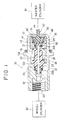
- Fig 1 is a longitudinal cross-sectional view of a hydraulic pressure control valve according to an embodiment of the invention;
- Figs 2(A) through 2(C) are fragmentary views showing a support structure for an annular element;
- Fig 3 is a front elevational view of a modification of a dish-shaped plate forming the annular element; and
- Fig 4 is a fragmentary view of another embodiment of the invention.
- Referring to Fig 1, there is shown a hydraulic pressure control valve, generally designated by the
reference numeral 10. - The
valve 10 comprises avalve body 12 which is made of metal and which has aflange 12a intermediate its ends. - One end of the
valve body 12 is provided withmale threads 12b for mounting to a discharge section of amaster cylinder 81. The other end of thevalve body 12 is formed with a pipe-mounting section or anoutlet chamber 12c for connection to awheel cylinder 82 of a brake device. An O-ring seal 14 located adjacent the right-hand end face of theflange 12a and about the outer periphery of thevalve body 12 serves to maintain sealing between themaster cylinder 81 and thevalve body 12. - The
valve body 12 has alongitudinal bore 18. The end of thevalve body 12 to be adjacent themaster cylinder 81 includes aninlet chamber 32. Thebore 18 extends to the other end of thevalve body 12, where theoutlet chamber 12c is located. Thebore 18 is stepped, and astepped piston 20 is inserted in thebore 18 for sliding movement therealong. Thepiston 20 has asmaller diameter portion 21 at its right end, as viewed, and, adjacent its other end, alarger diameter portion 22. Thepiston 20 further has aflange 23 between the smaller diameter andlarger diameter portions - The
piston 20 is provided with a through bore or apassage 24. Thepassage 24 is a communication passage connecting theinlet chamber 32 and theoutlet chamber 12c. A pair of O-ring seals smaller diameter portions piston 20. At the stage in which hydraulic pressure discharged from themaster cylinder 81 is low, thepiston 20 is loaded byspring 28, and theflange 23 of thepiston 20 abuts against astep 12d of thevalve body 12, so that thepiston 20 is held stationary. - The
passage 24 extending centrally through thepiston 20 has an opening at which avalve seat 30 is arranged. Thevalve seat 30 faces toward theinlet chamber 32 at the opening of thevalve body 12 on the side of the one end thereof. Apoppet valve element 40 made of plastic is accommodated in theinlet chamber 32. When the hydraulic pressure reaches a predetermined value, the force acting upon the difference between the larger-diameter and smaller-diameter portions preload spring 28, so that thepiston 20 moves toward theinlet chamber 32. By this movement, thepoppet valve element 40 is seated on thevalve seat 30. Thus, the known hydraulic control is effected. Thepiston 20 is made of material such as, for example, plastic which has a certain elasticity or resiliency. Accordingly, when thepiston 20 moves violently so as to be abutted against themetallic valve body 12, no abnormal or foreign sound occurs to cause anxiety. Thus, it is no longer necessary to form a restriction which reduces the area of thepassage 24 for hydraulic fluid, in order to prevent thepiston 20 from being returned violently. - The
poppet valve element 40 is a molded article made of plastic, and has adomed valve section 41 at a left-hand or lower end center and anannular rim 42 surrounding thevalve section 41. Therim 42 and thedomed section 41 are joined by atrunk section 43. Astem 44 has a smaller diameter than and is arranged adjacent thetrunk section 43. Thestem 44 considerably projects outwardly from the opening of thevalve body 12. Thestem 44 of thepoppet valve element 40 engages a flange or the like of a piston within themaster cylinder 81 when the piston within themaster cylinder 81 moves violently due to some malfunction, to release the hydraulic pressure control action of the hydraulicpressure control valve 10. - The
poppet valve element 40 is urged against thevalve seat 30 under biasing force of avalve spring 46. Thevalve body 12 is of one-piece structure without being divided into two, and acomponent body 50 is fixedly mounted to thevalve body 12 in such a manner that thecomponent body 50 is fitted in theinlet chamber 32 and an end face of thecomponent body 50 is caulked to the one end of thevalve body 12. Thevalve spring 46 has one end thereof which is supported by thepoppet valve element 40. The other end of thevalve spring 46 is supported by an annular or circular element 60' which is located at an opening 54 of thecomponent body 50. Thecomponent body 50 is made of free cutting carbon steel (JIS: SUM 24L), while theannular element 60 is made of cold rolled carbon steel (JIS: SPCC). However, the dish-shaped plate 60 may be made of material identical with that of thecomponent body 50. - A structure for mounting or supporting the annular element 60' can be seen in Figs. 2(A) through 2(C). The
component body 50 includes, in addition to theopening 54, afirst bore 51 located at theopening 54 and having a diameter D₁, and asecond bore 52 located on the opposite side of thefirst bore 51 from theopening 54 and having a diameter D₂, where D₁ is larger than D₂. Thecomponent body 50 is annular in shape and is provided at its one end with the opening 54. The opening 54 and the first andsecond bores component body 50. The opening 54, thefirst bore 51 and thesecond bore 52 are located in coaxial relation to each other. Astep 53 is formed through which the first andsecond bores step 53 extends substantially perpendicularly to an axis of thecomponent body 50. - As illustrated in Fig. 2(A), an annular or circular dish-
shaped plate 60 having its outer peripheral dimension or outer diameter D₃ equal to or slightly less than the diameter D₁ at freedom is inserted into thefirst bore 51 in thecomponent body 50. Subsequently, as shown in Fig. 2(B), the annular dish-shaped plate 60 is urged against thestep 53 of thecomponent body 50 by atubular press tool 70 until the dish-shaped plate 60 is deformed into a planar-plate configuration. As illustrated in Fig. 2(C), when the dish-shaped plate 60 is deformed into the planar and annular element 60', the diameter D₃' of the annular element 60' increases to a value larger than the diameter D₁ of thefirst bore 51, so that the outer peripheral portion of the annular element 60' is partially bitten to the inner wall of thefirst bore 51. Thus, the annular element 60' serving as a spring retainer for the end of thevalve spring 46, which is remote from the one end of thepiston 20, is firmly mounted fixedly to thecomponent body 50. - In connection with the above, the dish-shaped
plate 60 may be provided at its periphery with a plurality of cut-outs 183, as shown in Fig. 3. In this case, the height h of each cut-out 183 or each projection may be such that, when the dish-shapedplate 60 is deformed into the annular element 60' after force-fitting, all of the projections are bitten to the periphery of thefirst bore 51. In this connection, the projections may be semi-circular in shape. - In the illustrated embodiment, the
head section 44 of thepoppet valve element 40, which is remote from the end of thepassage 24, projects considerably outwardly from the opening of thevalve body 12, in order to release the pressure regulating action of thecontrol valve 10 at fail. However, it is dispensed with to project thehead section 44 if such fail countermeasure is not required. - Fig. 4 fragmentarily illustrates a hydraulic pressure control valve according to another embodiment of the invention. In Fig. 4, components and parts like or similar to those shown in Fig. 1 are designated by the same or like reference numerals, and the description of such like or similar components and parts will be omitted to avoid repetition.
- In the embodiment illustrated in Fig. 4, a
component body 50 is composed of apoppet casing portion 500 and aring portion 501 serving as a spring retainer. Thepoppet casing portion 500 has first andsecond bores third bore 502 formed in thepoppet casing portion 500 has a slightly larger diameter than the diameter of an end of thepiston 20, which is received in thethird bore 502. The first throughthird bores component body 50. Thecomponent body 50 has an inner perripheral groove defined by the outer periphery of thesmaller diameter portion 21 of the steppedpiston 20, thering portion 501 and an end of thepoppet casing portion 500 remote from the opening 54.The o-ring seal 26b is received in the inner peripheral groove of thecomponent body 50. An o-ring seal 26c is additionally provided in concentric relation to the O-ring seal 26b which is arranged about the outer periphery of the smaller-diameter end 21 of the steppedpiston 20. The O-ring seal 26c seals between the periphery of the stepped bore 18 in thevalve body 12 and the outer peripheral surface of thepoppet casing portion 500. Thepoppet casing portion 500 has, at its outer periphery, astep 503 to which the end of thevalve body 12 adjacent theopening 54 is caulked. - The embodiment shown in Fig. 4 is effective in prevention of the O-
ring seal 26b around the smaller-diameter portion 21 of the steppedpiston 20, from coming out of an annular groove defined by thesecond bore 52 and the smaller-diameter portion 21. That is, in the embodiment illustrated in Fig. 1, it may be possible for the O-ring seal 26b to move toward theinlet chamber 32, and for theleg 42 of thepoppet valve element 40 to get into the groove defined by thesecond bore 52 and the smaller-diameter portion 21. The embodiment shown in Fig. 4 can effectively prevent this occurring. - The invention is applicable to a wide area as a technique in which an annular element is fixedly mounted to an inner periphery of an opening.
Claims (13)
- A hydraulic pressure control valve for use with a master cylinder (81) and a wheel cylinder (82), comprising:
a valve body (12) formed therein with a stepped bore (18);
a piston (20) inserted in said stepped bore (18) for sliding movement therealong;
an inlet chamber (32) defined in said valve body (12) on the side of one end of said piston (20) and capable of communicating with said master cylinder (81);
an outlet chamber (12c) defined in said valve body (12) on the side of the other end of said piston (20) and capable of communicating with said wheel cylinder (82);
passage means (24) formed in said piston (20), said inlet and outlet chambers (32, 12c) communicating with each other through said passage means;
a valve element (40) arranged in facing relation to an end of said passage means (24) which is located in facing relation to said inlet chamber (32); and
valve spring means (46) for biasing said valve element (40) toward a predetermined position located at the end of said passage means (24),
characterised in that said valve body (12) includes, adjacent said inlet chamber (32), an opening (54) , a first bore (51) located at said opening and having a diameter of D₁, a second bore (52) located on the opposite side of said first bore from said opening and having a diameter of D₂, where D₁ is larger than D₂, and a step (53) through which said first and second bores are connected to each other; and that an annular element (60') is fixedly mounted to said valve body (12) in such a manner that an annular dish-shaped plate (60) forming said annular element is urged against said step (53) of said valve body until said dish-shaped plate is deformed into a planar-plate configuration, to bite an outer periphery of said dish-shaped plate (60) to a periphery of said first bore (51), said annular element (60') serving as a spring retainer for supporting an end of said valve spring means (46) which is remote from the one end of said piston (20), the diameter of the central hole of said annular element (60') being less than that of said second bore (52). - A hydraulic pressure control valve according to claim 1, characterized in that said valve body (12) is made of metal, and said piston (20) is made of material having an elasticity.
- A hydraulic pressure control valve according to claim 2, characterized in that said valve body (12) is made of plastic material.
- A hydraulic pressure control valve according to claim 1, characterized in that said valve body (12) is of one-piece structure.
- A hydraulic pressure control valve according to claim 1, characterized in that a component body (50) is fixedly mounted to said valve body (12) and is provided therein with said opening (54) and said first and second bores (51, 52).
- A hydraulic pressure control valve according to claim 5, characterized in that said component body (50) is caulked to said valve body (12).
- A hydraulic pressure control valve according to claim 5, characterized in that said component body (50) is annular is shape and is provided at its one end with said opening (54), said opening and said first and second bores (51,52) being in concentric relation to an outer periphery of said component body.
- A hydraulic pressure control valve according to claim 1, characterized in that said step (53) extends substantially perpendicularly to an axis of said valve body (12).
- A hydraulic pressure control valve according to claim 1, characterized in that said opening (54), said first bore (51) and said second bore (52) are located in coaxial relation to each other.
- A hydraulic pressure control valve according to claim 1, characterized in that said dish-shaped plate (60) has its diameter at least equal to said diameter D₁ of said first bore (51).
- A hydraulic pressure control valve according to claim 1, characterized in that said dish-shaped plate (60) is provided at its periphery with a plurality of cut-outs (183).
- A hydraulic pressure control valve according to claim 5, characterized in that said dish-shaped plate (60) is made of material different from that of which said component body (50) is made.
- A hydraulic pressure control valve according to claim 1, characterized in that part of the valve element (40) projects through the central hole of said annular element (60').
Applications Claiming Priority (2)
| Application Number | Priority Date | Filing Date | Title |
|---|---|---|---|
| JP63267898A JP2782207B2 (en) | 1988-10-24 | 1988-10-24 | Machine parts and hydraulic pressure control valves containing the parts |
| JP267898/88 | 1988-10-24 |
Publications (3)
| Publication Number | Publication Date |
|---|---|
| EP0366278A2 EP0366278A2 (en) | 1990-05-02 |
| EP0366278A3 EP0366278A3 (en) | 1991-02-06 |
| EP0366278B1 true EP0366278B1 (en) | 1994-03-16 |
Family
ID=17451154
Family Applications (1)
| Application Number | Title | Priority Date | Filing Date |
|---|---|---|---|
| EP89309994A Expired - Lifetime EP0366278B1 (en) | 1988-10-24 | 1989-09-29 | Hydraulic pressure control valve |
Country Status (4)
| Country | Link |
|---|---|
| US (1) | US5052759A (en) |
| EP (1) | EP0366278B1 (en) |
| JP (1) | JP2782207B2 (en) |
| DE (1) | DE68913901T2 (en) |
Families Citing this family (5)
| Publication number | Priority date | Publication date | Assignee | Title |
|---|---|---|---|---|
| JP3348165B2 (en) * | 1993-04-09 | 2002-11-20 | 株式会社ボッシュオートモーティブシステム | Proportioning valve |
| EP0784552A4 (en) * | 1994-10-24 | 1997-12-17 | Hilite Ind Inc | Staked design for inline proportioning valve |
| JP3140655B2 (en) * | 1995-03-13 | 2001-03-05 | ボッシュ ブレーキ システム株式会社 | Hydraulic pressure control valve |
| DE10106958B4 (en) * | 2000-02-29 | 2022-02-17 | Schaeffler Technologies AG & Co. KG | hydraulic system |
| KR20020061969A (en) * | 2001-01-19 | 2002-07-25 | 주식회사 만도 | Proportioning valve for brake system |
Citations (1)
| Publication number | Priority date | Publication date | Assignee | Title |
|---|---|---|---|---|
| EP0157158A2 (en) * | 1984-04-02 | 1985-10-09 | AlliedSignal Inc. | Master cylinder and proportioning valve therefore |
Family Cites Families (17)
| Publication number | Priority date | Publication date | Assignee | Title |
|---|---|---|---|---|
| US2058452A (en) * | 1934-11-08 | 1936-10-27 | Lycoming Mfg Company | Attachable washer |
| GB566073A (en) * | 1943-05-06 | 1944-12-12 | Automotive Prod Co Ltd | Improved locating means for retaining washers and the like |
| US3007726A (en) * | 1959-12-03 | 1961-11-07 | United Carr Fastener Corp | Fastening devices |
| US3359021A (en) * | 1965-06-03 | 1967-12-19 | Waldes Kohinoor Inc | Self-locking retaining rings |
| US3483888A (en) * | 1967-12-15 | 1969-12-16 | Waldes Kohinoor Inc | Self-locking retaining rings and assemblies employing same |
| JPS5218965B2 (en) * | 1973-07-20 | 1977-05-25 | ||
| JPS5124661A (en) * | 1974-08-24 | 1976-02-28 | Asahi Organic Chem Ind | TSUGITEYOKANAGATA |
| JPS52126U (en) * | 1975-06-19 | 1977-01-05 | ||
| DE3037459A1 (en) * | 1980-10-03 | 1982-05-13 | Alfred Teves Gmbh, 6000 Frankfurt | BRAKE PRESSURE CONTROL VALVE FOR VEHICLE BRAKE SYSTEMS AND METHOD FOR THE PRODUCTION THEREOF |
| DE3236321A1 (en) * | 1982-09-30 | 1984-04-05 | Lucas Industries P.L.C., Birmingham, West Midlands | BRAKE FORCE CONTROLLER FOR A HYDRAULIC VEHICLE BRAKE SYSTEM |
| AU551867B2 (en) * | 1983-09-02 | 1986-05-15 | Nissin Kogyo K.K. | Master cylinder-reducing valve assembly |
| JPS60204708A (en) * | 1984-03-30 | 1985-10-16 | Lion Corp | Humectant |
| US4640554A (en) * | 1984-10-12 | 1987-02-03 | Barr William A | Valve assembly for use in brake pressure control unit |
| US4774809A (en) * | 1985-02-09 | 1988-10-04 | Tokico Ltd. | Tandem type master cylinder with pressure proportioning valve deactivated by a slidable actuating member |
| US4776616A (en) * | 1986-05-26 | 1988-10-11 | Usui Kokusai Sangyo Kabushiki Kaisha | Coupling |
| JPH0343896Y2 (en) * | 1986-09-24 | 1991-09-13 | ||
| US4893878A (en) * | 1988-09-27 | 1990-01-16 | Hilite Industries, Inc. | Inline proportioning valve for brake systems |
-
1988
- 1988-10-24 JP JP63267898A patent/JP2782207B2/en not_active Expired - Lifetime
-
1989
- 1989-09-25 US US07/412,280 patent/US5052759A/en not_active Expired - Fee Related
- 1989-09-29 EP EP89309994A patent/EP0366278B1/en not_active Expired - Lifetime
- 1989-09-29 DE DE68913901T patent/DE68913901T2/en not_active Expired - Fee Related
Patent Citations (1)
| Publication number | Priority date | Publication date | Assignee | Title |
|---|---|---|---|---|
| EP0157158A2 (en) * | 1984-04-02 | 1985-10-09 | AlliedSignal Inc. | Master cylinder and proportioning valve therefore |
Also Published As
| Publication number | Publication date |
|---|---|
| DE68913901D1 (en) | 1994-04-21 |
| EP0366278A2 (en) | 1990-05-02 |
| DE68913901T2 (en) | 1994-10-13 |
| JP2782207B2 (en) | 1998-07-30 |
| JPH02114047A (en) | 1990-04-26 |
| EP0366278A3 (en) | 1991-02-06 |
| US5052759A (en) | 1991-10-01 |
Similar Documents
| Publication | Publication Date | Title |
|---|---|---|
| US5601275A (en) | Solenoid operated valve | |
| US5681097A (en) | Hydraulic control unit for vehicular anti-lock brake and traction control systems | |
| EP0366278B1 (en) | Hydraulic pressure control valve | |
| KR100313614B1 (en) | Piston with central valve for hydraulic brake system | |
| US6846408B2 (en) | Filter assembly for a control valve in a vehicular brake system | |
| JPH0232532Y2 (en) | ||
| US5050383A (en) | Hydraulic pressure control valve | |
| US6334384B1 (en) | Brake booster | |
| US3964795A (en) | Modular proportioner | |
| US6213566B1 (en) | Brake proportioning in-line ball valve | |
| US6360778B1 (en) | Modulator body and fluid accumulator for use in vehicle brake system | |
| US6295915B1 (en) | Brake booster | |
| US4809505A (en) | Master cylinder | |
| EP0573234B1 (en) | Improvements in pneumatically-operated boosters for vehicle braking systems | |
| EP0393274B1 (en) | Hydraulic pressure control valve for use with brake master cylinder | |
| EP0732242B1 (en) | Fluid pressure control valve apparatus | |
| US5018796A (en) | Hydraulic pressure control valve | |
| EP0457513B1 (en) | Fluid pressure control of braking system | |
| JP3445541B2 (en) | Center valve type master cylinder | |
| US4444437A (en) | Deceleration-sensing modulator valve assembly for vehicle braking systems | |
| JPH106950A (en) | Hydraulic pressure control valve | |
| JPH0218143A (en) | Hydraulic proportioning valve | |
| JP3401431B2 (en) | Hydraulic pressure control valve | |
| EP0084719A1 (en) | Brake pressure proportioning valve | |
| JPH0343089Y2 (en) |
Legal Events
| Date | Code | Title | Description |
|---|---|---|---|
| PUAI | Public reference made under article 153(3) epc to a published international application that has entered the european phase |
Free format text: ORIGINAL CODE: 0009012 |
|
| AK | Designated contracting states |
Kind code of ref document: A2 Designated state(s): DE FR GB |
|
| PUAL | Search report despatched |
Free format text: ORIGINAL CODE: 0009013 |
|
| AK | Designated contracting states |
Kind code of ref document: A3 Designated state(s): DE FR GB |
|
| 17P | Request for examination filed |
Effective date: 19910705 |
|
| 17Q | First examination report despatched |
Effective date: 19920219 |
|
| GRAA | (expected) grant |
Free format text: ORIGINAL CODE: 0009210 |
|
| AK | Designated contracting states |
Kind code of ref document: B1 Designated state(s): DE FR GB |
|
| REF | Corresponds to: |
Ref document number: 68913901 Country of ref document: DE Date of ref document: 19940421 |
|
| ET | Fr: translation filed | ||
| PLBE | No opposition filed within time limit |
Free format text: ORIGINAL CODE: 0009261 |
|
| STAA | Information on the status of an ep patent application or granted ep patent |
Free format text: STATUS: NO OPPOSITION FILED WITHIN TIME LIMIT |
|
| 26N | No opposition filed | ||
| PGFP | Annual fee paid to national office [announced via postgrant information from national office to epo] |
Ref country code: FR Payment date: 19980909 Year of fee payment: 10 |
|
| PGFP | Annual fee paid to national office [announced via postgrant information from national office to epo] |
Ref country code: GB Payment date: 19981001 Year of fee payment: 10 |
|
| PGFP | Annual fee paid to national office [announced via postgrant information from national office to epo] |
Ref country code: DE Payment date: 19981005 Year of fee payment: 10 |
|
| PG25 | Lapsed in a contracting state [announced via postgrant information from national office to epo] |
Ref country code: GB Free format text: LAPSE BECAUSE OF NON-PAYMENT OF DUE FEES Effective date: 19990929 |
|
| GBPC | Gb: european patent ceased through non-payment of renewal fee |
Effective date: 19990929 |
|
| PG25 | Lapsed in a contracting state [announced via postgrant information from national office to epo] |
Ref country code: FR Free format text: LAPSE BECAUSE OF NON-PAYMENT OF DUE FEES Effective date: 20000531 |
|
| PG25 | Lapsed in a contracting state [announced via postgrant information from national office to epo] |
Ref country code: DE Free format text: LAPSE BECAUSE OF NON-PAYMENT OF DUE FEES Effective date: 20000701 |
|
| REG | Reference to a national code |
Ref country code: FR Ref legal event code: ST |