EP0366224A2 - True-amplitude dip moveout correction - Google Patents
True-amplitude dip moveout correction Download PDFInfo
- Publication number
- EP0366224A2 EP0366224A2 EP89306237A EP89306237A EP0366224A2 EP 0366224 A2 EP0366224 A2 EP 0366224A2 EP 89306237 A EP89306237 A EP 89306237A EP 89306237 A EP89306237 A EP 89306237A EP 0366224 A2 EP0366224 A2 EP 0366224A2
- Authority
- EP
- European Patent Office
- Prior art keywords
- seismic
- corrected
- moveout
- dip
- synthetic dataset
- Prior art date
- Legal status (The legal status is an assumption and is not a legal conclusion. Google has not performed a legal analysis and makes no representation as to the accuracy of the status listed.)
- Granted
Links
- 238000012937 correction Methods 0.000 title claims abstract description 38
- 238000000034 method Methods 0.000 claims abstract description 70
- 238000007598 dipping method Methods 0.000 claims description 29
- 238000002310 reflectometry Methods 0.000 claims description 20
- 238000013508 migration Methods 0.000 claims description 17
- 230000005012 migration Effects 0.000 claims description 17
- 230000003595 spectral effect Effects 0.000 claims description 6
- 230000003213 activating effect Effects 0.000 claims description 3
- 230000004913 activation Effects 0.000 claims description 3
- 230000036962 time dependent Effects 0.000 claims description 3
- 238000004519 manufacturing process Methods 0.000 claims 1
- 230000008569 process Effects 0.000 abstract description 18
- 238000003384 imaging method Methods 0.000 abstract description 7
- 238000013461 design Methods 0.000 abstract description 2
- 238000012545 processing Methods 0.000 description 7
- 239000013598 vector Substances 0.000 description 6
- 238000010586 diagram Methods 0.000 description 5
- 238000013459 approach Methods 0.000 description 3
- 238000013507 mapping Methods 0.000 description 3
- 230000008901 benefit Effects 0.000 description 2
- 230000014509 gene expression Effects 0.000 description 2
- 238000001228 spectrum Methods 0.000 description 2
- 238000010561 standard procedure Methods 0.000 description 2
- 230000005526 G1 to G0 transition Effects 0.000 description 1
- 238000009933 burial Methods 0.000 description 1
- 230000008859 change Effects 0.000 description 1
- 230000001419 dependent effect Effects 0.000 description 1
- 238000009795 derivation Methods 0.000 description 1
- 230000001066 destructive effect Effects 0.000 description 1
- 230000000694 effects Effects 0.000 description 1
- 238000011156 evaluation Methods 0.000 description 1
- 230000009467 reduction Effects 0.000 description 1
- 238000005070 sampling Methods 0.000 description 1
- 239000007787 solid Substances 0.000 description 1
- 230000002123 temporal effect Effects 0.000 description 1
- 230000009466 transformation Effects 0.000 description 1
- 230000001131 transforming effect Effects 0.000 description 1
Images


Classifications
-
- G—PHYSICS
- G01—MEASURING; TESTING
- G01V—GEOPHYSICS; GRAVITATIONAL MEASUREMENTS; DETECTING MASSES OR OBJECTS; TAGS
- G01V1/00—Seismology; Seismic or acoustic prospecting or detecting
- G01V1/28—Processing seismic data, e.g. for interpretation or for event detection
- G01V1/36—Effecting static or dynamic corrections on records, e.g. correcting spread; Correlating seismic signals; Eliminating effects of unwanted energy
- G01V1/362—Effecting static or dynamic corrections; Stacking
-
- G—PHYSICS
- G01—MEASURING; TESTING
- G01V—GEOPHYSICS; GRAVITATIONAL MEASUREMENTS; DETECTING MASSES OR OBJECTS; TAGS
- G01V1/00—Seismology; Seismic or acoustic prospecting or detecting
- G01V1/28—Processing seismic data, e.g. for interpretation or for event detection
- G01V1/282—Application of seismic models, synthetic seismograms
-
- G—PHYSICS
- G01—MEASURING; TESTING
- G01V—GEOPHYSICS; GRAVITATIONAL MEASUREMENTS; DETECTING MASSES OR OBJECTS; TAGS
- G01V2210/00—Details of seismic processing or analysis
- G01V2210/50—Corrections or adjustments related to wave propagation
- G01V2210/52—Move-out correction
- G01V2210/522—Dip move-out [DMO]
-
- G—PHYSICS
- G01—MEASURING; TESTING
- G01V—GEOPHYSICS; GRAVITATIONAL MEASUREMENTS; DETECTING MASSES OR OBJECTS; TAGS
- G01V2210/00—Details of seismic processing or analysis
- G01V2210/60—Analysis
- G01V2210/61—Analysis by combining or comparing a seismic data set with other data
- G01V2210/614—Synthetically generated data
Definitions
- This invention deals with an improved method and apparatus for three-dimensional seismic imaging by which seismic amplitudes are preserved, so that the amplitudes on the final seismic image are proportional to the reflectivity of the earth, regardless of the geologic dip, depth of burial, or seismic recording geometry.
- the technique is easily specialized to two-dimensional DMO, in the case where the shot-receiver axis lies along the direction of survey.
- CDP Common-depth-point stacking
- NMO normal moveout
- DMO dip moveout
- the present invention provides a practical method and apparatus for transforming a set of areally-distributed seismic field traces into an image whose amplitudes are directly proportional to the earth's reflectivity.
- the invention provides apparatus for carrying out true-amplitude dip moveout on seismic data, which comprises means for selecting a reflectivity and dip for a theoretical dipping layer in three dimensions; means for generating a synthetic dataset corresponding to reflection from the theoretical dipping layer using a known deconvolved source wavelet and a conventional three dimensional scalar wave equation; means for correcting the synthetic dataset for spherical divergence to provide a spherical divergence corrected synthetic dataset; means for correcting the spherical divergence corrected synthetic dataset for normal moveout to provide a normal moveout corrected synthetic dataset; means for correcting the normal moveout corrected synthetic dataset for dip moveout using an extra degree of freedom in the dip moveout equation to provide a corrected synthetic dataset; means for performing zero-offset migration on the corrected synthetic dataset to provide a migrated seismic image; means for comparing the migrated seismic image with a known true-amplitude image derived from the known reflectivity and the known source wavelet from the theoretical dipping layer; means for adjusting the migrated seismic
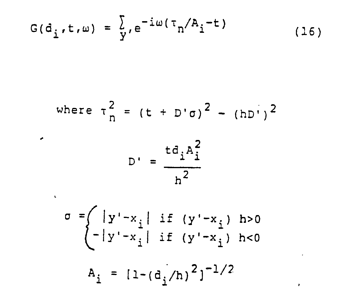
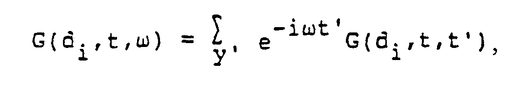
- the invention also provides an apparatus for carrying out true-amplitude dip moveout on seismic traces generated in a survey area by seismic receivers after activation of seismic energy sources, which comprises: means for dividing the survey area into a set of geometrical figures which function as output cells; means for assigning a reference point to each of the output cells; means for calculating a dip moveout aperture as a time dependent function related to a maximum allowable dip; for each output cell, means for identifying the contributing seismic traces which are those seismic traces which meet the conditions that the line connecting the generating receiver and the activating source of that trace intersects the output cell, and that the distance between the midpoint of that line and the reference point of the cell is less than the dip moveout aperture; means for classifying all contributing seismic traces according to their offset; means for computing a DMO correction filter for each offset class by means of the equation: and the Fourier sign convention for Equation (16) is given by and means for inverting the filter and applying the inverted filter to the dip moveout method given by the equation: where S(d i
- the invention further provides an apparatus for producing true-amplitude seismic images which comprises: means for selecting a reflectivity and dip for a theoretical dipping layer in three dimensions; means for generating a synthetic dataset corresponding to reflection from the theoretical dipping layer using a known source wavelet and a conventional three dimensional scalar wave equation; means for correcting the synthetic dataset for spherical divergence to provide a spherical divergence corrected synthetic dataset; means for correcting the spherical divergence corrected synthetic dataset for normal moveout to provide a normal moveout corrected synthetic dataset; means for correcting the normal moveout corrected synthetic dataset for dip moveout using an extra degree of freedom in the dip moveout equation to provide a corrected synthetic dataset; means for performing zero-offset migration on the corrected synthetic dataset to provide a migrated seismic image; means for comparing the migrated seismic image with a known true-amplitude image derived from the known reflectivity and the known source wavelet from the theoretical dipping layer; means for adjusting the migrated seismic image to substantially correspond to the known true-amplitude
- the invention also includes the methods per se .
- An improved DMO process which consists of a calibration method for designing a set of filters that correct the seismic amplitudes so as to preserve true-amplitude imaging.
- These filters can be designed and applied in any known implementation of DMO.
- the filters can be applied in three-dimensional DMO or specialized to two-dimensional DMO. Special particularly convenient forms of the filters result when the spatial sampling of the input traces is reasonably uniform.
- the modified DMO process produces output traces in designated output-cell locations.
- the output traces in all cells may be displayed as a zero-offset three-dimensional unmigrated image of the earth.
- Application of a subsequent 3D zero-offset migration yields traces which may be displayed as a three-dimensional image proportional to the reflectivity of the earth.
- Boldface quantities indicate two-dimensional vectors along the earth's surface.
- P( y ,t h ) deconvolved seismic trace data.
- P s ( y ,t h ) seismic trace data after spherical divergence correction.
- P h ( y , t 0) seismic trace data after NMO correction.
- P0( x i ,t) seismic trace data after DMO correction.
- t 0 NMO-corrected trace time (input time to DMO).
- t zero-offset trace time output time from DMO).
- r trace receiver coordinate s trace source coordinate.
- d i distance between y and x i
- half of the shot-receiver offset ( s - r )/2.
- w(t h ) deconvolved source wavelet.
- y′ a dummy summation variable employed in the definition of the filter G(d i ,t,t′).
- the summation range of y ′ is the same as that of y .
- ⁇ the distance between y ′ and x i .
- D′ the dip that is tangent to the DMO trajectory at distance d i from point x i .
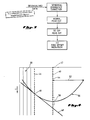
- FIG. 1 a plan view of a 3D seismic survey is shown.
- the seismic energy emanates from source 2 and is received at receiver 4.
- the trace recorded for this source and receiver is conventionally displayed at the source-receiver midpoint position 6, whose Cartesian coordinate vector is denoted by y .
- the energy bounces off the reflector 8 at the reflection point 10, with raypath 12 from source 2 to reflection point 10 and raypath 14 from reflection point 10 to receiver 4.
- the purpose of three-dimensional (3D) DMO is to create an equivalent trace corresponding to the zero-offset raypath 16 and to position that trace at surface location 18, whose Cartesian coordinate is denoted by x i .
- Figure 2 is a section view of raypaths for a dipping reflector displayed in the plane containing the source 22, receiver 24 and reflection point 30.
- the source-receiver offset, the distance between source 22 and receiver 24, has the value 2h.
- Figure 3 shows a processing sequence for producing a true-amplitude image of any reflector, such as the one illustrated in figures 1 and 2.
- the input data has been previously deconvolved to produce a wavelet of approximately constant spectral amplitude over a bandwidth range.
- This step which does not form part the present invention, can be performed by any of a number of standard techniques, with which those skilled in the art are familiar.
- the imaging sequence, shown in Figure 3 is spherical-divergence correction, normal-moveout (NMO) correction, 3D DMO, and 3D zero-offset migration. It is generally understood that the data corresponding to different offsets is stacked together at some stage after the NMO has been performed to improve the signal to noise ratio.
- the spherical-divergence correction in simplest form consists of multiplying each deconvolved trace P( y ,t h ) by t h , to yield P s ( y ,t h ) but the present invention is not limited to this particular form of correction.
- the NMO correction consists of mapping P s ( y ,t h ) to post-NMO time t 0 by the well-known relationship: where v is the rms velocity.
- the migration can be done by any of a number of well-known standard techniques.
- DMO can be equivalently applied to input traces arranged into various sets: common-offset sections, common-shot records, and single-trace sets. For 3D implementations, it is often more convenient to not apply DMO to common-offset sections or common-shot records, but to process each individual input trace in essentially whatever order it appears on the magnetic tape. The improved method of DMO described here can be applied to any of these input-trace organizations.
- Some DMO implementations produce data in which all offsets have been summed together, producing a stack section ready to go immediately into the zero-offset migration algorithm.
- Other DMO implementations produce output traces which are arranged into various sets, to be stacked together after some subsequent processing. In particular, it is useful to keep the DMO outputs separated according to their offsets, so as to allow a velocity analysis after DMO has been applied to the data. After this velocity analysis has been performed, the traces can be corrected for residual NMO errors (occurring in the NMO step that preceded DMO) prior to being stacked and migrated.
- the improved DMO algorithm presented here can be used to produce output traces which are offset-separated or which are already stacked over offset.
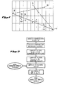
- FIG. 4 shows how the Deregowski and Rocca summation method of DMO is carried out.
- the input seismic trace is shown schematically as the vertical line 40, which is positioned at the source-receiver midpoint position 42, whose Cartesian coordinate is y .
- the individual digitally-recorded amplitudes on the seismic trace are at the discrete time positions indicated by the solid dots, such as 44.
- the DMO process generates a plurality of output traces, such as 46 and 50. This is in keeping with the fact that the DMO process makes no assumption about the angle of dip of the seismic data which governs the location of the zero-offset output trace and therefore must allow each input trace to contribute to a number of output traces within a DMO aperture distance 52. This aperture is generally determined by the maximum physically-allowable dip.
- the Deregowski and Rocca summation method of DMO consists of convolving a time-variant filter with the input trace 40 and then mapping the resultant amplitude along the DMO trajectory 56.
- Derivation of a suitable DMO trajectory is taught by Deregowski and Rocca in the publication referenced above, and is familiar to those skilled in the art.
- the present invention provides an improved time variant filter, which is hereinafter described. For example the set of points 58 is multiplied with the elements of the filter, and the sum of these products is mapped to the time sample 60 on the output trace 46. This process is repeated for every other output trace, such as 50, within the DMO aperture distance 52 on either side of the midpoint 42.
- the elements of the time-variant filter are then applied to a new set of points displaced one time sample deeper than points 58, and the entire process is repeated until all time samples on the input trace 40 have been exhausted. The process is then repeated for the next input trace, and its contributions are summed into the output traces such as 46 and 50. This summation process will lead to constructive and destructive interference. An event with arbitrary dip present in the input data will destructively interfere with itself except at one particular output location 60, which is where the DMO trajectory 56 is tangent to the zero-offset travel time curve 48 for the dipping event.
- the summed results in the output traces are the DMO output product, representative of a zero-offset dataset.
- the current invention provides a method of designing the filters S(d1,t,t′) to ensure that P0( x i t) is a true-amplitude representation of the earth's reflectivity.
- a satisfactory definition of the term "true-amplitude” is required.
- This invention is applicable to several definitions of true-amplitude.
- Figure 5 demonstrates one such definition.
- a flat event 62 and a dipping event 64 are assumed to have the same reflection coefficient.
- the final migrated image of the flat event is the seismic trace 66, while the final migrated image of the dipping event is the seismic trace 68.
- This definition of "true-amplitude” requires that any two isolated events with the same reflection coefficient have the same peak amplitude on the migrated image.
- the peak amplitudes 70 and 72 are shown to be the same in Figure 5. Note, however that the Fourier spectrum 74 of the seismic trace 66 for the flat event shown in Figure 5A has a broader bandwidth than the Fourier spectrum 76 of the seismic trace 68 for the dipping event shown in Figure 58. This is consistent with the shorter wavelet 66 of the flat event in comparison with the dipping event 68. This change in bandwidth is why care must be taken in defining what is meant by "true-amplitude.”
- the bandwidth changes in Figure 5 are an unavoidable result of the obliquity of raypaths, illustrated in Figure 6. Anytime the raypaths deviate from the vertical direction, either due to offset between source 75 and receiver 77 in the case of raypath 78 shown in Figure 6 or due to dip in the case of the zero-offset raypath 80 shown in Figure 6B, the achievable vertical bandwidth, as defined by the wavelets 82 and 84, is lower than the bandwidth on the source wavelets 86 and 88. This unavoidable bandwidth reduction makes it necessary to define "true-amplitude" in some fashion which is independent of the bandwidth of the final wavelet.
- the "constant peak amplitude" definition described above is one possible definition.
- a “constant Fourier spectral amplitude” definition would also be possible.
- the "constant peak amplitude” definition of Figure 5 will be used, although the changes for "constant Fourier spectral amplitude" are readily derivable and amount to multiplying the NMO, DMO and zero-offset migration outputs by the obliquity factors of t o /t h , A i and cos ⁇ , respectively.
- Figure 7 is a plan view of a 3D seismic survey, showing the relationship between the source/receiver geometry of Figure 1 and the output cells in which 3D DMO will create output traces.
- the shot 90 and receiver 92 are connected by a line segment whose center is at the midpoint 94.
- there will generally be other source locations such as 96 and other receiver locations such as 98.
- the area of the survey is to be conceptually divided into a set of geometrical figures such as the rectangle 100. Each such figure is assigned a reference point (usually the centroid of the figure) such as the center of the rectangle 102, whose Cartesian coordinate is x i .
- the DMO aperture for any given output time t is defined by half the segment connecting the two points 104 and 106, which are located vertically above the ends of the DMO trajectory and are symmetrically placed about the midpoint 94.
- the output-driven implementation follows Equation (2) by summing over all input traces y which are within a DMO aperture of fixed output location x i . Once the sum defining the trace at x i is completed, the algorithm moves on to the next output trace at a new location for x i .
- the input-driven method proceeds by taking each input trace and allowing it to contribute to all possible x i within a DMO aperture of it. Once it has contributed to all possible output traces, the next input trace (at a new location y ) is brought in and summed into all its x i locations.
- the modified filters of this invention may, of course, be used in either implementation, but details will be given here only for the output-driven method.
- the key to this invention is a calibration procedure for designing the set of DMO correction filters, S .
- This procedure is shown schematically in Figure 8.
- the procedure begins with a three-dimensional dipping layer such as 8 in figure 1.
- This layer has a known arbitrary dip and a known reflectivity R( ), where is the reflection angle as shown in Figure 2.
- the three-dimensional scalar wave equation is used to generate the synthetic dataset P( y ,t y ) corresponding to a known deconvolved source wavelet w(t h ).
- the calibration procedure then consists of analytically processing P( y ,t h ) through spherical divergence correction, NMO, DMO and zero-offset migration, as shown in Figure 8.
- the DMO is done with an extra degre of freedom, in the form of a set of correction filters S . These filters are then calibrated to ensure that the final migrated output of the processing has an amplitude proportional to the reflectivity R( ⁇ ), regardless of the dip of the event, the depth of the event, or the recording geometry.
- the synthetic data is then processed using a known kinematic form of the 3-D DMO operation, with filters represented by an extra degree of freedom. For example, if the Deregowski and Rocca method is used, the summation in Equation (2) is carried out.
- Equation (2) The expression for the Fourier transformed P o ( x i , ⁇ ) can be written in terms of the summation G: where W ( ⁇ ) is the Fourier transform of the system wavelet w(t h ). It has been found that G( ⁇ ) can be written totally as a function of the midpoint variables y and x i in Equation (2), thus eliminating any explicit dependence on dip.
- Hale's technique employs a set of non-true-amplitude filters S H .
- the procedure for providing a true-amplitude version of Hale's procedure is to replace these filters S H by values which are derived from the true-amplitude filters, S , constructed by the calibration procedure.
- the generic connection between F-K DMO filters and summation DMO filters is a stationary-phase integral evaluation.
- the correct values of S H are where S is the inverse of G given in Equation (16) above.
- these processing steps are carried out using a programmed digital computer.
- Standard programs to carry out the operations involved in each step are well known to those in this field.
Landscapes
- Engineering & Computer Science (AREA)
- Remote Sensing (AREA)
- Physics & Mathematics (AREA)
- Life Sciences & Earth Sciences (AREA)
- Geology (AREA)
- Environmental & Geological Engineering (AREA)
- Acoustics & Sound (AREA)
- General Life Sciences & Earth Sciences (AREA)
- General Physics & Mathematics (AREA)
- Geophysics (AREA)
- Geophysics And Detection Of Objects (AREA)
- Image Processing (AREA)
- Measurement Of Mechanical Vibrations Or Ultrasonic Waves (AREA)
- Testing, Inspecting, Measuring Of Stereoscopic Televisions And Televisions (AREA)
Abstract
Description
- This invention deals with an improved method and apparatus for three-dimensional seismic imaging by which seismic amplitudes are preserved, so that the amplitudes on the final seismic image are proportional to the reflectivity of the earth, regardless of the geologic dip, depth of burial, or seismic recording geometry. The technique is easily specialized to two-dimensional DMO, in the case where the shot-receiver axis lies along the direction of survey.
- Common-depth-point stacking ("CDP", also known as common-mid-point or common-reflection-point stacking), in which seismic traces from the same surface midpoint but from different shot profiles and having different offset distances are summed to attenuate unwanted signals, is well known in the art. When the subsurface reflector is horizontal, "flat", the established techniques of spherical divergence correction, normal moveout ("NMO") and zero-
offset 3D migration produce an accurate 3D seismic image after CDP stacking. - In most practical situations the reflector of interest is not flat. For a dipping reflector an extra step, dip moveout ("DMO"), must be added in order to prevent CDP stacking from attenuating the image of the reflector. The purpose of DMO is to correct finite-offset seismic data to an equivalent zero-offset data set.
- There are various alternative equivalent implementations of DMO. Perhaps the most popular are Hale's method and the summation method of Deregowski and Rocca. Hale's Fourier-based method, proposed in his doctoral thesis "Dip Moveout by Fourier Transform" submitted to Stanford University Geophysics Department, May 1983, is carried out in frequency/wave vector (f,k) domain. Deregowski and Rocca's summation method described in "Geometrical Optics and Wave Theory of Constant Offset Sections in Layered Media," Geophysical Prospecting 29, 374-406 (1981), is carried out in time/space (t,x) domain. It involves summation along a "DMO trajectory."
- The original work of Deregowski and Rocca was concerned primarily with two-dimensional DMO, in which the line connecting the shot and receiver is co-linear with the direction of the seismic survey line. Hale generalized DMO to the three-dimensional situation, in which the shot-receiver axis can lie in any direction relative to the survey direction. Berg, in "Application of Dip-Moveout by Fourier Transform: Method Overview and Presentation of Processed Data from 2-D and 3-D Surveys," 54th Annual Meeting of the SEG, Atlanta, Expanded Abstracts, 796-799, (1984), showed how to connect Hale's technique with Deregowski and Rocca's summation method. U.S. Patent No. 4,742, 497 to Beasley et al exploited this connection to describe a three-dimensional version of the technique of Deregowski and Rocca. Hale's work had shown that the DMO operation should always be performed along the shot-receiver axis. Beasley et al simply took the summation algorithm of Deregowski and Rocca and executed it along the shot-receiver axis.
- It is necessary to do more than simply map each input amplitude along the DMO trajectory, if a true amplitude DMO process is to be achieved. True-amplitude DMO not only puts every event at the correct zero-offset position, but also guarantees that the each event's amplitude is what would have been recorded at zero offset. Kinematic DMO, such as the techniques referred to above, puts each event at the correct space and time position but fails to produce the correct amplitudes. Deregowski and Rocca introduced the notion of convolving the data with a time- variant filter S as part of the mapping process. The key to turning kinematic DMO into true-amplitude DMO is the correct design and application of the filter S.
- There have been several prior attempts to turn DMO into a "true-amplitude" process. Deregowski and Rocca experimented with various ad hoc filters S to be applied as part of their summation method but never came up with a satisfactory solution. In his PhD thesis, Hale unsuccessfully attempted to derive the set of filters in (f,k) space. However, he abandoned these filters in his later published work, "Dip-Moveout by Fourier Transform" Geophysics, 49, 741-757 (1984), and went with unsatisfactory heuristically-derived filters instead. Berg (1985) showed how to transform Hale's heuristic filters into a summation technique similar to Deregowski and Rocca's method, but the results were no better than Hale's.
- Recently, Jorden, Bleistein, and Cohen, "A Wave Equation-Based Dip Moveout," 57th Annual Meeting SEG, New Orleans, Expanded Abstracts 718-721 (1987), attempted to connect DMO with the wave equation. They outlined a method for making this connection based upon the Born approximation, but published no details of what kind of DMO filters would result from their analysis. In his doctoral thesis, "Transformation to Zero Offset" submitted to Colorado School of Mines, April, 1987, Jorden outlines a proposal for a seismic imaging algorithm which is related to DMO but is not the same as DMO. His algorithm is applied in the absence of separate spherical divergence and NMO corrections. The concept of using a summation approach with filters is employed, following the approach of Deregowski and Rocca. In addition, the mathematical expressions for the filters are so extremely complicated as to render the algorithm impractical for use in actual surveys. Also, the algorithm is not fully three-dimensional.
- The present invention provides a practical method and apparatus for transforming a set of areally-distributed seismic field traces into an image whose amplitudes are directly proportional to the earth's reflectivity.
- In one aspect, the invention provides apparatus for carrying out true-amplitude dip moveout on seismic data, which comprises means for selecting a reflectivity and dip for a theoretical dipping layer in three dimensions; means for generating a synthetic dataset corresponding to reflection from the theoretical dipping layer using a known deconvolved source wavelet and a conventional three dimensional scalar wave equation; means for correcting the synthetic dataset for spherical divergence to provide a spherical divergence corrected synthetic dataset; means for correcting the spherical divergence corrected synthetic dataset for normal moveout to provide a normal moveout corrected synthetic dataset; means for correcting the normal moveout corrected synthetic dataset for dip moveout using an extra degree of freedom in the dip moveout equation to provide a corrected synthetic dataset; means for performing zero-offset migration on the corrected synthetic dataset to provide a migrated seismic image; means for comparing the migrated seismic image with a known true-amplitude image derived from the known reflectivity and the known source wavelet from the theoretical dipping layer; means for adjusting the migrated seismic image to substantially correspond to the known true-amplitude image by adjustment of the extra degree of freedom to provide a set of correction filters; and means for applying the correction filters during dip moveout correction operations on data from seismic surveys.
- The invention also provides an apparatus for carrying out true-amplitude dip moveout on seismic traces generated in a survey area by seismic receivers after activation of seismic energy sources, which comprises: means for dividing the survey area into a set of geometrical figures which function as output cells; means for assigning a reference point to each of the output cells; means for calculating a dip moveout aperture as a time dependent function related to a maximum allowable dip; for each output cell, means for identifying the contributing seismic traces which are those seismic traces which meet the conditions that the line connecting the generating receiver and the activating source of that trace intersects the output cell, and that the distance between the midpoint of that line and the reference point of the cell is less than the dip moveout aperture; means for classifying all contributing seismic traces according to their offset; means for computing a DMO correction filter for each offset class by means of the equation:


- The invention further provides an apparatus for producing true-amplitude seismic images which comprises: means for selecting a reflectivity and dip for a theoretical dipping layer in three dimensions; means for generating a synthetic dataset corresponding to reflection from the theoretical dipping layer using a known source wavelet and a conventional three dimensional scalar wave equation; means for correcting the synthetic dataset for spherical divergence to provide a spherical divergence corrected synthetic dataset; means for correcting the spherical divergence corrected synthetic dataset for normal moveout to provide a normal moveout corrected synthetic dataset; means for correcting the normal moveout corrected synthetic dataset for dip moveout using an extra degree of freedom in the dip moveout equation to provide a corrected synthetic dataset; means for performing zero-offset migration on the corrected synthetic dataset to provide a migrated seismic image; means for comparing the migrated seismic image with a known true-amplitude image derived from the known reflectivity and the known source wavelet from the theoretical dipping layer; means for adjusting the migrated seismic image to substantially correspond to the known true-amplitude image by adjustment of the extra degree of freedom to provide a set of correction filters; means for energizing one or more seismic energy sources located in a survey area in order to generate seismic traces at one or more seismic receivers located in the survey area; means for treating each seismic signal to produce a wavelet of substantially constant spectral value over a bandwidth range; means for correcting each treated seismic signal for spherical divergence to provide a spherical divergence-corrected seismic signal; means for correcting each spherical divergence-corrected seismic signal for normal moveout to provide a normal moveout-corrected seismic signal; means for correcting each normal moveout-corrected seismic signal for dip moveout using the correction filters to provide a corrected seismic signal; and means for performing zero-offset migration on the corrected seismic signal.
- The invention also includes the methods per se.
- An improved DMO process is provided which consists of a calibration method for designing a set of filters that correct the seismic amplitudes so as to preserve true-amplitude imaging. These filters can be designed and applied in any known implementation of DMO. The filters can be applied in three-dimensional DMO or specialized to two-dimensional DMO. Special particularly convenient forms of the filters result when the spatial sampling of the input traces is reasonably uniform.
- The modified DMO process produces output traces in designated output-cell locations. The output traces in all cells may be displayed as a zero-offset three-dimensional unmigrated image of the earth. Application of a subsequent 3D zero-offset migration yields traces which may be displayed as a three-dimensional image proportional to the reflectivity of the earth.
- In order that the invention may be more fully understood, various embodiments thereof will now be described by way of illustration only, with reference to the accompanying drawings, wherein:
- Figure 1 is an isometric view of the earth with a dipping reflector, showing the relationship between the raypaths for a finite-offset source-receiver pair and a zero-offset source-receiver pair reflecting from the same point.
- Figure 2 is a section view in the plane containing the source, receiver, and reflection point from Figure 1.
- Figure 3 is a flow diagram of the amplitude-preserving seismic imaging system of the present invention.
- Figure 4 is a time section corresponding to Figure 2, showing how the amplitudes on an input trace are filtered and mapped to produce an output trace in the summation method of DMO.
- Figure 5 is an illustration of a convention by which the amplitude of a seismic image is related to the earth's reflectivity.
- Figure 6 is a raypath diagram illustrating the effect of reflection obliquity on the bandwidth of the final wavelet in the seismic image.
- Figure 7 is a plan view of a 3D seismic survey, showing the relationship between the recording geometry of Figure 1 and the output cells into which DMO puts traces.
- Figure 8 is a flow diagram of an embodiment of the process for obtaining the correction filters of the present invention.
- Figure 9 is a flow diagram of an implementation of the embodiment of DMO process described in this invention.
- The following notation is employed through the following description. Boldface quantities (e.g. y) indicate two-dimensional vectors along the earth's surface.
P(y,th) deconvolved seismic trace data.
Ps(y,th) seismic trace data after spherical divergence correction.
Ph(y,t ₀) seismic trace data after NMO correction.
P₀(x i,t) seismic trace data after DMO correction.
M(tm,x) final seismic trace after imigration.
th trace time prior to NMO correction.
t ₀ NMO-corrected trace time (input time to DMO).
t zero-offset trace time (output time from DMO).
tm imigrated trace time.
r trace receiver coordinate.
s trace source coordinate.
y trace midpoint coordinate.
x i zero-offset coordinate of i th DMO output trace.
di distance between y and x i = |y-x i|.
h half of the shot-receiver offset = (s-r)/2.
h magnitude of the vector h.
A i the kinematic moveout factor relating t tot ₀ by t=t ₀/Ai and given by A i = [1-(di/h)²]-1/2 S(dit,t′) a time-variant filter applied during DMO to ensure the method preserves amplitudes. ω Fourier frequency variable, conjugate to zero-offset trace time.
w(th) deconvolved source wavelet.
Θ dip angle.
y′ a dummy summation variable employed in the definition of the filter G(di,t,t′). The summation range of y′ is the same as that of y.
σ the distance between y′ and x i. D′ the dip that is tangent to the DMO trajectory at distance di from point x i. - Referring to Figure 1, a plan view of a 3D seismic survey is shown. The seismic energy emanates from
source 2 and is received at receiver 4. The trace recorded for this source and receiver is conventionally displayed at the source-receiver midpoint position 6, whose Cartesian coordinate vector is denoted by y. The energy bounces off thereflector 8 at thereflection point 10, withraypath 12 fromsource 2 toreflection point 10 andraypath 14 fromreflection point 10 to receiver 4. The purpose of three-dimensional (3D) DMO is to create an equivalent trace corresponding to the zero-offsetraypath 16 and to position that trace atsurface location 18, whose Cartesian coordinate is denoted by x i. - Figure 2 is a section view of raypaths for a dipping reflector displayed in the plane containing the
source 22,receiver 24 andreflection point 30. The source-receiver offset, the distance betweensource 22 andreceiver 24, has thevalue 2h. - Figure 3 shows a processing sequence for producing a true-amplitude image of any reflector, such as the one illustrated in figures 1 and 2. The input data has been previously deconvolved to produce a wavelet of approximately constant spectral amplitude over a bandwidth range. This step, which does not form part the present invention, can be performed by any of a number of standard techniques, with which those skilled in the art are familiar. The imaging sequence, shown in Figure 3, is spherical-divergence correction, normal-moveout (NMO) correction, 3D DMO, and 3D zero-offset migration. It is generally understood that the data corresponding to different offsets is stacked together at some stage after the NMO has been performed to improve the signal to noise ratio. The spherical-divergence correction in simplest form consists of multiplying each deconvolved trace P(y,th) by th, to yield Ps(y,th) but the present invention is not limited to this particular form of correction. The NMO correction consists of mapping Ps(y,th) to post-NMO time
t ₀ by the well-known relationship:
- DMO can be equivalently applied to input traces arranged into various sets: common-offset sections, common-shot records, and single-trace sets. For 3D implementations, it is often more convenient to not apply DMO to common-offset sections or common-shot records, but to process each individual input trace in essentially whatever order it appears on the magnetic tape. The improved method of DMO described here can be applied to any of these input-trace organizations.
- Some DMO implementations produce data in which all offsets have been summed together, producing a stack section ready to go immediately into the zero-offset migration algorithm. Other DMO implementations produce output traces which are arranged into various sets, to be stacked together after some subsequent processing. In particular, it is useful to keep the DMO outputs separated according to their offsets, so as to allow a velocity analysis after DMO has been applied to the data. After this velocity analysis has been performed, the traces can be corrected for residual NMO errors (occurring in the NMO step that preceded DMO) prior to being stacked and migrated. The improved DMO algorithm presented here can be used to produce output traces which are offset-separated or which are already stacked over offset.
- Figure 4 shows how the Deregowski and Rocca summation method of DMO is carried out. The input seismic trace is shown schematically as the
vertical line 40, which is positioned at the source-receiver midpoint position 42, whose Cartesian coordinate is y. The individual digitally-recorded amplitudes on the seismic trace are at the discrete time positions indicated by the solid dots, such as 44. The DMO process generates a plurality of output traces, such as 46 and 50. This is in keeping with the fact that the DMO process makes no assumption about the angle of dip of the seismic data which governs the location of the zero-offset output trace and therefore must allow each input trace to contribute to a number of output traces within aDMO aperture distance 52. This aperture is generally determined by the maximum physically-allowable dip. - The Deregowski and Rocca summation method of DMO consists of convolving a time-variant filter with the
input trace 40 and then mapping the resultant amplitude along theDMO trajectory 56. Derivation of a suitable DMO trajectory is taught by Deregowski and Rocca in the publication referenced above, and is familiar to those skilled in the art. The present invention provides an improved time variant filter, which is hereinafter described. For example the set ofpoints 58 is multiplied with the elements of the filter, and the sum of these products is mapped to thetime sample 60 on theoutput trace 46. This process is repeated for every other output trace, such as 50, within theDMO aperture distance 52 on either side of themidpoint 42. As in any convolution, the elements of the time-variant filter are then applied to a new set of points displaced one time sample deeper thanpoints 58, and the entire process is repeated until all time samples on theinput trace 40 have been exhausted. The process is then repeated for the next input trace, and its contributions are summed into the output traces such as 46 and 50. This summation process will lead to constructive and destructive interference. An event with arbitrary dip present in the input data will destructively interfere with itself except at oneparticular output location 60, which is where theDMO trajectory 56 is tangent to the zero-offsettravel time curve 48 for the dipping event. - Thus, when all input traces have been exhausted, the summed results in the output traces are the DMO output product, representative of a zero-offset dataset.
- Written out as a summation, the method described above builds the output traces P₀(x i,t) from the input traces Ph(y,
t ₀) by the following summation:
- The current invention provides a method of designing the filters S(d₁,t,t′) to ensure that P₀(x it) is a true-amplitude representation of the earth's reflectivity. First, a satisfactory definition of the term "true-amplitude" is required. This invention is applicable to several definitions of true-amplitude. Figure 5 demonstrates one such definition. A
flat event 62 and adipping event 64 are assumed to have the same reflection coefficient. The final migrated image of the flat event is theseismic trace 66, while the final migrated image of the dipping event is theseismic trace 68. This definition of "true-amplitude" requires that any two isolated events with the same reflection coefficient have the same peak amplitude on the migrated image. Thus, thepeak amplitudes Fourier spectrum 74 of theseismic trace 66 for the flat event shown in Figure 5A has a broader bandwidth than theFourier spectrum 76 of theseismic trace 68 for the dipping event shown in Figure 58. This is consistent with theshorter wavelet 66 of the flat event in comparison with the dippingevent 68. This change in bandwidth is why care must be taken in defining what is meant by "true-amplitude." - The bandwidth changes in Figure 5 are an unavoidable result of the obliquity of raypaths, illustrated in Figure 6. Anytime the raypaths deviate from the vertical direction, either due to offset between
source 75 andreceiver 77 in the case ofraypath 78 shown in Figure 6 or due to dip in the case of the zero-offsetraypath 80 shown in Figure 6B, the achievable vertical bandwidth, as defined by thewavelets t o/th, Ai and cosϑ, respectively. - Figure 7 is a plan view of a 3D seismic survey, showing the relationship between the source/receiver geometry of Figure 1 and the output cells in which 3D DMO will create output traces. The
shot 90 andreceiver 92 are connected by a line segment whose center is at themidpoint 94. In the same survey, there will generally be other source locations such as 96 and other receiver locations such as 98. The area of the survey is to be conceptually divided into a set of geometrical figures such as therectangle 100. Each such figure is assigned a reference point (usually the centroid of the figure) such as the center of therectangle 102, whose Cartesian coordinate is x i. The DMO aperture for any given output time t is defined by half the segment connecting the twopoints midpoint 94. - There are both "input-driven" and "output-driven" implementations of true-amplitude DMO. The output-driven implementation follows Equation (2) by summing over all input traces y which are within a DMO aperture of fixed output location x i. Once the sum defining the trace at x i is completed, the algorithm moves on to the next output trace at a new location for x i. The input-driven method proceeds by taking each input trace and allowing it to contribute to all possible x i within a DMO aperture of it. Once it has contributed to all possible output traces, the next input trace (at a new location y) is brought in and summed into all its x i locations. The modified filters of this invention may, of course, be used in either implementation, but details will be given here only for the output-driven method.
- The key to this invention is a calibration procedure for designing the set of DMO correction filters, S. This procedure is shown schematically in Figure 8. The procedure begins with a three-dimensional dipping layer such as 8 in figure 1. This layer has a known arbitrary dip and a known reflectivity R( ), where is the reflection angle as shown in Figure 2. The three-dimensional scalar wave equation is used to generate the synthetic dataset P(y,ty) corresponding to a known deconvolved source wavelet w(th). The calibration procedure then consists of analytically processing P(y,th) through spherical divergence correction, NMO, DMO and zero-offset migration, as shown in Figure 8. All of the processes except the DMO are done in the standard manner. The DMO is done with an extra degre of freedom, in the form of a set of correction filters S. These filters are then calibrated to ensure that the final migrated output of the processing has an amplitude proportional to the reflectivity R(φ), regardless of the dip of the event, the depth of the event, or the recording geometry.
- This calibration process is carried out as follows. From the 3-D wave equation, the seismic data collected over a dipping planar reflector is given by

distances - τ(h,y) is related to τo(y), the zero-offset two-way travel time along
raypath 16, in Figure 1, by the following equation:
τ²(h,y) =T 
where D is the dip vector defining the slope of the planar dipping reflector 8:
τo(y) = τo(0) + D y (5)
The dip vector D is related to the depth of the reflector z (x) via
z(x) = vτm(x)/2 (6)
where

- After processing P(y,th) through the standard spherical-divergence and NMO corrections shown in Figure 8, the calibrating dataset takes the form:
Ph(y,t o)=R(φ) w[λn(t o-τn(y))] (7)
where
τ

and
- The synthetic data is then processed using a known kinematic form of the 3-D DMO operation, with filters represented by an extra degree of freedom. For example, if the Deregowski and Rocca method is used, the summation in Equation (2) is carried out.
- The expression for the Fourier transformed Po(x i,ω) can be written in terms of the summation G:

- The final step in the calibration processing is to apply 3-D zero-offset wave equation migration to the dataset Po that was derived above to obtain the migrated image: M(tm,x) = R(φ) w[(λnAicosϑ) [tm-τm(x)]] * (S * G) (10)
M is now compared against the desired band-limited image described in figure 5. This calibration will determine the DMO correction filters, S. To evaluate S, it is necessary to find the value of the image M at the peak of the image wavelet. This means evaluating M(tm,x) at tm=τm(x):
Mpeak = R(φ) w(0) * (S * G) (11)
Applying the true-amplitude imaging condition that events with the same reflectivity shall have the same peak amplitude in the image implies that S must be the inverse of G:
S = G⁻¹ (12)
which meas that
Mpeak = R(φ) w(0) (13)
with w(0) being a global proportionality constant. - The summation implementation of the true-amplitude DMO process of the present invention works according to the flow diagram of Figure 9. The steps are:
- 1. Identify the set of traces y which contribute to the output location x i. As shown in Figure 7, an input trace with midpoint at 94 contributes if the line connecting its
source 90 andreceiver 92 passes through the figure with reference point x i (102) and if di is less than the DMO aperture. The DMO aperture, dm(t), is a t-dependent quantity which is related to the maximum allowed dip Dm by the formula:
dm(t) = Dmh²/ [t
where tn = [t²/2 + (t/2) [t² + 4(Dmh)²]1/2]1/2 (15) - 2. Classify all contributors to the cell at x i according to their offset (=2h). A separate filter computation will be done for each offset class.
- 3. Compute the filters G(di,t,t′) for each offset class h by summing over all contributors in that class. In practice, G varies slowly with time, so it need only be computed at widely spaced "time gates" and linear interpolation used between computed values. It is convenient to express G in terms of its Fourier transform (or Discrete Fourier Transform) conjugate to the t′ direction as


Because of its symmetry, G need be computed only for positive values of (y-x i) h. - 4. Invert the filter G to give the filter S. This can be done by any of a standard number of filter-inversion techniques. For example, a very simple procedure is to take S as the reciprocal of G:
S(di,t,ω) = [G(di,t,ω)]⁻¹ (17)
Then S(dit,t′) can be obtained from S(di,t,ω) by inverse Fourier transform from ω to t′.
In practice, when the collection geometry is regular, the summation G does not depend strongly on the output location x i. In this situation, the same set of filters S may be used over a broad range of output locations x i. - 5. Read the traces that contribute to x i. For each t on the output trace, apply the filter S appropriate for the offset class to the input data Ph(y,
t ₀) at the mapped time positiont ₀=tA i and sum over all y as in Equation (2). Repeat for all t on the output trace, then repeat for each x i. The procedure is then repeated for all offset classes. - The calibration procedure of this invention leads to true-amplitude DMO filters that can also be applied in DMO implementations other than the summation approach. In another embodiment the filters can be applied in Hale's F-K DMO algorithm:
Po(x i,t) = Inverse spatial and temporal Fourier transform of Po(k,ω)
Po(k,ω) = ∫dt o S He
t o) (18)
with Ph(k,t o) = Spatial Fourier transform of Ph(y,t o) from midpoint y to its conjugate variable, the wavevector k. - Hale's technique employs a set of non-true-amplitude filters S H. The procedure for providing a true-amplitude version of Hale's procedure is to replace these filters S H by values which are derived from the true-amplitude filters, S, constructed by the calibration procedure. The generic connection between F-K DMO filters and summation DMO filters is a stationary-phase integral evaluation. The correct values of S H are

d i = h[1-A⁻²]1/2 (20)
Use of this true-amplitude SHin Hale's F/K method yields substantially the same results as use of S in the summation method of Equation (2). - In a preferred embodiment, these processing steps are carried out using a programmed digital computer. Standard programs to carry out the operations involved in each step are well known to those in this field.
- It is an advantage of this invention that its use provides a true-amplitude seismic image when it is applied to known methods of performing 3-D DMO. It is a further advantage of this invention is that it provides a true-amplitude 3-D DMO method which is computationally practical and which can readily be used in seismic surveys.
Claims (7)


Applications Claiming Priority (2)
| Application Number | Priority Date | Filing Date | Title |
|---|---|---|---|
| US07/264,090 US4878204A (en) | 1988-10-28 | 1988-10-28 | Method for true-amplitude dip moveout correction |
| US264090 | 1988-10-28 |
Publications (3)
| Publication Number | Publication Date |
|---|---|
| EP0366224A2 true EP0366224A2 (en) | 1990-05-02 |
| EP0366224A3 EP0366224A3 (en) | 1991-09-18 |
| EP0366224B1 EP0366224B1 (en) | 1994-12-21 |
Family
ID=23004524
Family Applications (1)
| Application Number | Title | Priority Date | Filing Date |
|---|---|---|---|
| EP89306237A Expired - Lifetime EP0366224B1 (en) | 1988-10-28 | 1989-06-20 | True-amplitude dip moveout correction |
Country Status (6)
| Country | Link |
|---|---|
| US (1) | US4878204A (en) |
| EP (1) | EP0366224B1 (en) |
| AU (1) | AU613203B2 (en) |
| CA (1) | CA1324828C (en) |
| DE (1) | DE68920113T2 (en) |
| NO (1) | NO180026C (en) |
Cited By (3)
| Publication number | Priority date | Publication date | Assignee | Title |
|---|---|---|---|---|
| GB2247751A (en) * | 1990-08-21 | 1992-03-11 | Geco As | Method of mapping a seismic trace |
| EP0970432A4 (en) * | 1997-03-26 | 2002-01-02 | Exxonmobil Upstream Res Co | Method of analyzing capabilities of migration and dmo computer seismic data processing |
| GB2421822A (en) * | 2004-12-22 | 2006-07-05 | Marathon Oil Co | Method for predicting quantitative values of a rock or fluid property in a reservoir using seismic data |
Families Citing this family (21)
| Publication number | Priority date | Publication date | Assignee | Title |
|---|---|---|---|---|
| US4953142A (en) * | 1989-01-06 | 1990-08-28 | Marathon Oil Company | Model-based depth processing of seismic data |
| US5138584A (en) * | 1989-09-06 | 1992-08-11 | Chevron Research & Technology Company | Migration of seismic turning waves |
| US4980866A (en) * | 1989-11-30 | 1990-12-25 | Conoco Inc. | Common offset depth migration with residual moveout correction |
| US5285422A (en) * | 1992-10-23 | 1994-02-08 | Western Atlas International, Inc. | Method for compensating 3D DMO for the effects of an inhomogeneous earth |
| US5450370A (en) * | 1993-05-28 | 1995-09-12 | Western Atlas International, Inc. | Quality assurance of spatial sampling for DMO |
| US5453958A (en) * | 1993-06-11 | 1995-09-26 | Phillips Petroleum Company | Method for locating hydrocarbon reservoirs |
| FR2717270B1 (en) * | 1994-03-11 | 1996-04-26 | Elf Aquitaine | Method for modeling kinematic seismic data which has undergone processing by at least one displacement operator. |
| US5629904A (en) * | 1994-11-30 | 1997-05-13 | Paradigm Geophysical, Ltd. | Migration process using a model based aperture technique |
| USRE38229E1 (en) | 1994-12-12 | 2003-08-19 | Core Laboratories Global N.V. | Method and apparatus for seismic signal processing and exploration |
| US5930730A (en) * | 1994-12-12 | 1999-07-27 | Amoco Corporation | Method and apparatus for seismic signal processing and exploration |
| US5563949A (en) * | 1994-12-12 | 1996-10-08 | Amoco Corporation | Method of seismic signal processing and exploration |
| DE856179T1 (en) * | 1995-10-06 | 1999-05-06 | Exxon Production Research Co., Houston, Tex. | METHOD FOR TILT-DYNAMIC ANALYSIS ON A SOLID-PARALLEL COMPUTER |
| US5987387A (en) * | 1996-10-02 | 1999-11-16 | Exxon Production Research Company | Method of dip moveout analysis on a massively parallel computer |
| US5719822A (en) * | 1996-10-04 | 1998-02-17 | Vector Seismic Data Processing, Inc. | Seismic data radon dip moveout method |
| US6092026A (en) * | 1998-01-22 | 2000-07-18 | Bp Amoco Corporation | Seismic signal processing and exploration |
| US6584409B2 (en) | 2001-03-13 | 2003-06-24 | Westerngeco L.L.C. | Seismic processing method to improve spatial resolution |
| US6625543B1 (en) | 2002-09-05 | 2003-09-23 | 3Dgeo Development, Inc. | Output based azimuth moveout re-gridding of seismic data |
| US7505362B2 (en) * | 2004-11-08 | 2009-03-17 | Exxonmobil Upstream Research Co. | Method for data regularization for shot domain processing |
| CN104570111B (en) * | 2015-01-21 | 2016-03-02 | 中国矿业大学(北京) | Altogether attitude Dao Ji position angle is analyzed and bearing calibration and device |
| CN105866839B (en) * | 2016-06-28 | 2017-05-17 | 中国矿业大学(北京) | Static correction method and static correction device on basis of common-attitude trace gathers |
| CN111308558B (en) * | 2020-04-08 | 2022-05-17 | 中国石油天然气集团有限公司 | Shale gas horizontal well longitudinal wave time difference correction method |
Family Cites Families (3)
| Publication number | Priority date | Publication date | Assignee | Title |
|---|---|---|---|---|
| US4672545A (en) * | 1984-04-06 | 1987-06-09 | Pennzoil Company | Method and apparatus for synthesizing three dimensional seismic data |
| US4797861A (en) * | 1985-11-18 | 1989-01-10 | Western Atlas International, Inc. | Method of processing seismic data |
| US4742497A (en) * | 1985-11-18 | 1988-05-03 | Western Atlas International, Inc. | Method of processing seismic data |
-
1988
- 1988-10-28 US US07/264,090 patent/US4878204A/en not_active Expired - Lifetime
-
1989
- 1989-06-06 NO NO892311A patent/NO180026C/en unknown
- 1989-06-20 CA CA000603358A patent/CA1324828C/en not_active Expired - Fee Related
- 1989-06-20 AU AU36595/89A patent/AU613203B2/en not_active Ceased
- 1989-06-20 EP EP89306237A patent/EP0366224B1/en not_active Expired - Lifetime
- 1989-06-20 DE DE68920113T patent/DE68920113T2/en not_active Expired - Fee Related
Cited By (6)
| Publication number | Priority date | Publication date | Assignee | Title |
|---|---|---|---|---|
| GB2247751A (en) * | 1990-08-21 | 1992-03-11 | Geco As | Method of mapping a seismic trace |
| US5150332A (en) * | 1990-08-21 | 1992-09-22 | Geco A.S. | Method of assigning a seismic trace |
| GB2247751B (en) * | 1990-08-21 | 1994-06-22 | Geco As | Method of processing seismic data |
| EP0970432A4 (en) * | 1997-03-26 | 2002-01-02 | Exxonmobil Upstream Res Co | Method of analyzing capabilities of migration and dmo computer seismic data processing |
| GB2421822A (en) * | 2004-12-22 | 2006-07-05 | Marathon Oil Co | Method for predicting quantitative values of a rock or fluid property in a reservoir using seismic data |
| US7373251B2 (en) | 2004-12-22 | 2008-05-13 | Marathon Oil Company | Method for predicting quantitative values of a rock or fluid property in a reservoir using seismic data |
Also Published As
| Publication number | Publication date |
|---|---|
| AU3659589A (en) | 1990-05-03 |
| DE68920113T2 (en) | 1995-07-20 |
| NO892311D0 (en) | 1989-06-06 |
| NO180026C (en) | 1997-01-29 |
| DE68920113D1 (en) | 1995-02-02 |
| NO180026B (en) | 1996-10-21 |
| NO892311L (en) | 1990-04-30 |
| EP0366224B1 (en) | 1994-12-21 |
| EP0366224A3 (en) | 1991-09-18 |
| US4878204A (en) | 1989-10-31 |
| CA1324828C (en) | 1993-11-30 |
| AU613203B2 (en) | 1991-07-25 |
Similar Documents
| Publication | Publication Date | Title |
|---|---|---|
| EP0366224B1 (en) | True-amplitude dip moveout correction | |
| EP2715405B1 (en) | Method of processing seismic data by providing surface offset common image gathers | |
| Hole | Nonlinear high‐resolution three‐dimensional seismic travel time tomography | |
| Shtivelman et al. | Datum correction by wave-equation extrapolation | |
| US6826484B2 (en) | 3D prestack time migration method | |
| US9625593B2 (en) | Seismic data processing | |
| US7937224B2 (en) | Diplet-based seismic processing | |
| CN101310196B (en) | Method for estimating and reconstructing seismic reflection signals | |
| Etgen | Residual prestack migration and interval-velocity estimation | |
| Lambare et al. | 3D ray+ Born migration/inversion—Part 1: Theory | |
| US6584409B2 (en) | Seismic processing method to improve spatial resolution | |
| CA2258086A1 (en) | Sampling and reconstruction of propagating wavefields | |
| Adler | Kirchhoff image propagation | |
| US8010293B1 (en) | Localized seismic imaging using diplets | |
| Karrenbach | Elastic tensor wave fields | |
| Eaton et al. | Migration/inversion for transversely isotropic elastic media | |
| US9348048B2 (en) | Seismic data processing and apparatus | |
| US6094621A (en) | Method for migration before summation | |
| Biondi | Seismic velocity estimation by beam stack | |
| Guo et al. | Becoming effective velocity-model builders and depth imagers, Part 1—The basics of prestack depth migration | |
| Barnes | Genetic classification of complex seismic trace attributes | |
| Yao et al. | Generating surface-offset common-image gathers with backward wavefield synthesis | |
| Iversen | First-order perturbation theory for seismic isochrons | |
| Deregowski | Prestack depth migration by the 2-D boundary integral method | |
| Eaid et al. | 1D and 1.5 D internal multiple prediction in MatLab |
Legal Events
| Date | Code | Title | Description |
|---|---|---|---|
| PUAI | Public reference made under article 153(3) epc to a published international application that has entered the european phase |
Free format text: ORIGINAL CODE: 0009012 |
|
| AK | Designated contracting states |
Kind code of ref document: A2 Designated state(s): DE FR GB NL |
|
| RAP1 | Party data changed (applicant data changed or rights of an application transferred) |
Owner name: HALLIBURTON GEOPHYSICAL SERVICES, INC. |
|
| PUAL | Search report despatched |
Free format text: ORIGINAL CODE: 0009013 |
|
| AK | Designated contracting states |
Kind code of ref document: A3 Designated state(s): DE FR GB NL |
|
| 17P | Request for examination filed |
Effective date: 19911017 |
|
| 17Q | First examination report despatched |
Effective date: 19920922 |
|
| RAP1 | Party data changed (applicant data changed or rights of an application transferred) |
Owner name: WESTERN ATLAS INTERNATIONAL, INC. |
|
| GRAA | (expected) grant |
Free format text: ORIGINAL CODE: 0009210 |
|
| AK | Designated contracting states |
Kind code of ref document: B1 Designated state(s): DE FR GB NL |
|
| REF | Corresponds to: |
Ref document number: 68920113 Country of ref document: DE Date of ref document: 19950202 |
|
| ET | Fr: translation filed | ||
| PLBE | No opposition filed within time limit |
Free format text: ORIGINAL CODE: 0009261 |
|
| STAA | Information on the status of an ep patent application or granted ep patent |
Free format text: STATUS: NO OPPOSITION FILED WITHIN TIME LIMIT |
|
| 26N | No opposition filed | ||
| PGFP | Annual fee paid to national office [announced via postgrant information from national office to epo] |
Ref country code: FR Payment date: 19980520 Year of fee payment: 10 |
|
| PGFP | Annual fee paid to national office [announced via postgrant information from national office to epo] |
Ref country code: GB Payment date: 19980526 Year of fee payment: 10 |
|
| PGFP | Annual fee paid to national office [announced via postgrant information from national office to epo] |
Ref country code: NL Payment date: 19980527 Year of fee payment: 10 Ref country code: DE Payment date: 19980527 Year of fee payment: 10 |
|
| PG25 | Lapsed in a contracting state [announced via postgrant information from national office to epo] |
Ref country code: GB Free format text: LAPSE BECAUSE OF NON-PAYMENT OF DUE FEES Effective date: 19990620 |
|
| PG25 | Lapsed in a contracting state [announced via postgrant information from national office to epo] |
Ref country code: FR Free format text: THE PATENT HAS BEEN ANNULLED BY A DECISION OF A NATIONAL AUTHORITY Effective date: 19990630 |
|
| PG25 | Lapsed in a contracting state [announced via postgrant information from national office to epo] |
Ref country code: NL Free format text: LAPSE BECAUSE OF NON-PAYMENT OF DUE FEES Effective date: 20000101 |
|
| GBPC | Gb: european patent ceased through non-payment of renewal fee |
Effective date: 19990620 |
|
| NLV4 | Nl: lapsed or anulled due to non-payment of the annual fee |
Effective date: 20000101 |
|
| PG25 | Lapsed in a contracting state [announced via postgrant information from national office to epo] |
Ref country code: DE Free format text: LAPSE BECAUSE OF NON-PAYMENT OF DUE FEES Effective date: 20000503 |
|
| REG | Reference to a national code |
Ref country code: FR Ref legal event code: ST |