EP0366111A2 - Insert rotary cutter - Google Patents
Insert rotary cutter Download PDFInfo
- Publication number
- EP0366111A2 EP0366111A2 EP89119835A EP89119835A EP0366111A2 EP 0366111 A2 EP0366111 A2 EP 0366111A2 EP 89119835 A EP89119835 A EP 89119835A EP 89119835 A EP89119835 A EP 89119835A EP 0366111 A2 EP0366111 A2 EP 0366111A2
- Authority
- EP
- European Patent Office
- Prior art keywords
- cutter
- insert
- cutting edge
- end cutting
- pockets
- Prior art date
- Legal status (The legal status is an assumption and is not a legal conclusion. Google has not performed a legal analysis and makes no representation as to the accuracy of the status listed.)
- Granted
Links
Images


Classifications
-
- B—PERFORMING OPERATIONS; TRANSPORTING
- B23—MACHINE TOOLS; METAL-WORKING NOT OTHERWISE PROVIDED FOR
- B23C—MILLING
- B23C5/00—Milling-cutters
- B23C5/16—Milling-cutters characterised by physical features other than shape
- B23C5/20—Milling-cutters characterised by physical features other than shape with removable cutter bits or teeth or cutting inserts
- B23C5/22—Securing arrangements for bits or teeth or cutting inserts
- B23C5/2265—Securing arrangements for bits or teeth or cutting inserts by means of a wedge
- B23C5/2269—Securing arrangements for bits or teeth or cutting inserts by means of a wedge for plate-like cutting inserts
-
- B—PERFORMING OPERATIONS; TRANSPORTING
- B23—MACHINE TOOLS; METAL-WORKING NOT OTHERWISE PROVIDED FOR
- B23C—MILLING
- B23C5/00—Milling-cutters
- B23C5/16—Milling-cutters characterised by physical features other than shape
- B23C5/20—Milling-cutters characterised by physical features other than shape with removable cutter bits or teeth or cutting inserts
- B23C5/202—Plate-like cutting inserts with special form
-
- B—PERFORMING OPERATIONS; TRANSPORTING
- B23—MACHINE TOOLS; METAL-WORKING NOT OTHERWISE PROVIDED FOR
- B23C—MILLING
- B23C2200/00—Details of milling cutting inserts
- B23C2200/12—Side or flank surfaces
- B23C2200/125—Side or flank surfaces discontinuous
-
- B—PERFORMING OPERATIONS; TRANSPORTING
- B23—MACHINE TOOLS; METAL-WORKING NOT OTHERWISE PROVIDED FOR
- B23C—MILLING
- B23C2200/00—Details of milling cutting inserts
- B23C2200/20—Top or side views of the cutting edge
- B23C2200/205—Discontinuous cutting edges
-
- B—PERFORMING OPERATIONS; TRANSPORTING
- B23—MACHINE TOOLS; METAL-WORKING NOT OTHERWISE PROVIDED FOR
- B23C—MILLING
- B23C2220/00—Details of milling processes
- B23C2220/20—Deburring
-
- Y—GENERAL TAGGING OF NEW TECHNOLOGICAL DEVELOPMENTS; GENERAL TAGGING OF CROSS-SECTIONAL TECHNOLOGIES SPANNING OVER SEVERAL SECTIONS OF THE IPC; TECHNICAL SUBJECTS COVERED BY FORMER USPC CROSS-REFERENCE ART COLLECTIONS [XRACs] AND DIGESTS
- Y10—TECHNICAL SUBJECTS COVERED BY FORMER USPC
- Y10T—TECHNICAL SUBJECTS COVERED BY FORMER US CLASSIFICATION
- Y10T407/00—Cutters, for shaping
- Y10T407/19—Rotary cutting tool
- Y10T407/1906—Rotary cutting tool including holder [i.e., head] having seat for inserted tool
- Y10T407/1908—Face or end mill
- Y10T407/192—Face or end mill with separate means to fasten tool to holder
- Y10T407/1922—Wedge clamp element
-
- Y—GENERAL TAGGING OF NEW TECHNOLOGICAL DEVELOPMENTS; GENERAL TAGGING OF CROSS-SECTIONAL TECHNOLOGIES SPANNING OVER SEVERAL SECTIONS OF THE IPC; TECHNICAL SUBJECTS COVERED BY FORMER USPC CROSS-REFERENCE ART COLLECTIONS [XRACs] AND DIGESTS
- Y10—TECHNICAL SUBJECTS COVERED BY FORMER USPC
- Y10T—TECHNICAL SUBJECTS COVERED BY FORMER US CLASSIFICATION
- Y10T407/00—Cutters, for shaping
- Y10T407/19—Rotary cutting tool
- Y10T407/1906—Rotary cutting tool including holder [i.e., head] having seat for inserted tool
- Y10T407/1908—Face or end mill
- Y10T407/1924—Specified tool shape
Definitions
- the present invention pertains to an insert rotary cutter having at least one first cutter insert and at least one second cutter insert for cutting off burrs attached to a cutter body.
- burrs In processing the surface of a metal workpiece by means of a insert rotary cutter, such as an insert face milling cutter (hereinafter referred to as a face milling cutter) having a plurality of cutter inserts thereon, burrs often remain at the edge of the processed surface of the workpiece. It is thought that the cause of burrs remaining is that the force to bend a small portion of the workpiece adjacent to the edge exceeds the shearing force to cut off the portion, and is that the small portion of the workpiece being bent by the cutting edge of the cutter insert toward the feeding direction of the face milling cutter prior to being cut off thoroughly by the cutting edge.
- cutter inserts having sharp cutting edges attached on the milling cutter body with a high positive rake angle so as to reduce the force to bend which acts on the workpiece and to enable to cut the burr off thoroughly.
- a honed edge is inferior to an edge without honing to avoid leaving burrs, even if the honed edge has increased strength and prolonged service life. Accordingly, it is not adequate to employ a cutter insert having an honed edge in the processing to avoid leaving burrs.
- This conventional insert rotary cutter has an equal number of first cutting edges and second cutting edges attached to a forward end of a tool body alternately in the circumferencial direction; the second cutting edges are disposed radially inwardly and axially forwardly of the tool body with respect to the first cutting edges, thereby any burrs remaining on the surface processed by the first cutting edges will be swept off by the second cutting edge.
- the rotary cutter described above however, new burrs are formed by the second cutting edge. Therefore, the rotary cutter is not capable of preventing the leaving of burrs on the processed surface of the workpiece.
- a insert rotary cutter comprising : a cutter body having an axis of rotation therethrough and having a forward end portion; and at least one first cutter insert having more than one main cutting edge and more than one end cutting edge; and at least one second cutter insert for cutting off a burr having more than one main cutting edge and more than one end cutting edge releasably mounted at the forward end portion of the cutter body, said second cutter insert being disposed so that the main cutting edge thereof has a negative corner angle and the end cutting edge thereof is displaced radially inwardly and axially forwardly of the cutter body, with respect to the end cutting edge of the first cutter insert.
- a face milling cutter according to the present invention comprises a cutter body 10 of a circular cross-section having an axis of rotation O therethrough and having a circumferential surface 12 and a forward end face 14 disposed in a plan perpendicular to the axis of rotation O .
- the cutter body 10 has a central bore 16 formed axially therethrough.
- the cutter body 10 has a plurality of pockets 18 arranged in circumferentially unequally spaced relation to one another and formed on a forward end portion thereof so as to open radially outwardly and forwardly therefrom.
- Each of the pockets 18 has a generally channel-shaped cross-section defined by a pair of circumferentially-facing opposed first and second side walls 20 and 21, rearward wall 22 and bottom wall 24 interconnecting the first and second wall 20 and 21 and the rearward wall 22 at their inner ends.
- One or a few of the pockets 18 receive burr cutting inserts (second cutter inserts) 26 through clamp wedge 28 and a screw (not shown) and a plurality of the other pockets 18 receive standard cutter inserts (first cutter insert) 30 through clamp wedge 32 and screw 33 interposed therebetween.
- the burr cutting insert 26 comprises a generally square plate defined by a pair of parallel front and rear faces 34 and 35 and two pairs of side faces 36 and 37 lying between the front and rear faces 34 and 35, each side face being sloped inwardly of the plate in a direction away from the front face 34.
- each of the side faces 36 has a first plane portion 36a directed from each diagonal corner toward the clockwise direction and a second plane portion 36b.
- the first plane portion 36a has a length w ranging from 3 mm to 10 mm.
- the first plane portion 36a is sloped slightly inwardly in the direction away from the second plane portion 36b.
- a ridge defined by the front face 34 and the first plane portion 36a serves as an end cutting edge 38.
- a predetermined portion of the other side faces 37 are removed in a V-shape, directed from the corner adjacent to the end cutting edge 38 toward the counterclockwise direction, to provide main cutting edges 40, in such a manner that the main cutting edge 40 is, preferably within a range of from 5° to 30°, tilted inwardly thereof with respect to the line L perpendicular to the end cutting edge 38.
- the standard cutter insert 30, as described by the alternate-long-and-two-short-dashes line in Fig. 5, comprises a generally square plate with front face 42 which has four corners and four ridges and with rear face 43. A predetermined portion of each ridge from the corner, directed toward the counterclockwise direction, serves as a main cutting edge 44. Each portion of the ridge from the corner toward the opposite direction of the main cutting edge 44 serves as an end cutting edge 46.
- Each burr cutting insert 26 is received in a respective pocket 18 in such a manner that the front face 34 and side face 37 are in contact with the first side wall 20 and bottom wall 24 of the pocket 18 respectively.
- the burr cutting insert 26 is replaceably held in position by the clamp wedge 28 which is interposed between rear face 35 of the insert 26 and the second side wall 21 of the pocket 18 and secured thereto by a threaded screw.
- Each standard cutter insert 30 is received in a respective pocket 18 in such a manner that the front face 42 and side face are in contact with the first side wall 20 and bottom wall 24 of the pocket 18 respectively and is replaceably held in position by the clamp wedge 32 which is received between rear face 43 of the insert 30 and the second side wall 21 of the pocket 18 and secured thereto through the screw 33 threaded thereinto.
- burr cutting inserts 26 and standard cutter inserts 30 are so positioned relative to each other that both end cutting edge 38 and end cutting edge 46 are disposed on each plane perpendicular to the axis of rotation O , hence the main cutting edge 40 of the burr cutting insert 26 has negative corner angle ⁇ (which is preferably within a range of from - 5° to - 30°), and the end cutting edge 38 is displaced radially inwardly and axially forwardly of the cutter body 10 with respect to the end cutting edge 46 of the standard cutter insert 30 at a dstance of b and a respectively as shown in Fig. 5.
- the distance a is preferably within a range of from 0.05 mm to 0.3 mm.
- the burr cutting insert 26 and standard cutter insert 30 are so positioned that the main cutting edge 40 of the burr cutting insert 26 has negative corner angle ⁇ , and the end cutting edge 38 is displaced radially inwardly and axially forwardly of the cutter body 10 with respect to the end cutting edge 46 of the standard cutter insert 30, the force to bend a small portion adjacent to the edge of the workpiece acting from the main cutting edge 40 of the burr cutting insert 26 is less than the required shearing force to cut off the portion by the main cutting edge 40. For this reason, as shown in Fig. 14 to Fig. 17, a small portion B of the workpiece W is completely cut off by the main cutting edge 40 of the burr cutting insert 26, and then it is possible to process the surface of the workpiece W without leaving any burrs.
- the conventional face milling cutter having cutting insert 50 or 52 with positive corner angle or corner angle 0°, respectively is not capable of leaving no burrs. This is because the little portion B of workpiece W adjacent to the edge is not cut off thoroughly but is instead bent by the main cutting edge 54 or 56 toward feeding direction of the milling cutter and remain on the processed surface of the workpiece W as a burr.
- the end cutting edge 38 of the burr cutting insert 26 is capable of serving as a flat cutting edge if the length of the end cutting edge 38 ranges from 3 mm to 10 mm. Accordingly, it is possible to enhance the precision of the processed surface of the workpiece.
- Fig. 6 to Fig. 11 show a second embodiment of the rotary cutter in accordance with the present invention.
- a plurality of pockets 61 are arranged in circumferentially unequally spaced relation to one another and formed on a forward end portion of cutter body 60.
- Each pocket 61 receives standard cutter insert (a first cutter insert) 62, having four main cutting edges 63 and four end cutting edges 64 (with corner angles of approximately 45° ), through support 65, wedge clamps 66 and 67 and screws 68 interposed therebetween.
- An additional pocket 70 is formed inward of the pocket 62 disposed between a pair of pockets 62 having the widest distance therebetween.
- a burr cutting insert (a second cutter insert) 74 is received in the pocket 70 through wedge clamp 72 and screw 73 interposed therebetween.
- the burr cutting insert 74 comprises a generally parallelogrammatic plate defined by a front face 76 having two pairs of ridges 78 and 79, a rear faces and four side faces lying therebetween.
- a pair of the ridges 78 serve as main cutting edges and a predetermined portion of the other ridges 79, preferably having a length w ranging from 3 mm to 10 mm, from each acute angled corner serve as end cutting edges 80.
- these burr cutting insert 74 and standard cutter inserts 62 are so positioned to each other that both end cutting edge 80 and end cutting edge 64 are disposed on each plane perpendicular to the axis of rotation, hence the main cutting edge 78 of the burr cutting insert 74 has a negative corner angle ⁇ (which is preferably within a range of from - 5° to - 30°), and the end cutting edge 80 is displaced radially inwardly and axially forwardly of the cutter body 60 with respect to the end cutting edge 64 of the atandard cutter insert 62 at a distance of b and a respectively.
- the distance a is preferably within a range of from 0.05 mm to 0.3 mm.
- Fig. 12 shows a third embodiment of the insert rotary cutter in accordance with the present invention, in which the cutter body 60 includes a pocket 84 opened forwardly and radially both inwardly and outwardly therefrom.
- the burr cutting insert (a second cutter insert) 74 is received in the pocket 84 in such a manner that a side face is in contact with a sloped rear wall 86 of the pocket 84 and hence, a position of the end cutting edge 80 is adjustable within a distance c by sliding itself along the rear wall 86 of the pocket 84.
- Fig.13 shows a forth embodiment of the inset rotary cutter in accordance with the present invention, in which a burr cutting insert (a second cutter insert) 90 having the a portion 92 adjacent to an acute angled corner being made of a sintered super-hardened compact is received in the above-mentioned pocket 84.
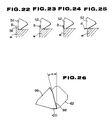
- burr cutting triangular insert 96 having main cutting edges 98 and end cutting edges 100, as shown in Fig.26, being employed instead of the above-mentioned burr cutting insert 26 or 74 in the same manner, may be made therein without departing from the spirit and scope of the invention.
Landscapes
- Engineering & Computer Science (AREA)
- Mechanical Engineering (AREA)
- Milling Processes (AREA)
- Knives (AREA)
Abstract
Description
- The present invention pertains to an insert rotary cutter having at least one first cutter insert and at least one second cutter insert for cutting off burrs attached to a cutter body.
- In processing the surface of a metal workpiece by means of a insert rotary cutter, such as an insert face milling cutter (hereinafter referred to as a face milling cutter) having a plurality of cutter inserts thereon, burrs often remain at the edge of the processed surface of the workpiece. It is thought that the cause of burrs remaining is that the force to bend a small portion of the workpiece adjacent to the edge exceeds the shearing force to cut off the portion, and is that the small portion of the workpiece being bent by the cutting edge of the cutter insert toward the feeding direction of the face milling cutter prior to being cut off thoroughly by the cutting edge. Therefore, to avoid leaving burrs at the edge of the workpiece, the use of cutter inserts is recommended having sharp cutting edges attached on the milling cutter body with a high positive rake angle so as to reduce the force to bend which acts on the workpiece and to enable to cut the burr off thoroughly.
- In addition to the above, it is well-known that a honed edge is inferior to an edge without honing to avoid leaving burrs, even if the honed edge has increased strength and prolonged service life. Accordingly, it is not adequate to employ a cutter insert having an honed edge in the processing to avoid leaving burrs.
- On the contrary, in an insert rotary cutter having the sharp cutting edge without honing attached thereon with a high positive rake angle, the cutting edge tends to chip easily as its strength deteriorates. Therefore, the insert rotary cutter of the kind referred to above, is not available for processing ordinary metal workpieces.
- One conventional rotary cutter designed to leave no burrs on the processed surface of a workpiece is shown in Published Unexamined Japanese Patent Application No.54-137187. This conventional insert rotary cutter has an equal number of first cutting edges and second cutting edges attached to a forward end of a tool body alternately in the circumferencial direction; the second cutting edges are disposed radially inwardly and axially forwardly of the tool body with respect to the first cutting edges, thereby any burrs remaining on the surface processed by the first cutting edges will be swept off by the second cutting edge.
- In the rotary cutter described above, however, new burrs are formed by the second cutting edge. Therefore, the rotary cutter is not capable of preventing the leaving of burrs on the processed surface of the workpiece.
- It is therefore an object of the present invention to provide a insert rotary cutter capable of preventing burrs from remaining on a processed surface of a workpiece.
- According to the present invention, there is provided a insert rotary cutter comprising :
a cutter body having an axis of rotation therethrough and having a forward end portion; and
at least one first cutter insert having more than one main cutting edge and more than one end cutting edge; and
at least one second cutter insert for cutting off a burr having more than one main cutting edge and more than one end cutting edge releasably mounted at the forward end portion of the cutter body, said second cutter insert being disposed so that the main cutting edge thereof has a negative corner angle and the end cutting edge thereof is displaced radially inwardly and axially forwardly of the cutter body, with respect to the end cutting edge of the first cutter insert. -
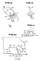
- Fig. 1 is a cross-sectional view of a face milling cutter according to an embodiment of the invention;
- Fig. 2 is a bottom view of the face milling cutter of Fig. 1;
- Fig. 3 is a view seen in the direction indicated by arrow III of Fig. 2;
- Fig. 4 is a view seen in the direction indicated by arrow IV of Fig. 3;
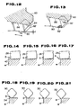
- Fig. 5 is a plan view of a burr cutting insert with a standard cutter insert by alternate-long-and-two-short-dashes line, employed in the face milling cutter of Fig. 1;
- Fig. 6 is a cross-sectional view of a face milling cutter according to a second embodiment of the invention, with a burr cutting insert indicated by alternate-long-and-two-short-dashes line;
- Fig. 7 is a bottom view of the face milling cutter of Fig. 6;
- Fig. 8 is a view seen in the direction indicated by arrow VIII of Fig. 6;
- Fig. 9 is a view seen in the direction indicated by arrow IX of Fig. 8;
- Fig. 10 is an enlarged fragmentary cross-sectional view showing the relative position of a standard cutting insert and a burr cutting insert of Fig.6;
- Fig. 11 is a view seen in the direction indicated by arrow XI of Fig. 6;
- Fig. 12 is a view similar to Fig. 10, but showing a modified pocket of the cutter body;
- fig. 13 is a view similar to Fig. 10, but showing a modified burr cutting insert mounted in the cutter body;
- Fig. 14 to Fig. 17 are schematic cross sectional views showing states in which a workpiece is being cut by a burr cutting insert of Fig. 6;
- Fig. 18 to Fig. 21 are views similar to Fig. 14 to Fig. 17, but show states in which a workpiece is being cut by a cutting insert having positive corner angle;
- Fig. 22 to Fig. 25 are views similar to Fig. 14 to Fig. 17, but show states in which a workpiece is being cut by a cutting insert having a corner angle of 0°; and
- Fig. 26 is a view similar to Fig. 5, but showing a burr cutting triangular insert with the standard cutting edge of the second embodiment indicated by alternate-long-and-two-short-dashes line.
- Referring to Figs. 1 to 5, a face milling cutter according to the present invention comprises a
cutter body 10 of a circular cross-section having an axis of rotation O therethrough and having acircumferential surface 12 and aforward end face 14 disposed in a plan perpendicular to the axis of rotation O. Thecutter body 10 has acentral bore 16 formed axially therethrough. - The
cutter body 10 has a plurality ofpockets 18 arranged in circumferentially unequally spaced relation to one another and formed on a forward end portion thereof so as to open radially outwardly and forwardly therefrom. Each of thepockets 18 has a generally channel-shaped cross-section defined by a pair of circumferentially-facing opposed first andsecond side walls rearward wall 22 andbottom wall 24 interconnecting the first andsecond wall rearward wall 22 at their inner ends. One or a few of thepockets 18 receive burr cutting inserts (second cutter inserts) 26 throughclamp wedge 28 and a screw (not shown) and a plurality of theother pockets 18 receive standard cutter inserts (first cutter insert) 30 throughclamp wedge 32 andscrew 33 interposed therebetween. - The
burr cutting insert 26 comprises a generally square plate defined by a pair of parallel front andrear faces side faces rear faces front face 34. As described by a solid line in Fig. 5, each of theside faces 36 has afirst plane portion 36a directed from each diagonal corner toward the clockwise direction and asecond plane portion 36b. Preferably, thefirst plane portion 36a has a length w ranging from 3 mm to 10 mm. Thefirst plane portion 36a is sloped slightly inwardly in the direction away from thesecond plane portion 36b. A ridge defined by thefront face 34 and thefirst plane portion 36a serves as anend cutting edge 38. A predetermined portion of theother side faces 37 are removed in a V-shape, directed from the corner adjacent to theend cutting edge 38 toward the counterclockwise direction, to providemain cutting edges 40, in such a manner that themain cutting edge 40 is, preferably within a range of from 5° to 30°, tilted inwardly thereof with respect to the line L perpendicular to theend cutting edge 38. - The standard cutter insert 30, as described by the alternate-long-and-two-short-dashes line in Fig. 5, comprises a generally square plate with
front face 42 which has four corners and four ridges and withrear face 43. A predetermined portion of each ridge from the corner, directed toward the counterclockwise direction, serves as amain cutting edge 44. Each portion of the ridge from the corner toward the opposite direction of themain cutting edge 44 serves as anend cutting edge 46. - Each
burr cutting insert 26 is received in arespective pocket 18 in such a manner that thefront face 34 andside face 37 are in contact with thefirst side wall 20 andbottom wall 24 of thepocket 18 respectively. Theburr cutting insert 26 is replaceably held in position by theclamp wedge 28 which is interposed betweenrear face 35 of theinsert 26 and thesecond side wall 21 of thepocket 18 and secured thereto by a threaded screw. Eachstandard cutter insert 30 is received in arespective pocket 18 in such a manner that thefront face 42 and side face are in contact with thefirst side wall 20 andbottom wall 24 of thepocket 18 respectively and is replaceably held in position by theclamp wedge 32 which is received betweenrear face 43 of theinsert 30 and thesecond side wall 21 of thepocket 18 and secured thereto through thescrew 33 threaded thereinto. - These
burr cutting inserts 26 andstandard cutter inserts 30 are so positioned relative to each other that bothend cutting edge 38 andend cutting edge 46 are disposed on each plane perpendicular to the axis of rotation O, hence themain cutting edge 40 of theburr cutting insert 26 has negative corner angle α (which is preferably within a range of from - 5° to - 30°), and theend cutting edge 38 is displaced radially inwardly and axially forwardly of thecutter body 10 with respect to theend cutting edge 46 of the standard cutter insert 30 at a dstance of b and a respectively as shown in Fig. 5. The distance a is preferably within a range of from 0.05 mm to 0.3 mm. - In the face milling cutter constructed as above, since the burr cutting insert 26 and
standard cutter insert 30 are so positioned that themain cutting edge 40 of theburr cutting insert 26 has negative corner angle α, and theend cutting edge 38 is displaced radially inwardly and axially forwardly of thecutter body 10 with respect to theend cutting edge 46 of the standard cutter insert 30, the force to bend a small portion adjacent to the edge of the workpiece acting from the maincutting edge 40 of theburr cutting insert 26 is less than the required shearing force to cut off the portion by themain cutting edge 40. For this reason, as shown in Fig. 14 to Fig. 17, a small portion B of the workpiece W is completely cut off by themain cutting edge 40 of theburr cutting insert 26, and then it is possible to process the surface of the workpiece W without leaving any burrs. - On the contrary, as shown in Fig. 18 to Fig. 21 or in Fig. 22 to Fig. 25, the conventional face milling cutter having cutting insert 50 or 52 with positive corner angle or corner angle 0°, respectively, is not capable of leaving no burrs. This is because the little portion B of workpiece W adjacent to the edge is not cut off thoroughly but is instead bent by the
main cutting edge - In addition, in the embodiment mentioned above, the
end cutting edge 38 of theburr cutting insert 26 is capable of serving as a flat cutting edge if the length of theend cutting edge 38 ranges from 3 mm to 10 mm. Accordingly, it is possible to enhance the precision of the processed surface of the workpiece. - Fig. 6 to Fig. 11 show a second embodiment of the rotary cutter in accordance with the present invention. In this face milling cutter, a plurality of
pockets 61 are arranged in circumferentially unequally spaced relation to one another and formed on a forward end portion ofcutter body 60. - Each
pocket 61 receives standard cutter insert (a first cutter insert) 62, having four main cutting edges 63 and four end cutting edges 64 (with corner angles of approximately 45° ), throughsupport 65, wedge clamps 66 and 67 and screws 68 interposed therebetween. Anadditional pocket 70 is formed inward of thepocket 62 disposed between a pair ofpockets 62 having the widest distance therebetween. A burr cutting insert (a second cutter insert) 74 is received in thepocket 70 throughwedge clamp 72 and screw 73 interposed therebetween. - As shown in Fig. 10 and Fig. 11, the
burr cutting insert 74 comprises a generally parallelogrammatic plate defined by afront face 76 having two pairs ofridges ridges 78 serve as main cutting edges and a predetermined portion of theother ridges 79, preferably having a length w ranging from 3 mm to 10 mm, from each acute angled corner serve as end cutting edges 80. - As shown in Fig. 10, these
burr cutting insert 74 and standard cutter inserts 62 are so positioned to each other that bothend cutting edge 80 andend cutting edge 64 are disposed on each plane perpendicular to the axis of rotation, hence themain cutting edge 78 of theburr cutting insert 74 has a negative corner angle α (which is preferably within a range of from - 5° to - 30°), and theend cutting edge 80 is displaced radially inwardly and axially forwardly of thecutter body 60 with respect to theend cutting edge 64 of theatandard cutter insert 62 at a distance of b and a respectively. The distance a is preferably within a range of from 0.05 mm to 0.3 mm. - Fig. 12 shows a third embodiment of the insert rotary cutter in accordance with the present invention, in which the
cutter body 60 includes apocket 84 opened forwardly and radially both inwardly and outwardly therefrom. The burr cutting insert (a second cutter insert) 74 is received in thepocket 84 in such a manner that a side face is in contact with a slopedrear wall 86 of thepocket 84 and hence, a position of theend cutting edge 80 is adjustable within a distance c by sliding itself along therear wall 86 of thepocket 84. - Fig.13 shows a forth embodiment of the inset rotary cutter in accordance with the present invention, in which a burr cutting insert (a second cutter insert) 90 having the a
portion 92 adjacent to an acute angled corner being made of a sintered super-hardened compact is received in the above-mentionedpocket 84. - While the invention has been particularly shown and described with reference to preferred embodiments thereof, it will be understood that various modifications, for example burr cutting
triangular insert 96, having main cutting edges 98 andend cutting edges 100, as shown in Fig.26, being employed instead of the above-mentionedburr cutting insert
Claims (6)
Applications Claiming Priority (2)
| Application Number | Priority Date | Filing Date | Title |
|---|---|---|---|
| JP268547/88 | 1988-10-25 | ||
| JP63268547A JP2569767B2 (en) | 1988-10-25 | 1988-10-25 | Deburring cutter |
Publications (3)
| Publication Number | Publication Date |
|---|---|
| EP0366111A2 true EP0366111A2 (en) | 1990-05-02 |
| EP0366111A3 EP0366111A3 (en) | 1990-11-14 |
| EP0366111B1 EP0366111B1 (en) | 1993-09-29 |
Family
ID=17460048
Family Applications (1)
| Application Number | Title | Priority Date | Filing Date |
|---|---|---|---|
| EP89119835A Expired - Lifetime EP0366111B1 (en) | 1988-10-25 | 1989-10-25 | Insert rotary cutter |
Country Status (5)
| Country | Link |
|---|---|
| US (1) | US5082400A (en) |
| EP (1) | EP0366111B1 (en) |
| JP (1) | JP2569767B2 (en) |
| KR (1) | KR940006566B1 (en) |
| DE (1) | DE68909556T2 (en) |
Cited By (2)
| Publication number | Priority date | Publication date | Assignee | Title |
|---|---|---|---|---|
| WO1998001253A1 (en) * | 1996-07-05 | 1998-01-15 | Iscar Ltd. | A cutting insert with a rounded corner |
| EP3321017A1 (en) | 2016-11-09 | 2018-05-16 | Sandvik Intellectual Property AB | Milling tool |
Families Citing this family (9)
| Publication number | Priority date | Publication date | Assignee | Title |
|---|---|---|---|---|
| JP2555681Y2 (en) * | 1990-02-23 | 1997-11-26 | 三菱マテリアル株式会社 | Deburring blade |
| JPH088014Y2 (en) * | 1990-11-26 | 1996-03-06 | 三菱マテリアル株式会社 | Throw-away tip |
| JPH06508072A (en) * | 1992-04-28 | 1994-09-14 | ターチャン,マニュエル・シイ | Insulated dry diamond milling machine |
| JP2573001Y2 (en) * | 1993-01-22 | 1998-05-28 | 株式会社小松製作所 | Crankshaft mirror cutter device |
| SE505511C2 (en) * | 1994-12-15 | 1997-09-08 | Sandvik Ab | Milling body and method of manufacture thereof |
| SE512736C2 (en) * | 1997-06-10 | 2000-05-08 | Seco Tools Ab | Face Milling Tools |
| US5967706A (en) * | 1998-09-08 | 1999-10-19 | Kennametal Inc. | High speed milling cutter |
| US6540448B2 (en) | 2001-05-14 | 2003-04-01 | Ingersoll Cutting Tool Company | Cutting tool with improved insert seat arrangement for indexable cutting inserts |
| EP3520692B1 (en) | 2016-09-30 | 2025-08-13 | Sekisui Plastics Co., Ltd. | Gel sheet |
Family Cites Families (14)
| Publication number | Priority date | Publication date | Assignee | Title |
|---|---|---|---|---|
| US1460030A (en) * | 1922-12-21 | 1923-06-26 | Mattson Julius | Milling-machine cutter |
| DE877398C (en) * | 1951-12-07 | 1953-05-21 | Fritz Huerxthal | Cutting tool |
| US2761196A (en) * | 1952-07-23 | 1956-09-04 | Cincinnati Milling Machine Co | Face mill |
| US2949946A (en) * | 1958-03-28 | 1960-08-23 | Donald L Johnson | Means for producing flakes while cutting a flat surface on wood |
| BE627689A (en) * | 1962-05-11 | Derefa Ets | ||
| DE1905038B2 (en) * | 1969-02-01 | 1971-07-08 | SAW BLADE-LIKE CUTTER DISC | |
| BE794130A (en) * | 1972-01-19 | 1973-05-16 | Gen Electric | STRAWBERRY |
| US3818562A (en) * | 1972-07-19 | 1974-06-25 | Kysor Industrial Corp | Cutter body and blade therefor |
| JPS54137187A (en) * | 1978-04-17 | 1979-10-24 | Nissan Motor Co Ltd | Milling machine |
| US4449864A (en) * | 1981-12-07 | 1984-05-22 | Sazzadul Haque | Consumable self-regenerative ledge cutting insert |
| US4529338A (en) * | 1983-03-07 | 1985-07-16 | General Electric Company | Insert arrangement for a milling tool |
| JPS61187618U (en) * | 1985-05-14 | 1986-11-22 | ||
| US4808044A (en) * | 1986-04-30 | 1989-02-28 | Mitsubishi Kinzoku Kabushiki Kaisha | Insert cutter |
| JPS62192815U (en) * | 1986-05-27 | 1987-12-08 |
-
1988
- 1988-10-25 JP JP63268547A patent/JP2569767B2/en not_active Expired - Lifetime
-
1989
- 1989-07-10 KR KR1019890009798A patent/KR940006566B1/en not_active Expired - Lifetime
- 1989-10-23 US US07/425,032 patent/US5082400A/en not_active Expired - Lifetime
- 1989-10-25 DE DE89119835T patent/DE68909556T2/en not_active Expired - Lifetime
- 1989-10-25 EP EP89119835A patent/EP0366111B1/en not_active Expired - Lifetime
Cited By (5)
| Publication number | Priority date | Publication date | Assignee | Title |
|---|---|---|---|---|
| WO1998001253A1 (en) * | 1996-07-05 | 1998-01-15 | Iscar Ltd. | A cutting insert with a rounded corner |
| US5904450A (en) * | 1996-07-05 | 1999-05-18 | Iscar Ltd | Cutting insert with a rounded corner |
| EP3321017A1 (en) | 2016-11-09 | 2018-05-16 | Sandvik Intellectual Property AB | Milling tool |
| WO2018086802A1 (en) | 2016-11-09 | 2018-05-17 | Sandvik Intellectual Property Ab | Milling tool |
| US10870158B2 (en) | 2016-11-09 | 2020-12-22 | Sandvik Intellectual Property Ab | Milling tool |
Also Published As
| Publication number | Publication date |
|---|---|
| KR900006051A (en) | 1990-05-07 |
| DE68909556D1 (en) | 1993-11-04 |
| DE68909556T2 (en) | 1994-03-24 |
| JPH02116408A (en) | 1990-05-01 |
| EP0366111B1 (en) | 1993-09-29 |
| JP2569767B2 (en) | 1997-01-08 |
| EP0366111A3 (en) | 1990-11-14 |
| KR940006566B1 (en) | 1994-07-22 |
| US5082400A (en) | 1992-01-21 |
Similar Documents
| Publication | Publication Date | Title |
|---|---|---|
| EP0342689B1 (en) | Insert rotary cutter | |
| EP0925137B1 (en) | Cutting insert | |
| EP0298154B1 (en) | End mill cutting tool and indexable insert therefor | |
| US4844669A (en) | Insert boring tool and cutting insert therefor | |
| JP3970929B2 (en) | Cutting tips for roughing and precision cutting | |
| EP0094921B1 (en) | Cutting insert | |
| US4645384A (en) | Insert cutter | |
| EP0464825B1 (en) | Throwaway insert and cutting tool therefor | |
| CN108472751B (en) | Cutting inserts and indexable insert cutting tools | |
| JP3057781B2 (en) | Indexable tip | |
| US3818562A (en) | Cutter body and blade therefor | |
| EP0530831B1 (en) | Cutting insert and insert cutter | |
| HU214993B (en) | Removable carbide cutting insert | |
| EP0366111B1 (en) | Insert rotary cutter | |
| GB2064390A (en) | Rotary slot cutting tools | |
| US5004380A (en) | Cutting insert | |
| US3938231A (en) | Center cutting end mill | |
| US4934880A (en) | End mill cutting tool | |
| US4687383A (en) | Insert rotary cutter | |
| EP1112136B1 (en) | High speed milling cutter | |
| EP1200220B1 (en) | Cutting tool assembly | |
| JPH11156624A (en) | Indexable ball end mill | |
| JP2603151B2 (en) | Face milling | |
| JP3246164B2 (en) | Cutting tools | |
| JPH0634893Y2 (en) | End mill |
Legal Events
| Date | Code | Title | Description |
|---|---|---|---|
| PUAI | Public reference made under article 153(3) epc to a published international application that has entered the european phase |
Free format text: ORIGINAL CODE: 0009012 |
|
| AK | Designated contracting states |
Kind code of ref document: A2 Designated state(s): DE FR GB IT SE |
|
| 17P | Request for examination filed |
Effective date: 19900518 |
|
| PUAL | Search report despatched |
Free format text: ORIGINAL CODE: 0009013 |
|
| RHK1 | Main classification (correction) |
Ipc: B23C 5/22 |
|
| AK | Designated contracting states |
Kind code of ref document: A3 Designated state(s): DE FR GB IT SE |
|
| RAP1 | Party data changed (applicant data changed or rights of an application transferred) |
Owner name: MITSUBISHI MATERIALS CORPORATION |
|
| 17Q | First examination report despatched |
Effective date: 19920818 |
|
| GRAA | (expected) grant |
Free format text: ORIGINAL CODE: 0009210 |
|
| AK | Designated contracting states |
Kind code of ref document: B1 Designated state(s): DE FR GB IT SE |
|
| ITF | It: translation for a ep patent filed | ||
| ET | Fr: translation filed | ||
| REF | Corresponds to: |
Ref document number: 68909556 Country of ref document: DE Date of ref document: 19931104 |
|
| PLBE | No opposition filed within time limit |
Free format text: ORIGINAL CODE: 0009261 |
|
| STAA | Information on the status of an ep patent application or granted ep patent |
Free format text: STATUS: NO OPPOSITION FILED WITHIN TIME LIMIT |
|
| 26N | No opposition filed | ||
| EAL | Se: european patent in force in sweden |
Ref document number: 89119835.0 |
|
| PGFP | Annual fee paid to national office [announced via postgrant information from national office to epo] |
Ref country code: SE Payment date: 19960830 Year of fee payment: 8 |
|
| PGFP | Annual fee paid to national office [announced via postgrant information from national office to epo] |
Ref country code: FR Payment date: 19960919 Year of fee payment: 8 |
|
| PGFP | Annual fee paid to national office [announced via postgrant information from national office to epo] |
Ref country code: GB Payment date: 19961004 Year of fee payment: 8 |
|
| PG25 | Lapsed in a contracting state [announced via postgrant information from national office to epo] |
Ref country code: GB Free format text: LAPSE BECAUSE OF NON-PAYMENT OF DUE FEES Effective date: 19971025 |
|
| PG25 | Lapsed in a contracting state [announced via postgrant information from national office to epo] |
Ref country code: SE Free format text: LAPSE BECAUSE OF NON-PAYMENT OF DUE FEES Effective date: 19971026 |
|
| PG25 | Lapsed in a contracting state [announced via postgrant information from national office to epo] |
Ref country code: FR Free format text: THE PATENT HAS BEEN ANNULLED BY A DECISION OF A NATIONAL AUTHORITY Effective date: 19971031 |
|
| GBPC | Gb: european patent ceased through non-payment of renewal fee |
Effective date: 19971025 |
|
| EUG | Se: european patent has lapsed |
Ref document number: 89119835.0 |
|
| REG | Reference to a national code |
Ref country code: FR Ref legal event code: ST |
|
| PG25 | Lapsed in a contracting state [announced via postgrant information from national office to epo] |
Ref country code: IT Free format text: LAPSE BECAUSE OF NON-PAYMENT OF DUE FEES;WARNING: LAPSES OF ITALIAN PATENTS WITH EFFECTIVE DATE BEFORE 2007 MAY HAVE OCCURRED AT ANY TIME BEFORE 2007. THE CORRECT EFFECTIVE DATE MAY BE DIFFERENT FROM THE ONE RECORDED. Effective date: 20051025 |
|
| PGFP | Annual fee paid to national office [announced via postgrant information from national office to epo] |
Ref country code: DE Payment date: 20081022 Year of fee payment: 20 |