EP0366008A2 - Réseau de détecteurs pour dispositifs infrarouges à balayage ligne et rapports vitesse/altitude élevés. - Google Patents
Réseau de détecteurs pour dispositifs infrarouges à balayage ligne et rapports vitesse/altitude élevés. Download PDFInfo
- Publication number
- EP0366008A2 EP0366008A2 EP89119457A EP89119457A EP0366008A2 EP 0366008 A2 EP0366008 A2 EP 0366008A2 EP 89119457 A EP89119457 A EP 89119457A EP 89119457 A EP89119457 A EP 89119457A EP 0366008 A2 EP0366008 A2 EP 0366008A2
- Authority
- EP
- European Patent Office
- Prior art keywords
- detector
- array
- centerline
- alt
- detectors
- Prior art date
- Legal status (The legal status is an assumption and is not a legal conclusion. Google has not performed a legal analysis and makes no representation as to the accuracy of the status listed.)
- Granted
Links
- 238000003491 array Methods 0.000 claims description 10
- 238000012545 processing Methods 0.000 claims description 2
- 238000005070 sampling Methods 0.000 description 7
- 230000003287 optical effect Effects 0.000 description 6
- 230000000694 effects Effects 0.000 description 5
- 238000010586 diagram Methods 0.000 description 4
- 239000000463 material Substances 0.000 description 3
- 229910000661 Mercury cadmium telluride Inorganic materials 0.000 description 2
- MCMSPRNYOJJPIZ-UHFFFAOYSA-N cadmium;mercury;tellurium Chemical compound [Cd]=[Te]=[Hg] MCMSPRNYOJJPIZ-UHFFFAOYSA-N 0.000 description 2
- 239000007795 chemical reaction product Substances 0.000 description 2
- 230000007423 decrease Effects 0.000 description 2
- 238000013461 design Methods 0.000 description 2
- 238000003384 imaging method Methods 0.000 description 2
- 238000002955 isolation Methods 0.000 description 1
- 238000012986 modification Methods 0.000 description 1
- 230000004048 modification Effects 0.000 description 1
- 238000011017 operating method Methods 0.000 description 1
- 230000035515 penetration Effects 0.000 description 1
- 230000002250 progressing effect Effects 0.000 description 1
- 230000000750 progressive effect Effects 0.000 description 1
- 230000005855 radiation Effects 0.000 description 1
- 230000003252 repetitive effect Effects 0.000 description 1
- 230000004083 survival effect Effects 0.000 description 1
Images
Classifications
-
- G—PHYSICS
- G01—MEASURING; TESTING
- G01C—MEASURING DISTANCES, LEVELS OR BEARINGS; SURVEYING; NAVIGATION; GYROSCOPIC INSTRUMENTS; PHOTOGRAMMETRY OR VIDEOGRAMMETRY
- G01C11/00—Photogrammetry or videogrammetry, e.g. stereogrammetry; Photographic surveying
- G01C11/02—Picture taking arrangements specially adapted for photogrammetry or photographic surveying, e.g. controlling overlapping of pictures
-
- H—ELECTRICITY
- H04—ELECTRIC COMMUNICATION TECHNIQUE
- H04N—PICTORIAL COMMUNICATION, e.g. TELEVISION
- H04N25/00—Circuitry of solid-state image sensors [SSIS]; Control thereof
-
- H—ELECTRICITY
- H04—ELECTRIC COMMUNICATION TECHNIQUE
- H04N—PICTORIAL COMMUNICATION, e.g. TELEVISION
- H04N25/00—Circuitry of solid-state image sensors [SSIS]; Control thereof
- H04N25/20—Circuitry of solid-state image sensors [SSIS]; Control thereof for transforming only infrared radiation into image signals
-
- H—ELECTRICITY
- H04—ELECTRIC COMMUNICATION TECHNIQUE
- H04N—PICTORIAL COMMUNICATION, e.g. TELEVISION
- H04N5/00—Details of television systems
- H04N5/30—Transforming light or analogous information into electric information
- H04N5/33—Transforming infrared radiation
Definitions
- This invention relates to the field of infrared sensitive imaging apparatus and more particularly to infrared linescan sensors for airborne reconnaissance.
- Infrared linescan sensors have established themselves as one of the preferred sensors for airborne reconnaissance. They are capable of obtaining valuable tactical reconnaissance imagery during both day and night and under atmospheric conditions which preclude the use of conventional photographic or television-type electro-optical sensors. The value of this tactical imagery has been recognized by potential enemies so that they have equipped their forces with very extensive and effective anti-aircraft capability. Manned and unmanned reconnaissance aircraft have been forced to fly at extremely low altitudes with high velocity in order to increase their probability of survival. The velocity-to-height ratio (V/H) thus becomes a dominant factor in specifying and designing any sensor for such a low altitude, high V/H imagery collection mission.
- V/H velocity-to-height ratio
- the transverse scan is accomplished by the rotation of a facetted scan mirror which has from 2 to 4 facets in typical designs known to the art.
- the transverse scan motion is repetitive as the mirror rotates at constant RPM.
- the scan motion in the other direction is accomplished by the forward motion of the aircraft which is usually taken to be constant.
- V/H very low values of V/H, it is sufficient to scan with a single infrared detector in order to cover the ground below the aircraft in a complete, or contiguously sampled manner.
- the sampling rate must increase so as to avoid having gaps in the alongtrack, or flight, direction.
- infrared detectors In actual practice there is a limit to the number of infrared detectors which can be used. There are a number of reasons why this is so. One of the most important being that of high cost. The infrared detectors used in such systems are themselves very expensive. In addition, each detector requires a preamplifier and, in the typical case of a photoconductive detector, individual detector bias circuits are required as well. The signal chain does not usually stop at the preamplifier. There are postamplifiers with automatic gain control, level clamping and automatic level adjust circuits. It also is necessary to equalize all channels to provide an equal output signal for an equal input radiance. Each of the above-described circuits add cost and complexity to the sensor. Given the above factors, there is a clear need to minimize the number of detector channels in parallel.
- the invention aimes for data rate reduction which matches the resolution in the end product imagery to the requirements of the human interpreter and to the limitations of the real image produced at the sensor focal plane.
- a plurality of detectors are arranged in a linear array in a symmetrical spacing relationship about a centerline.
- the array has an angular overall length sufficient to provide contiguous coverage of the scanning area for a maximum specified V/H ratio.
- the invention consists of a linear detector array, one embodiment of which is illustrated schematically in FIG. 1, which has an angular overall length sufficient to provide contiguous coverage of the ground below the aircraft for the maximum specified V/H.
- the array angular subtense in the alongtrack (ALT) direction is found by dividing the maximum V/H by the number of scans per second.
- the optics will consist of a fixed infinity focus simple telescope placed behind a simple object-space mirror scanner (not shown). It is important to understand the working of the invention to note that any linescanner scans a swath of the earth below the aircraft which contains features or targets at a wide variety of object distances. Most infrared linescanners use one or, at the most, two parabolic mirrors as the focusing element in the optics. The detector focal plane is almost always placed at the infinity focus of the parabola.
- the optics will be in focus only at the high scan angles near the horizons.
- the amount of image defocus will diminish in a nonlinear but progressive manner similar to the focus scale on an ordinary photographic camera.
- the amount of defocus is estimated by virtue of the fact that it is directly proportional to the size of the aperture.
- the aperture of most infrared linescanners is rectangular with the alongtrack (ALT) dimension being larger than the acrosstrack (ACT) dimension.
- the ALT dimension is usually set to be the length of the scan mirror.
- the ALT defocus can be understood to be the projection of this aperture on the ground. For example, if the ALT dimension of the scan mirror is 5 inches, the defocus effect will limit the ALT resolution to this value at the ground regardless of the position of the line-of-sight in the scan and regardless of the altitude.
- the angular measure of this defocus will vary with the slant range to the ground.
- the invention exploits this defocus effect in order to reduce the required numbers of individual detectors in the array.
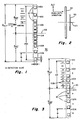
- FIG. 1 illustrates one embodiment of a linear array of detectors as employed by the present invention.
- Other embodiments of the invention may be used and will become apparent to those skilled in the art from considering the examples shown herein. Two such alternate embodiments of the invention are described in detail herein with reference below to FIGS. 2 and 3.
- a linear array of infrared detectors 30 is shown.
- the array comprises a plurality of detectors 10 which are symmetrically located in a linear fashion on either side of a centerline 20.
- the centerline 20 may advantageously coincide with the optical axis of an infrared linescanning system (not shown) in which the invention may be deployed.
- Such a stretched linear array yields about a 2:1 increase in V/H for the same scan rate.
- the plurality of detectors may advantageously number twelve with an equal number of detectors disposed on either side of the centerline 20.
- the individual detector sizes may all be equivalent and the detectors are arranged in a symmetrical linear array with intercell spacings which increase in a nonlinear progression starting from the centerline as the center of symmetry, and progressing outwardly from the centerline.
- Such increasing nonlinear spacing provides optimum sampling by a line scan sensor of the ground below an aircraft once such aircraft is flying at very low altitudes and at high velocities.
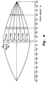
- the V/H ratio is highest at the nadir portion of the scan line and is found to decrease symmetrically at either side of nadir in direct proportion to the cosine of the scan angle difference from nadir, i.e., the nadir is at zero degrees.
- the V/H ratio also decreases in proportion to the altitude, H, assuming a constant aircraft velocity.
- Figure 1 also shows, in dotted line, groupings overlaying detectors and detector spacings, 101-106.
- Each of these groupings represent an equally spaced pixel or resolution element as determined by the scanner aperture operating in a fixed-infinity-focus optical system with a finite object distance, R, which produces a defocus in accordance with equation (1) hereinabove.
- the total detector array spans a distance of 24x in the ALT direction, with each resolution element spanning a distance of 4x (or four times the detector size, x).
- the amount of blur, or loss of resolution, is mathematically described by the point spread function which includes a defocus function as its major component in the application pertinent to the invention.
- the defocus is easily computed with accuracy sufficient for practical uses by noting that the rectangular aperture of the linescanner when projected on the ground at distances R will subtend an angle ⁇ B which is a function of the slant range R.
- the aperture is the superposition of two rectangular apertures (a left and a right aperture) in which the alongtrack ALT aperture is constant and larger than either of the two across track ACT apertures.
- the two ACT apertures are equal other at nadir and differ elsewhere varying with the scan angle from nadir. For the case at nadir, the two equal apertures are superimposed and appear as a single aperture of dimensions equal to one of them.
- the aperture when projected on the ground collects radiance from all points within the aperture projection and focuses this radiance into a single blur pattern in the focal plane. It is, therefore, impossible to distinguish points on the ground which fall within the projected aperture.
- the angular subtense of the projected rectangular aperture is different in the two dimensions at the rectangular aperture because the ALT aperture is always larger than the effective superimposed ACT aperture.
- a single transverse swath could be as wide as from the left horizon to the right horizon or it could be less depending on the application.
- this pattern of defocused pixels which is sampled by scanning the array of the invention. It is a feature of the invention that it is not necessary to provide contiguous detectors in the ALT dimension in order to obtain complete informational sampling of the scene being imaged. It is only necessary to place or scan a detector within a central 2/3 region of the ALT dimension of each blur pattern. It is key feature of the invention that the sampling detectors need not be at the centers of the ALT blur dimension by virtue of our discovery that the defocus optical pattern has an approximately uniform intensity within the central approximate 2/3 region of the pattern. Only the ALT dimension is of concern because the complete ACT dimension of the blur pattern is traversed by any detector sampling that pattern by virtue of the transverse scanning.
- a particular value of the ALT aperture and particular values for the scan period it is advantageous to use a particular value of the ALT aperture and particular values for the scan period to allow the use of six parallel signal channels arising from a choice of six out of a possible twelve detectors in a linear array, it is also possible to choose other values for the ALT aperture, the scan period and the consequent number of channels.
- the choice of other parameter values does not detract from the advantages and features of the invention.
- a smaller value of the ALT aperture, D could be selected which choice would lead to a smaller ALT defocus blur size.
- For the same aircraft V/H ratio and the same scan period it would be possible to resolve a larger number of pixels within the distance moved by the aircraft during a single scan period.
- the detectors may be comprised of any material capable of detecting radiation, including, for example, detectors comprised of mercury cadmium telluride material operating in the photoconductive or photovoltaic mode.
- FIG. 3 an alternate embodiment of the invention is shown in which there are four closely spaced detector elements in the central portion of the twelve element linear array as compared to the six central closely spaced elements of FIG. 1, denoted as Group A.
- each of the detector elements are of equal size denoted by "x”.
- the total alongtrack array subtense, ⁇ ALT is determined by the equation:
- the geometric subtense of the array is slightly less that ⁇ ALT because it is only necessary to sample the defocused resolution elements in order to gain sufficient information for an image.
- Each defocused element subtends an angle, ⁇ , in the alongtrack direction. This is known in the art as the point (or line) spread function.
- the defocus influence produces an approximately uniform intensity distribution over the central 70% of the angle ⁇ ′ so that sampling inside the region provides the required information for a useful image.
- FIG. 3 shows the preferred spacing of the elements wherein the geometric array subtense is 22x and ⁇ ALT is somewhat larger.
- the array is bisected by the centerline 20 into equal lengths of 11x on either side of the centerline.
- the elements are spaced as shown where on each side of the centerline the first two elements are positioned adjacent to one another, the third elements from the centerline are spaced a distance 0.5x from the second elements, the fourth element from the centerline is spaced a distance of 1.0x from the third element, the fifth element is spaced a distance of 1.5x from the fourth element and the last element is spaced a distance of 2x from the fifth element, the total subtense for the elements of the whole linear array of twelve elements being 24x.
- x represents the length or width of the detector elements in either dimension and may also be expressed as IFOV in milliradians.
- x may have a value in the range of about 0.1 milliradian to 1.0 milliradian.
- x may be about 0.3 mr for a typical detector.
- the acronym IFOV is known in the art to represent the geometric instantaneous field-of-view (subtense) of the detector.
- the symmetrical linear array of elements shown in Figure 3 similar to the array shown in Figure 1, comprises six equally spaced resolution elements, 201-206, as depicted by the dotted lines.
- the resolution elements are equally spaced as determined by the scanner aperture operating in a fixed-infinity-focus optical system with a finite object distance, R, which produces a defocus in accordance with the relationship shown in Figure 1. It should be recognized that if additional detectors were placed in the open spaces between the detectors shown in the figures, such additional detectors would not contribute any significant new information to the scanning system.
- FIG. 2 another alternate embodiment of linear detector arrays as implemented by the invention is shown.
- a first linear array for wide mode scanning 40 is shown spaced a suitable distance from a second linear array 50 for fine scanning at two times or more resolution wherein the second linear array 50 is shorter than the first linear array 40.
- the first and second linear arrays are each disposed about a centerline 20 and each have an angular overall length sufficient to provide contiguous coverage of the scanning area for a maximum specified V/H.
- the angular length of the two arrays may be determined as described in the equations referenced above with FIG. 1 or FIG. 3.
- the two arrays 40 and 50, respectively, may advantageously have the size ratio 2:1 but other sizes are possible depending upon the application.
- an embodiment such as is shown in FIG. 2 has the two array patterns placed side-by-side in the same focal plane to allow manual or automatic switching (not shown) from the larger detector size to the smaller for finer resolution.
- the two arrays may be spaced at a distance of S , where S may range from about 6x to x.
- the wide mode array may have a width in the scan direction of about 2x, while the high resolution array may be typically of width 1x.
- the aforementioned spacing and widths are typical values and that other spacings and widths may be used depending upon the scanning system parameters.
- the detectors may be comprised of mercury cadmium telluride material operating in either the photoconductive or the photovoltaic mode.
Landscapes
- Engineering & Computer Science (AREA)
- Multimedia (AREA)
- Signal Processing (AREA)
- Physics & Mathematics (AREA)
- General Physics & Mathematics (AREA)
- Radar, Positioning & Navigation (AREA)
- Remote Sensing (AREA)
- Transforming Light Signals Into Electric Signals (AREA)
- Photometry And Measurement Of Optical Pulse Characteristics (AREA)
- Radiation Pyrometers (AREA)
Applications Claiming Priority (2)
| Application Number | Priority Date | Filing Date | Title |
|---|---|---|---|
| US261354 | 1988-10-24 | ||
| US07/261,354 US4935629A (en) | 1988-10-24 | 1988-10-24 | Detector array for high V/H infrared linescanners |
Publications (3)
| Publication Number | Publication Date |
|---|---|
| EP0366008A2 true EP0366008A2 (fr) | 1990-05-02 |
| EP0366008A3 EP0366008A3 (fr) | 1991-05-08 |
| EP0366008B1 EP0366008B1 (fr) | 1995-01-11 |
Family
ID=22992931
Family Applications (1)
| Application Number | Title | Priority Date | Filing Date |
|---|---|---|---|
| EP89119457A Expired - Lifetime EP0366008B1 (fr) | 1988-10-24 | 1989-10-20 | Réseau de détecteurs pour dispositifs infrarouges à balayage ligne et rapports vitesse/altitude élevés. |
Country Status (3)
| Country | Link |
|---|---|
| US (1) | US4935629A (fr) |
| EP (1) | EP0366008B1 (fr) |
| DE (1) | DE68920544T2 (fr) |
Cited By (4)
| Publication number | Priority date | Publication date | Assignee | Title |
|---|---|---|---|---|
| EP0503103A1 (fr) * | 1989-02-06 | 1992-09-16 | Honeywell Ag | Zoom électronique pour des dispositifs de balayage à ligne pourvus de grand angle de vue |
| EP0510269A1 (fr) * | 1989-12-15 | 1992-10-28 | Loral Infrared & Imaging Systems, Inc. | Dispositif d'analyse de lignes amélioré |
| EP0863667A2 (fr) * | 1997-03-06 | 1998-09-09 | Kabushiki Kaisha Toshiba | Dispositif de prise de vues à l'état solide du type à isolation de surface |
| CN105526963A (zh) * | 2015-12-02 | 2016-04-27 | 北京理工大学 | 可同时测量植被覆盖度和高度的便携式测量仪及测量方法 |
Families Citing this family (13)
| Publication number | Priority date | Publication date | Assignee | Title |
|---|---|---|---|---|
| US5510618A (en) * | 1994-06-23 | 1996-04-23 | The United States Of America As Represented By The Secretary Of The Army | Second generation FLIR common modules |
| US6515285B1 (en) | 1995-10-24 | 2003-02-04 | Lockheed-Martin Ir Imaging Systems, Inc. | Method and apparatus for compensating a radiation sensor for ambient temperature variations |
| US6274869B1 (en) | 1996-06-28 | 2001-08-14 | Lockheed-Martin Ir Imaging Systems, Inc. | Digital offset corrector |
| US5920735A (en) * | 1997-01-16 | 1999-07-06 | Gelphman; Janet L. | Method and apparatus to observe the geometry of relative motion |
| EP1279011A2 (fr) | 2000-05-01 | 2003-01-29 | BAE SYSTEMS Information and Electronic Systems Integration, Inc. | Procedes et appareil de compensation des variations de temperature d'un capteur de rayonnement |
| US7893957B2 (en) * | 2002-08-28 | 2011-02-22 | Visual Intelligence, LP | Retinal array compound camera system |
| US8483960B2 (en) * | 2002-09-20 | 2013-07-09 | Visual Intelligence, LP | Self-calibrated, remote imaging and data processing system |
| US7725258B2 (en) * | 2002-09-20 | 2010-05-25 | M7 Visual Intelligence, L.P. | Vehicle based data collection and processing system and imaging sensor system and methods thereof |
| USRE49105E1 (en) | 2002-09-20 | 2022-06-14 | Vi Technologies, Llc | Self-calibrated, remote imaging and data processing system |
| EP1540937A4 (fr) * | 2002-09-20 | 2008-11-12 | M7 Visual Intelligence Lp | Systeme de traitement et de collecte de donnees concernant un vehicule |
| US7030378B2 (en) * | 2003-08-05 | 2006-04-18 | Bae Systems Information And Electronic Systems Integration, Inc. | Real-time radiation sensor calibration |
| US7763857B2 (en) * | 2008-02-21 | 2010-07-27 | Raytheon Company | Infrared imaging optical system with varying focal length across the field of view |
| US8830316B2 (en) | 2010-10-01 | 2014-09-09 | Brimrose Technology Corporation | Unattended spatial sensing |
Citations (7)
| Publication number | Priority date | Publication date | Assignee | Title |
|---|---|---|---|---|
| US3889117A (en) * | 1971-04-29 | 1975-06-10 | Cincinnati Electronics Corp | Tapered detector scanning array system |
| DE2652586A1 (de) * | 1975-04-29 | 1978-05-24 | Elektro Optik Gmbh & Co Kg | Verfahren zur erzeugung und wiedergabe thermografischer bilder |
| US4118733A (en) * | 1976-03-30 | 1978-10-03 | Elliott Brothers (London) Limited | Surveillance arrangement including a television system and infrared detector means |
| JPS58212269A (ja) * | 1982-06-03 | 1983-12-09 | Hayashi Nakagome | 撮像素子 |
| FR2547426A1 (fr) * | 1983-06-08 | 1984-12-14 | Matra | Dispositif de prise de vues aeriennes a basse altitude |
| JPS6112178A (ja) * | 1984-06-26 | 1986-01-20 | Mitsubishi Electric Corp | 固体撮像装置 |
| US4683498A (en) * | 1986-04-21 | 1987-07-28 | Rca Corporation | Compatible wide-screen television system camera |
Family Cites Families (1)
| Publication number | Priority date | Publication date | Assignee | Title |
|---|---|---|---|---|
| NL7606899A (nl) * | 1976-06-24 | 1977-12-28 | Optosche Ind De Oude Delft Nv | Opto-elektrisch detectiestelsel. |
-
1988
- 1988-10-24 US US07/261,354 patent/US4935629A/en not_active Expired - Fee Related
-
1989
- 1989-10-20 EP EP89119457A patent/EP0366008B1/fr not_active Expired - Lifetime
- 1989-10-20 DE DE68920544T patent/DE68920544T2/de not_active Expired - Fee Related
Patent Citations (7)
| Publication number | Priority date | Publication date | Assignee | Title |
|---|---|---|---|---|
| US3889117A (en) * | 1971-04-29 | 1975-06-10 | Cincinnati Electronics Corp | Tapered detector scanning array system |
| DE2652586A1 (de) * | 1975-04-29 | 1978-05-24 | Elektro Optik Gmbh & Co Kg | Verfahren zur erzeugung und wiedergabe thermografischer bilder |
| US4118733A (en) * | 1976-03-30 | 1978-10-03 | Elliott Brothers (London) Limited | Surveillance arrangement including a television system and infrared detector means |
| JPS58212269A (ja) * | 1982-06-03 | 1983-12-09 | Hayashi Nakagome | 撮像素子 |
| FR2547426A1 (fr) * | 1983-06-08 | 1984-12-14 | Matra | Dispositif de prise de vues aeriennes a basse altitude |
| JPS6112178A (ja) * | 1984-06-26 | 1986-01-20 | Mitsubishi Electric Corp | 固体撮像装置 |
| US4683498A (en) * | 1986-04-21 | 1987-07-28 | Rca Corporation | Compatible wide-screen television system camera |
Non-Patent Citations (2)
| Title |
|---|
| PATENT ABSTRACTS OF JAPAN, vol. 10, no. 158 (E-409)[52], 6th June 1986; & JP-A-61 012 178 (MITSUBISHI DENKI K.K.) 20-01-1986 * |
| PATENT ABSTRACTS OF JAPAN, vol. 8, no. 63 (E-233)[1500], 24th March 1984; & JP-A-58 212 269 (HAYASHI NAKAGOME) 09-12-1983 * |
Cited By (7)
| Publication number | Priority date | Publication date | Assignee | Title |
|---|---|---|---|---|
| EP0503103A1 (fr) * | 1989-02-06 | 1992-09-16 | Honeywell Ag | Zoom électronique pour des dispositifs de balayage à ligne pourvus de grand angle de vue |
| EP0510269A1 (fr) * | 1989-12-15 | 1992-10-28 | Loral Infrared & Imaging Systems, Inc. | Dispositif d'analyse de lignes amélioré |
| EP0863667A2 (fr) * | 1997-03-06 | 1998-09-09 | Kabushiki Kaisha Toshiba | Dispositif de prise de vues à l'état solide du type à isolation de surface |
| EP0863667A3 (fr) * | 1997-03-06 | 1999-04-21 | Kabushiki Kaisha Toshiba | Dispositif de prise de vues à l'état solide du type à isolation de surface |
| US6333760B1 (en) | 1997-03-06 | 2001-12-25 | Kawasaki Kaisha Toshiba | Area isolation type solid-state image pickup device for increasing the usage of the element formation surface of a semiconductor chip |
| CN105526963A (zh) * | 2015-12-02 | 2016-04-27 | 北京理工大学 | 可同时测量植被覆盖度和高度的便携式测量仪及测量方法 |
| CN105526963B (zh) * | 2015-12-02 | 2017-09-12 | 北京理工大学 | 可同时测量植被覆盖度和高度的便携式测量仪及测量方法 |
Also Published As
| Publication number | Publication date |
|---|---|
| EP0366008A3 (fr) | 1991-05-08 |
| DE68920544T2 (de) | 1995-05-18 |
| US4935629A (en) | 1990-06-19 |
| EP0366008B1 (fr) | 1995-01-11 |
| DE68920544D1 (de) | 1995-02-23 |
Similar Documents
| Publication | Publication Date | Title |
|---|---|---|
| US4935629A (en) | Detector array for high V/H infrared linescanners | |
| US5692062A (en) | Electro-optical imaging array with profiled foward motion compensation | |
| US6130705A (en) | Autonomous electro-optical framing camera system with constant ground resolution, unmanned airborne vehicle therefor, and methods of use | |
| US4527055A (en) | Apparatus for selectively viewing either of two scenes of interest | |
| US4908705A (en) | Steerable wide-angle imaging system | |
| US5155597A (en) | Electro-optical imaging array with motion compensation | |
| JP2783522B2 (ja) | 衛星焦点平面アレイイメージ装置 | |
| US6826358B2 (en) | Dual band hyperspectral framing reconnaissance camera | |
| US8907288B2 (en) | Digitally scanned multi-cell electro-optic sensor | |
| US5055683A (en) | Line scanner | |
| Baumgardner et al. | Monochromatic imaging instrumentation for applications in aeronomy of the Earth and planets | |
| US6658207B1 (en) | Method of framing reconnaissance with motion roll compensation | |
| US6366734B1 (en) | Method of forward motion compensation in an aerial reconnaissance camera | |
| US4989086A (en) | Ultra wide field-of-regard multispectral imaging radiometer | |
| Lareau | Electro-optical imaging array with motion compensation | |
| US7949241B2 (en) | Anamorphic focal array | |
| WO2002019030A9 (fr) | Camera de reconnaissance a double bande avec compensation du roulis | |
| EP1416312B1 (fr) | Système de capteur de balayage à champ large | |
| Strojnik et al. | Push-broom reconnaissance camera with time expansion for a (Martian) landing-site certification | |
| Lareau | Optimum coverage EO framing camera | |
| McCracken | IRLS: basic design and future challenges | |
| Thomson | Aerospace Report Number 1 | |
| Slater | A review of recent developments in multiband cameras | |
| Joseph et al. | Optical infrared remote sensors | |
| Gupta et al. | Multispectral Imaging Systems |
Legal Events
| Date | Code | Title | Description |
|---|---|---|---|
| PUAI | Public reference made under article 153(3) epc to a published international application that has entered the european phase |
Free format text: ORIGINAL CODE: 0009012 |
|
| AK | Designated contracting states |
Kind code of ref document: A2 Designated state(s): DE GB |
|
| PUAL | Search report despatched |
Free format text: ORIGINAL CODE: 0009013 |
|
| AK | Designated contracting states |
Kind code of ref document: A3 Designated state(s): DE GB |
|
| 17P | Request for examination filed |
Effective date: 19911004 |
|
| 17Q | First examination report despatched |
Effective date: 19930401 |
|
| RAP1 | Party data changed (applicant data changed or rights of an application transferred) |
Owner name: LORAL INFRARED & IMAGING SYSTEMS, INC. |
|
| GRAA | (expected) grant |
Free format text: ORIGINAL CODE: 0009210 |
|
| AK | Designated contracting states |
Kind code of ref document: B1 Designated state(s): DE GB |
|
| REF | Corresponds to: |
Ref document number: 68920544 Country of ref document: DE Date of ref document: 19950223 |
|
| PLBE | No opposition filed within time limit |
Free format text: ORIGINAL CODE: 0009261 |
|
| STAA | Information on the status of an ep patent application or granted ep patent |
Free format text: STATUS: NO OPPOSITION FILED WITHIN TIME LIMIT |
|
| 26N | No opposition filed | ||
| PGFP | Annual fee paid to national office [announced via postgrant information from national office to epo] |
Ref country code: DE Payment date: 19971231 Year of fee payment: 9 |
|
| PGFP | Annual fee paid to national office [announced via postgrant information from national office to epo] |
Ref country code: GB Payment date: 19980102 Year of fee payment: 9 |
|
| PG25 | Lapsed in a contracting state [announced via postgrant information from national office to epo] |
Ref country code: GB Free format text: LAPSE BECAUSE OF NON-PAYMENT OF DUE FEES Effective date: 19981020 |
|
| GBPC | Gb: european patent ceased through non-payment of renewal fee |
Effective date: 19981020 |
|
| PG25 | Lapsed in a contracting state [announced via postgrant information from national office to epo] |
Ref country code: DE Free format text: LAPSE BECAUSE OF NON-PAYMENT OF DUE FEES Effective date: 19990803 |