EP0365909A2 - Tumbler-actuated push button element - Google Patents
Tumbler-actuated push button element Download PDFInfo
- Publication number
- EP0365909A2 EP0365909A2 EP89118763A EP89118763A EP0365909A2 EP 0365909 A2 EP0365909 A2 EP 0365909A2 EP 89118763 A EP89118763 A EP 89118763A EP 89118763 A EP89118763 A EP 89118763A EP 0365909 A2 EP0365909 A2 EP 0365909A2
- Authority
- EP
- European Patent Office
- Prior art keywords
- cam
- axial end
- guide ring
- contact
- actuating
- Prior art date
- Legal status (The legal status is an assumption and is not a legal conclusion. Google has not performed a legal analysis and makes no representation as to the accuracy of the status listed.)
- Granted
Links
Images


Classifications
-
- H—ELECTRICITY
- H01—ELECTRIC ELEMENTS
- H01H—ELECTRIC SWITCHES; RELAYS; SELECTORS; EMERGENCY PROTECTIVE DEVICES
- H01H23/00—Tumbler or rocker switches, i.e. switches characterised by being operated by rocking an operating member in the form of a rocker button
- H01H23/02—Details
- H01H23/12—Movable parts; Contacts mounted thereon
- H01H23/16—Driving mechanisms
- H01H23/164—Driving mechanisms with rectilinearly movable member carrying the contacts
Definitions
- the invention relates to an electrical switch in which the pivoting movement of an actuating element is converted into a linear movement of a contact carrier of an electrical contact module.
- US-A-4504713 discloses a modular push-button switch which has a contact module which consists of a contact carrier which is set up for elastic reciprocating movement between predetermined axial limits in a housing.
- a cover module assigned to the contact module contains a push button which can be moved manually between predetermined axial limits.
- the invention is therefore based on the object of providing an electrical switch according to the preamble in the form of a toggle switch which can be produced with modules of the type of switch described in the prior art.
- the electrical switch has a contact module, an actuator module and means for the simultaneous attachment of the two modules to a front panel.
- the manufacture and assembly of the actuator module facilitated in that the elements of the actuator module are held in the desired relative position to one another by the same fastening means, by means of which the two modules are fastened together.
- the manufacture and assembly of the contact module is facilitated by the fact that the contact module of the switch described in the prior art can be used, only a recess having to be made in the movable contact carrier for receiving a cam.
- the actuator module has a guide ring, an actuating lever and a guide ring adapter.
- the operating lever is sandwiched between the guide ring and the guide ring adapter, these elements being held in the desired position by friction until final assembly.
- the actuator module is coupled to the contact module modified by the cam, the elements of the contact module are held securely in the assembled position by the fastening means of the two modules and the front plate.
- the toggle switch 20 denotes an electrical toggle switch for two switch positions, which is composed of a contact module 22 and an actuator module 24.
- the elements of the toggle switch 20 described in more detail below can consist of suitable high-strength plastics or, if no electrical insulation is required, of suitable metals.
- parts subject to friction during the switching operation can be made of nylon, and the housing and other non-subject parts can be made of polycarbonate-based plastics.
- the toggle switch 20 is set up for mounting on a front panel 26 which has inner and outer sides or surfaces 28 and 30 and an opening 32 which extends between the sides 28 and 30.
- the toggle switch 20 is fastened to the inner side 28 of the front plate 26 by means of fastening means 34 which have first and second threaded columns 36 and 38, which are fastened to the inner side 28, and can be screwed onto the threaded columns 36 and 38 Have nuts 40 and 42.
- the fastening means 34 simultaneously fasten the contact module and the actuator module, the latter being clamped between the contact module 22 and the inner side 28 of the front plate 26.
- the elements of the actuator module 24 are also held in the desired position by means of the frictional connection effected by the fastening means 34, which simplifies the manufacture and assembly of the toggle switch 20.
- the actuator module 24 consists of a guide ring 44, an actuating lever 46 and a guide ring adapter 48.
- the guide ring 44 adapts the actuator module 24 to the front plate 26, while the guide ring adapter 48 adapts the actuator module 24 to the contact module 22.
- the guide ring 44 has a first and a second axial end 50 and 52 relative to a longitudinal axis 54 of the toggle switch 20, which is concentric with the opening 32 of the front plate 26.
- the guide ring 44 has a flange 56 lying in the middle between its two ends, a first and a second cylindrical projection 58 and 60, which extend from the flange 56 in the direction of the first and second axial Extend ends 50 and 52, and an opening 62 extending between the axial ends 50 and 52.
- the cylindrical extension 58 has a first and a second recess 64 and 66, respectively, which are arranged on opposite sides of the opening 62 and extend in the same direction.
- the recesses 64 and 66 have straight, parallel sides which end in cross section in a semicircular surface. As can be seen from FIG. 3, in the recess 64 the straight surfaces are designated 68 and 70 and the semicircular surface 72, the semicircular surface 72 having a central axis 73.
- the cylindrical extension 60 extends perpendicularly from the flange 56 by a predetermined length, designated 74, which is preferably equal to the thickness of the front plate 26; for example 3.2 mm.
- the extension 60 then borders on spherical surfaces 76 and 78, which are separated by the opening 62 and shallow recesses 80 and 82, which run perpendicular to the longitudinal axis 54.
- the opening 62 at the second axial end 52 has two separate flat surfaces 84 and 86, which are chamfered at an angle 88 of 30 degrees.
- the tapered surfaces end when they reach the flat recesses 80 and 82, the opening 62 progressively being defined towards the first axial end 50 by surfaces 90 and 92 running parallel to one another.
- the opening 62 begins at the flat recesses 80 and 82 and the flat surfaces 94 and 96 extending at an angle of 30 degrees to the longitudinal axis 54.
- the flat surfaces 94 and 96 end at one end from the longitudinal axis 54 from outward-facing sheets of short length.
- the arcuate surfaces 98 and 100 formed in this way adjoin flat surfaces 102 and 104 which run parallel to one another and extend to the first axial end 50 of the guide ring 44.
- the actuating lever 46 has a first and a second axial end 106 and 108, respectively.
- the first axial end 106 serves as an actuation cam and the second axial end 108 serves as a handle for the manually actuable switch 20.
- a first and a second pivot 110 and 112 extend from opposite sides of the actuation lever 46, lying on a common axis 114 , outward.
- the diameters of the pivot pins 110 and 112 are dimensioned such that they lie closely in the recesses 64 and 66, respectively, the recesses 64 and 66 serving as bearings for the pivoting movement of the actuating lever 46 about the axis 114.
- the Actuating lever 46 begins at the first axial end 106 with a radius of, for example, 1.6 mm, which merges into flat, parallel sides 116 and 118 which extend over a certain length towards the second axial end 108.
- the sides 116 and 118 meet flat surfaces 120 and 122, respectively, which are beveled outward at a certain angle, for example 105 degrees.
- the flat surfaces 120 and 122 meet arcuate surfaces 124 and 126, respectively, which have a certain radius, for example 7.9 mm.
- the arcuate surfaces 124 and 126 are immediately adjacent to the arcuate surfaces 98 and 100 after the installation of the operating lever 46 in the guide ring 44.
- the arcuate surfaces 124 and 126 meet flat, parallel surfaces 128 and 130, which extend to the second axial end 108 and merge into a radius of 3.2 mm, for example.
- the guide ring adapter 48 has fastening eyes in which holes 132 and 134 are arranged for receiving the threaded columns 36 and 38, respectively.
- the guide ring adapter 48 has a first and a second axial end 136 or 138 and a wall 140 arranged at the first axial end 136.
- the wall 140 has a surface 142 which delimits a circular opening lying coaxially to the longitudinal axis 54.
- the guide ring adapter 48 also has a surface 144 that defines a circular opening that begins at the second axial end 138 and extends to the wall 140.
- the opening defined by the surface 142 is dimensioned such that the actuating cam 106 of the actuating lever 46 can protrude through and pivot in a specific area.
- the opening defined by the surface 144 is dimensioned such that the cylindrical extension 58 of the guide ring 44 can be accommodated in a closely fitting but sliding manner.
- the second axial end 138 is recessed by the thickness of the flange 56 of the guide ring 44, thereby forming upper and lower lips 146 and 148, respectively.
- the distance of the lips 146 and 148 from one another are dimensioned such that the flange 56 can be pushed in tightly therebetween, a projection 150 located on the lip 148 engaging in a groove 152 or 154 provided on the flange 56, so that the guide ring 44 is aligned concentrically with the longitudinal axis 54 .
- the contact module 22 has a housing 156 with attachment eyes, in which holes 158 and 160 are provided for receiving the threaded columns 36 and 38 of the front plate 26, and fixed electrical contacts 162 and 164.
- the fixed electrical contacts can normally be open, closed, or one open and the other closed. In the exemplary embodiment, contact 162 may be closed and contact 164 may be open.
- the contact module 22 also has a contact carrier 166 with a first and a second axial end 168 and 170, electrical contacts 172 and 174 being arranged at the first axial end 168 and cooperating with the fixed contacts 162 and 164, respectively.
- the contact carrier 166 is guided in a straight line, movable along the longitudinal axis 54 within the housing 156 by means of ribs which engage in grooves.
- Compression springs 176 are arranged between the housing and the first axial end 168, which press the contact carrier 166 into a first axial limit position, which, as can be seen in more detail from the above-mentioned patent specification, is provided by contact of a leg 178 of the contact carrier 166 with a housing surface.
- a second axial basis is achieved after overcoming the spring force of the compression springs 176, the contact carrier 166 abutting against a wall part of the housing 156, as also shown in the above-mentioned patent.
- the second axial end 170 of the contact carrier 166 has a cylindrical recess 180, which extends inward from end 170 by a certain length.
- An axially extending groove 182 is provided in the wall which delimits the recess 180.
- a cam 184 shown in FIGS. 2, 3, 10 and 11 is arranged in the recess 180 of the contact carrier 166.
- Both the cam 184 and the actuating lever 46 are preferably made of nylon because this material is well suited for parts subject to dynamic friction.
- the cam 184 which is essentially cylindrical in shape, has a first and a second end 186 or 188, a recess 189 being provided at the second end 188.
- the diameter of the cam 184 is to be dimensioned such that it can be press-fit into the recess 180 of the contact carrier 166, the outer surface of the cam 184 having a rib 191 which engages in the groove 183 so that the cam 184 is precisely aligned becomes.
- the recess 189 is formed from a first and a second step 190 and 192 which extend inwards from the second axial end 188 and serve as a first and second time limit.
- the first and second stages 190 and 192 are connected by an inclined cam surface 194.
- grooves 196 and 198 are arranged which ensure secure positions of the actuating cam 106 of the actuating lever 46, so that when switching over it can be felt that the actuating lever 46 has changed from one position to the other .
- the depth of the recess 189 is chosen so that the springs 176 are only slightly compressed when the actuating cam 106 is engaged in the groove 198 adjacent to the step 192.
- the spring force is dimensioned so that the actuating cam 106 is held in the groove 198, whereby a completely closed state of the normally closed contacts and the desired distance between the normally open contacts is ensured. If the operating lever 46 is moved such that the Actuating cam 106 is guided over the cam surface 194 to the groove 196 adjacent to the first lateral step 190, the contact carrier 166 is pushed against the compression springs 176 into a position in which the normally closed contact is completely open and the normally open contact is completely closed. The pressure exerted by the compression springs 176 holds the actuating cam 106 of the actuating lever 46 in the groove 196, so that the position of the switch 20 set by hand is retained.
- the manufacture and assembly of the switch 20 is facilitated by the fastening arrangement provided, since the switch is mounted on a front plate 26, by means of which the actuating elements of the actuating element module 24 are held in the desired relative position to one another.
- the elements of actuator module 24 can be frictionally assembled, with guide ring 44 and guide adapter 48 cooperating to form a bearing for pivots 110 and 112 which, when actuator module 24 is fixed by fasteners 34 is clamped between the front plate 26 and the contact module 22, is finally fixed.
- the handle end 108 of the actuating lever 46 is inserted into the opening 62 of the guide ring 44 until the pivot pins 110 and 112 are inserted into the recesses 64 and 66 of the guide ring 44.
- Spherical surfaces 76 and 78 protect handle end 108 from accidental actuation, with inclined surfaces 84 and 86 and flat recesses 80 and 82 leaving sufficient room for manual actuation of handle end 108.
- the flat surfaces 94 and 96 provide a firm stop for the handle end 108 because its sides 128 and 130 abut against the surfaces 94 and 96 when pivoted, which limits the range of the pivoting movement.
- the guide ring adapter 48 is placed on the guide ring 44 pushed by inserting the cylindrical extension 58 into the opening of the guide ring adapter 48 defined by the surface 144.
- the dimensions of the parts to be assembled are such that the elements of the actuator module 24 are held in the assembled position by friction until the rear wall 140 of the guide ring adapter 48 is pressed against the pivot pins 110 and 112 of the actuating lever 46.
- the actuator module 24 is then assembled with the contact module 22 such that projections 200 attached to the housing 156 are snugly inserted into openings of the first axial end 136 of the guide ring adapter 48, the actuator and contact modules being held in this position by friction.
- the tension of the compression springs 176 exerts pressure on the guide ring 44, so that the latter has the tendency to move forward slightly with the actuating lever 46.
- the elements of the actuator module 24 remain coupled even if the guide ring 44 and the guide ring adapter 48 are not firmly pressed together.
- pressure is exerted on the actuating lever 46 so that it is firmly seated, regardless of the switch position.
- the final assembly is done by pushing the threaded column 36 through the aligning holes 132 and 158, and the threaded column 38 through the aligning holes 134 and 160 of the guide ring adapter 48 and the housing 156, with the cylindrical extension 60 of the guide ring 44 into the opening 32 of the front panel 26 is fitted.
- the actuator module 24 is firmly clamped between the inner surface 28 of the front plate 26 and the contact module 22, the flange 56 of the guide ring 44 being pressed firmly against the guide ring adapter 48, so that the Bearing for the pivot pins 110 and 112 is finally fixed by the interaction of the surfaces of the guide ring 44 and the guide ring adapter 48.
- the fastening means 34 thus also hold the switch 20 on the front plate 26.
Landscapes
- Tumbler Switches (AREA)
- Push-Button Switches (AREA)
- Switches With Compound Operations (AREA)
- Mechanisms For Operating Contacts (AREA)
- Valve-Gear Or Valve Arrangements (AREA)
- Valve Device For Special Equipments (AREA)
- Rotary Switch, Piano Key Switch, And Lever Switch (AREA)
Abstract
Description
Die Erfindung betrifft einen elektrischen Schalter, bei welchem die Schwenkbewegung eines Betätigungsgliedes in eine geradlinige Bewegung eines Kontaktträgers eines elektrischen Kontaktmoduls umgesetzt wird.The invention relates to an electrical switch in which the pivoting movement of an actuating element is converted into a linear movement of a contact carrier of an electrical contact module.
Mit der US-A-4504713 ist ein in Modul-Bauweise ausgeführter elektrischer Druckknopfschalter bekannt geworden, der einen Kontaktmodul aufweist, welcher aus einem Kontaktträger besteht, der für elastische Hin- und Herbewegung zwischen vorherbestimmten axialen Begrenzungen in einem Gehäuse eingerichtet ist. Ein dem Kontaktmodul zugeordneter Abdeckmodul enthält einen Druckknopf, welcher von Hand zwischen vorherbestimmten axialen Begrenzungen bewegt werden kann.US-A-4504713 discloses a modular push-button switch which has a contact module which consists of a contact carrier which is set up for elastic reciprocating movement between predetermined axial limits in a housing. A cover module assigned to the contact module contains a push button which can be moved manually between predetermined axial limits.
In Bezug auf die Anwendung elektrischer Schalter, besteht auch Bedarf an Schlüsselschaltern, Kippschaltern, usw. Für Fabrikation und Montage ist es wünschenswert, dass verschiedene Arten elektrischer Schalter aus den gleichen Modulen oder aus gleichen, leicht abgeänderten Modulen zusammengebaut werden können.With regard to the use of electrical switches, there is also a need for key switches, toggle switches, etc. For manufacturing and assembly, it is desirable that different types of electrical switches can be assembled from the same modules or from the same, slightly modified modules.
Der Erfindung liegt daher die Aufgabe zugrunde, einen elektrischen Schalter gemäss Oberbegriff in Form eines Kippschalters zu schaffen, welcher mit Modulen, der im Stand der Technik beschriebenen Schalterart hergestellt werden kann.The invention is therefore based on the object of providing an electrical switch according to the preamble in the form of a toggle switch which can be produced with modules of the type of switch described in the prior art.
Diese Aufgabe wird durch die im Patentanspruch 1 gekennzeichnete Erfindung gelöst.This object is achieved by the invention characterized in claim 1.
Hierbei weist der elektrische Schalter einen Kontaktmodul, einen Betätigungsgliedmodul und Mittel für die gleichzeitige Befestigung der beiden Module an einer Frontplatte auf. Die Herstellung und Montage des Betätigungsgliedmoduls wird erleichtert, in dem die Elemente des Betätigungsgliedmoduls durch die gleichen Befestigungsmittel in der gewünschten relativen Lage zueinander gehalten werden, durch welche die beiden Module zusammen befestigt werden. Die Herstellung und Montage des Kontaktmoduls wird dadurch erleichtert, dass der Kontaktmodul des im Stand der Technik beschriebenen Schalters verwendet werden kann, wobei lediglich im bewegbaren Kontaktträger eine Vertiefung für die Aufnahme eines Nockens angebracht werden muss.Here, the electrical switch has a contact module, an actuator module and means for the simultaneous attachment of the two modules to a front panel. The manufacture and assembly of the actuator module facilitated in that the elements of the actuator module are held in the desired relative position to one another by the same fastening means, by means of which the two modules are fastened together. The manufacture and assembly of the contact module is facilitated by the fact that the contact module of the switch described in the prior art can be used, only a recess having to be made in the movable contact carrier for receiving a cam.
Der Betätigungsgliedmodul weist einen Führungsring, einen Betätigungshebel und einen Führungsringadapter auf. Der Betätigungshebel ist sandwichartig zwischen dem Führungsring und dem Führungsringadapter angeordnet, wobei diese Elemente bis zur endgültigen Montage durch Reibung in der gewünschten Position gehalten werden. Wenn der Betätigungsgliedmodul mit dem durch den Nocken modifizierten Kontaktmodul gekoppelt ist, werden die Elemente des Kontaktmoduls durch die Befestigungsmittel der beiden Module und der Frontplatte sicher in der montierten Position gehalten.The actuator module has a guide ring, an actuating lever and a guide ring adapter. The operating lever is sandwiched between the guide ring and the guide ring adapter, these elements being held in the desired position by friction until final assembly. When the actuator module is coupled to the contact module modified by the cam, the elements of the contact module are held securely in the assembled position by the fastening means of the two modules and the front plate.
Im folgenden wird die Erfindung anhand eines auf der Zeichnung dargestellten Ausführungsbeispiels näher erläutert.The invention is explained in more detail below on the basis of an exemplary embodiment shown in the drawing.
Es zeigen:
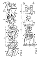
- Fig. 1 eine perspektivische Ansicht des erfindungsgemässen elektrischen Schalters,
- Fig. 2 eine perspektivische Ansicht des elektrischen Schalters gemäss Fig. 1, in Explosions-Darstellung,
- Fig. 3 eine Seitenansicht des elektrischen Schalters gemäss Fig. 1, in Explosions-Darstellung,
- Fig. 4 eine Frontansicht eines Führungsringes des elektrischen Schalters gemäss Fig. 1, 2 und 3,
- Fig. 5 eine Rückansicht des Führungsringes gemäss Fig. 4,
- Fig. 6 einen Schnitt des Führungsringes gemäss der Linie VI-VI der Fig. 4,
- Fig. 7 einen Grundriss eines Betätigungshebels des elektrischen Schalters gemäss Fig. 1, 2 und 3,
- Fig. 8 eine Rückansicht des Betätigungshebels gemäss Fig. 7,
- Fig. 9 einen Schnitt des Betätigungshebels gemäss der Linie IX-IX der Fig. 7,
- Fig. 10 eine Ansicht eines Nockens des elektrischen Schalters gemäss den Fig. 2 und 3, und
- Fig. 11 einen Schnitt des Nockens gemäss der Linie XI-XI der Fig. 10.
- 1 is a perspective view of the electrical switch according to the invention,
- 2 is a perspective view of the electrical switch according to FIG. 1, in an exploded view,
- 3 is a side view of the electrical switch according to FIG. 1, in an exploded view,
- 4 shows a front view of a guide ring of the electrical switch according to FIGS. 1, 2 and 3,
- 5 shows a rear view of the guide ring according to FIG. 4,
- 6 shows a section of the guide ring according to line VI-VI of FIG. 4,
- 7 is a plan view of an operating lever of the electrical switch according to FIGS. 1, 2 and 3,
- 8 is a rear view of the operating lever according to FIG. 7,
- 9 shows a section of the actuating lever along the line IX-IX of FIG. 7,
- 10 is a view of a cam of the electrical switch according to FIGS. 2 and 3, and
- 11 shows a section of the cam along the line XI-XI of FIG. 10.
In der Fig. 1 ist mit 20 ein elektrischer Kippschalter für zwei Schaltstellungen bezeichnet, der aus einem Kontaktmodul 22 und einem Betätigungsgliedmodul 24 zusammengesetzt ist. Die nachstehend näher beschriebenen Elemente des Kippschalters 20 können aus geeigneten hochfesten Kunststoffen oder, wenn keine elektrische Isolation erforderlich ist, aus geeigneten Metallen bestehen. Beispielweise können Teile, die bei der Schaltoperation der Reibung unterworfen sind aus Nylon, und das Gehäuse sowie andere, nicht der Reibung unterworfene Teile aus Kunststoffen auf Polycarbonatbasis hergestellt werden. Der Kippschalter 20 ist eingerichtet für die Montage an einer Frontplatte 26, welche innere und äussere Seiten bzw. Oberflächen 28 und 30 sowie eine Öffnung 32 aufweist, die sich zwischen den Seiten 28 und 30 erstreckt. Der Kippschalter 20 ist an der inneren Seite 28 der Frontplatte 26 mittels Befestigungsmitteln 34 befestigt, welche eine erste und zweite Gewindesäule 36 und 38, die an der inneren Seite 28 befestigt sind, und auf die Gewindesäulen 36 und 38 aufschraubbare Muttern 40 und 42 aufweisen. Die Befestigungsmittel 34 befestigen gleichzeitig sandwichartig den Kontakt- und den Betätigungsgliedmodul, wobei letzterer zwischen dem Kontaktmodul 22 und der inneren Seite 28 der Frontplatte 26 eingeklemmt ist. Wie nachstehend näher beschrieben, werden mittels des durch die Befestigungsmittel 34 bewirkten Kraftschlusses auch die Elemente des Betätigungsgliedmoduls 24 in der gewünschten Position gehalten, wodurch die Fabrikation und Montage des Kippschalters 20 vereinfacht wird.1, 20 denotes an electrical toggle switch for two switch positions, which is composed of a
Gemäss Fig. 2 und 3 besteht der Betätigungsgliedmodul 24 aus einem Führungsring 44, einem Betätigungshebel 46 und einem Führungsringadapter 48. Der Führungsring 44 passt den Betätigungsgliedmodul 24 an die Frontplatte 26 an, während der Führungsringadapter 48 den Betätigungsgliedmodul 24 an den Kontaktmodul 22 anpasst. Der Führungsring 44 hat ein erstes und ein ein zweites axiales Ende 50 bzw. 52 relativ zu einer Längsachse 54 des Kippschalters 20, welche konzentrisch zur Öffnung 32 der Frontplatte 26 verläuft.2 and 3, the
Gemäss den Fig. 4, 5 und 6 weist der Führungsring 44 einen in der Mitte zwischen seinen beiden Enden liegenden Flansch 56, einen ersten und einen zweiten zylindrischen Ansatz 58 bzw. 60, welche sich vom Flansch 56 in Richtung zum ersten bzw. zweiten axialen Ende 50 bzw. 52 erstrecken, und eine zwischen den axialen Enden 50 und 52 verlaufende Öffnung 62 auf.4, 5 and 6, the
Der zylindrische Ansatz 58 hat eine erste und eine zweite Ausnehmung 64 bzw. 66, die an gegenüberliegenden Seiten der Öffnung 62, in gleicher Richtung verlaufend angeordnet sind. Die Ausnehmungen 64 und 66 haben gerade, parallel verlaufende Seiten, welche im Querschnitt in einer halbkreisförmigen Oberfläche endigen. Wie aus der Fig. 3 ersichtlich, sind bei der Ausnehmung 64 die geraden Flächen mit 68 und 70 und die halbkreisförmige Oberfläche mit 72 bezeichnet, wobei die halbkreisförmige Oberfläche 72 eine zentrale Achse 73 aufweist.The
Der zylindrische Ansatz 60 erstreckt sich senkrecht vom Flansch 56 um eine vorherbestimmte, mit 74 bezeichnete Länge, welche vorzugsweise gleich der Dicke der Frontplatte 26 ist; beispielsweise 3,2 mm. Der Ansatz 60 grenzt dann an kugelförmige Oberflächen 76 und 78, welche durch die Öffnung 62 und flache Ausnehmungen 80 und 82, die senkrecht zur Längsachse 54 verlaufen, getrennt sind.The
Wie aus Fig. 6 ersichtlich, weist die Öffnung 62 am zweiten axialen Ende 52 zwei voneinander getrennte flache Oberflächen 84 und 86 auf, welche unter einem 30 Grad betragenden Winkel 88 abgeschrägt sind. Die abgeschrägten Oberflächen enden, wenn sie die flachen Ausnehmungen 80 und 82 erreichen, wobei die Öffnung 62 gegen das erste axiale Ende 50 fortschreitend durch parallel zueinander verlaufende Oberflächen 90 und 92 bestimmt ist. Wie aus Fig. 3 ersichtlich beginnt die Öffnung 62 an den flachen Ausnehmungen 80 und 82 und den unter einem Winkel von 30 Grad zur Längsachse 54 verlaufenden flachen Oberflächen 94 und 96. Die flachen Oberflächen 94 und 96 gehen an ihrem Ende in einen von der Längsachse 54 aus nach aussen gerichteten Bogen kurzer Länge über. Die dadurch gebildeten bogenförmigen Oberflächen 98 und 100 schliessen an flache, parallel zueinander verlaufende Oberflächen 102 bzw. 104 an, welche sich bis zum ersten axialen Ende 50 des Führungsringes 44 erstrecken.As can be seen from FIG. 6, the opening 62 at the second
Gemäss den Fig. 7-9 und 1-3 weist der Betätigungshebel 46 ein erstes und ein zweites axiales Ende 106 bzw. 108 auf. Das erste axiale Ende 106 dient als Betätigungsnocken und das zweite axiale Ende 108 als Griff für den von Hand betätigbaren Schalter 20. Ein erster und ein zweiter Drehzapfen 110 bzw. 112 erstrecken sich von gegenüberliegenden Seiten des Betätigungshebels 46 aus, auf einer gemeinsamen Achse 114 liegend, nach aussen. Die Durchmesser der Drehzapfen 110 und 112 sind so dimensioniert, dass sie eng in den Ausnehmungen 64 bzw. 66 anliegen, wobei die Ausnehmungen 64 und 66 als Lager für die Schwenkbewegung des Betätigungshebels 46 um die Achse 114 dienen. Der Betätigungshebel 46 beginnt am ersten axialen Ende 106 mit einem Radius von beispielsweise 1,6 mm, der in flache, paralell zueinander verlaufende Seiten 116 und 118 übergeht, welche sich über eine bestimmte Länge gegen das zweite axiale Ende 108 hin erstrecken. Die Seiten 116 und 118 treffen auf flache Oberflächen 120 bzw. 122, welche nach auswärts gerichtet unter einen bestimmten Winkel, beispielsweise 105 Grad, abgeschrägt sind. Die flachen Oberflächen 120 und 122 treffen auf bogenförmige Oberflächen 124 bzw. 126, welche einen bestimmten Radius, beispielsweise 7,9 mm, aufweisen. Die bogenförmigen Oberflächen 124 und 126 sind nach dem Einbau des Betätigungshebels 46 in den Führungsring 44 dessen bogenförmigen Oberflächen 98 bzw. 100 unmittelbar benachbart. Die bogenförmigen Oberflächen 124 und 126 treffen auf flache, parallele Oberflächen 128 bzw. 130, welche sich bis zum zweiten axialen Ende 108 erstrecken und in einen Radius von beispielsweise 3,2 mm übergehen.7-9 and 1-3, the actuating
Der Führungsringadapter 48 weist Befestigungsaugen auf, in welchen Löcher 132 und 134 für die Aufnahme der Gewindesäulen 36 bzw. 38 angeordnet sind. Der Führungsringadapter 48 hat ein erstes und ein zweites axiales Ende 136 bzw. 138 und eine am ersten axialen Ende 136 angeordnete Wand 140. Die Wand 140 weist eine Oberfläche 142 auf, die eine kreisförmige, koaxial zur Längsachse 54 liegende Öffnung begrenzt. Der Führungsringadapter 48 weist ausserdem eine Oberfläche 144 auf, die eine kreisförmige Öffnung umgrenzt, welche am zweiten axialen Ende 138 beginnt und sich bis zur Wand 140 erstreckt. Die durch die Oberfläche 142 bestimmte Öffnung ist so bemessen, dass der Betätigungsnocken 106 des Betätigungshebels 46 hindurchragen und in einem bestimmten Bereich schwenken kann. Die durch die Oberfläche 144 bestimmte Öffnung ist so bemessen, dass der zylindrische Ansatz 58 des Führungsringes 44 eng anliegend, dabei jedoch gleitend, aufgenommen werden kann. Das zweite axiale Ende 138 ist um die Dicke des Flansches 56 des Führungsringes 44 vertieft, wodurch eine obere und eine untere Lippe 146 bzw. 148 gebildet wird. Der Abstand der Lippen 146 und 148 voneinander ist derart bemessen, dass der Flansch 56 eng anliegend dazwischen geschoben werden kann, wobei ein an der Lippe 148 befindlicher Vorsprung 150 in eine am Flansch 56 angebrachte Nut 152 oder 154 eingreift, so dass der Führungsring 44 konzentrisch zur Längsachse 54 ausgerichtet wird.The
Ausser einer nachstehend beschriebenen Änderung, kann als Kontaktmodul 22 eine Kontaktanordnung des im Stand der Technik erwähnten Druckknopfschalters gemäss US-A-4504713 verwendet werden, welche dadurch Teil des vorliegend beschriebenen elektrischen Schalters wird. Der Kontaktmodul 22 weist ein Gehäuse 156 mit Befetigungsaugen, in welchen Löcher 158 und 160 für die Aufnahme der Gewindesäulen 36 bzw. 38 der Frontplatte 26 vorgesehen sind, und feste elektrische Kontakte 162 und 164 auf. Die festen elektrischen Kontakte können normalerweise offen, geschlossen oder jeweils einer offen und der andere geschlossen sein. Im Ausführungsbeispiel möge der Kontakt 162 geschlossen und der Kontakt 164 geöffnet sein.In addition to a change described below, a contact arrangement of the push-button switch mentioned in the prior art according to US-A-4504713 can be used as the
Der Kontaktmodul 22 weist ausserdem einen Kontaktträger 166 mit einem ersten und einem zweiten axialen Ende 168 und 170 auf, wobei am ersten axialen Ende 168 elektrische Kontakte 172 und 174 angeordnet sind, die mit den festen Kontakten 162 bzw. 164 zusammenarbeiten. Der Kontaktträger 166 wird mittels Rippen, die in Nuten eingreifen, innerhalb des Gehäuses 156 geradlinig, bewegbar entlang der Längsachse 54 geführt. Zwischen dem Gehäuse und dem ersten axialen Ende 168 sind Druckfedern 176 angeordnet, welche den Kontaktträger 166 in eine erste axiale Grenzlage drücken, die wie aus vorstehend erwähnter Patentschrift näher ersichtlich, durch Berührung eines Schenkels 178 des Kontaktträgers 166 mit einer Gehäuseoberfläche gegeben ist. Eine zweite axiale Grundlage wird nach Überwindung der Federkraft der Druckfedern 176 erreicht, wobei, wie ebenfalls in vorstehend erwähnter Patentschrift gezeigt, der Kontaktträger 166 an einem Wandteil des Gehäuses 156 anschlägt. Das zweite axiale Ende 170 des Kontaktträgers 166 weist eine zylindrische Ausnehmung 180 auf, welche sich vom Ende 170 aus um eine bestimmte Länge nach innen erstreckt. In der Wand, welche die Ausnehmung 180 umgrenzt, ist eine axial verlaufende Nut 182 vorgesehen.The
In der Ausnehmung 180 des Kontakträgers 166 ist ein in den Fig. 2, 3, 10 und 11 dargestellter Nocken 184 angeodrnet. Sowohl der Nocken 184 als auch der Betätigungshebel 46 sind vorzugsweise aus Nylon, weil dieses Material für Teile, die der Bewegungsreibung unterworfen sind, gut geeignet ist. Der im wesentlichen eine zylindrische Form aufweisende Nocken 184 hat ein erstes und ein zweites Ende 186 bzw. 188, wobei am zweiten Ende 188 eine Ausnehmung 189 vorgesehen ist. Der Durchmesser des Nockens 184 ist zu bemessen, dass er im Presssitz in die Ausnehmung 180 des Kontakträgers 166 eingepresst werden kann, wobei die äussere Oberfläche des Nockens 184 eine Rippe 191 aufweist, welche in die Nut 183 eingreift, so dass der Nocken 184 genau ausgerichtet wird. Die Ausnehmung 189 ist aus einer ersten und zweiten Stufe 190 und 192 gebildet die sich vom zweiten axialen Ende 188 aus nach innen erstrecken und als eine erste bzw. zweite zeitliche Begrenzung dienen. Wie aus den Fig. 10 und 11 ersichtlich, sind die erste und zweite Stufe 190 bzw. 192 durch eine schräg verlaufende Nockenoberfläche 194 verbunden. Unmittelbar neben den als seitliche Begrenzungen dienenden Stufen 190 und 192 sind Rillen 196 und 198 angeordnet, welche sichere Stellungen des Betätigungsnockens 106 des Betätigungshebels 46 gewährleisten, so dass beim Umschalten gefühlt werden kann, dass der Betätigungshebel 46 von der einen Stellung in die andere übergegangen ist. Die Tiefe der Ausnehmung 189 ist danach gewählt, dass die Federn 176 nur leicht zusammengedrückt sind, wenn der Betätigungsnocken 106 in der, der Stufe 192 benachbarten Rille 198 eingerastet ist. Die Federkraft ist hierbei so bemessen, das der Betätigungsnocken 106 in der Rille 198 gehalten wird, wobei ein vollkommen geschlossener Zustand der normalerweise geschlossenen Kontakte, und der gewünschte Abstand zwischen den normalerweise offenen Kontakten gewährleistet ist. Wird der Betätigungshebel 46 derart bewegt, dass der Betätigungsnocken 106 über die Nockenoberfläche 194 zu der ersten seitlichen Stufe 190 benachbarten Rille 196 geführt wird, so wird der Kontaktträger 166 gegen die Druckfedern 176 in eine Stellung geschoben, in welcher der normalerweise geschlossene Kontakt völlig offen, und der normalerweise offene Kontakt vollkommen geschlossen ist. Der hierbei von den Druckfedern 176 ausgeübte Druck hält den Betätigungsnocken 106 des Betätigungshebels 46 in der Rille 196, so dass die von Hand eingestellte Stellung des Schalters 20 erhalten bleibt.A
Die Herstellung und Montage des Schalters 20 wird durch die vorgesehene Befestigungsanordnung erleichtert, da der Schalter an einer Frontplatte 26 montiert wird, mittels welcher die Betätigungselemente des Betätigungsgliedmoduls 24 in der gewünschten relativen Lage zueinander gehalten werden. Mit der vorgeschlagenen Anordnung können die Elemente des Betätigungsgliedmoduls 24 durch Reibung haltend zusammengesetzt werden, wobei der Führungsring 44 und der Führungsadapter 48 derart zusammenwirken, dass sie ein Lager für die Drehzapfen 110 und 112 bilden, welches, wenn der Betätigungsgliedmodul 24 durch die Befestigungsmittel 34 fest zwischen der Frontplatte 26 und dem Kontaktmodul 22 eingeklemmt ist, endgültig fixiert ist.The manufacture and assembly of the
Bei der Montage des Schalters 20 wird das Griffende 108 des Betätigungshebels 46 in die Öffnung 62 des Führungsringes 44 eingeführt, bis die Drehzapfen 110 und 112 in die Ausnehmungen 64 und 66 des Führungsringes 44 eingsetzt sind. Die kugelförmigen Oberflächen 76 und 78 schützen das Griffende 108 vor zufälliger Betätigung, wobei die schrägen Oberflächen 84 und 86 und die flachen Ausnehmungen 80 und 82 ausreichend Raum für die Handbetätigung des Griffendes 108 lassen. Die flachen Oberflächen 94 und 96 stellen einen festen Anschlag für das Griffende 108 dar, da dessen Seiten 128 und 130 beim Schwenken an den Oberflächen 94 und 96 anliegen, wodurch der Bereich der Schwenkbewegung begrenzt ist. Nachdem der Führungsring 44 und der Betätigungshebel 46 zusammengesetzt sind, wird der Führungsringadapter 48 auf den Führungsring 44 geschoben, indem der zylindrische Ansatz 58 in die von der Oberfläche 144 umgrenzte Öffnung des Führungsringadapters 48 eingeführt wird. Die Abmessungen der zusammenzusetzenden Teile sind derart, dass die Elemente des Betätigungsgliedmoduls 24 durch Reibung in der zusammengesetzten Lage gehalten werden, bis die Rückwand 140 des Führungsringadapters 48 gegen die Drehzapfen 110 und 112 des Betätigungshebels 46 gedrückt wird. Der Betätigungsgliedmodul 24 wird danach mit dem Kontaktmodul 22 derart zusammengesetzt, dass am Gehäuse 156 angebrachte Vorsprünge 200 in Öffnungen des ersten axialen Endes 136 des Führungsringadapters 48 enganliegend eingeschoben werden, wobei der Betätigungsglied- und der Kontaktmodul durch Reibung in dieser Stellung gehalten werden. Hierbei übt die Spannung der Druckfedern 176 Druck auf den Führungsring 44 aus, so dass dieser das Bestreben hat sich mit dem Betätigungshebel 46 leicht nach vorn zu verschieben. Die Elemente des Betätigungsgliedmoduls 24 bleiben jedoch gekuppelt, auch wenn der Führungsring 44 und der Führungsringadapter 48 nicht fest zusammengepresst sind. Beim endgültigen Zusammensetzen mit der Frontplatte 26 wird Druck auf den Betätigungshebel 46 ausgeübt, so dass er unbeschadet der Schalterstellung einen festen Sitz erhält. Das endgültige Zusammensetzen geschieht dadurch, dass die Gewindesäule 36 durch die ausrichtenden Löcher 132 und 158, und die Gewindesäule 38 durch die ausrichtenden Löcher 134 und 160 des Führungsringadapters 48 und des Gehäuses 156 geschoben werden, wobei der zylindrische Ansatz 60 des Führungsringes 44 in die Öffnung 32 der Frontplatte 26 eingepasst wird. Beim Aufschrauben der Muttern und 42 auf die Gewindesäulen 36 bzw. 38 wird der Betätigungsgliedmodul 24 fest zwischen der inneren Oberfläche 28 der Frontplatte 26 und dem Kontaktmodul 22 eingeklemmt, wobei der Flansch 56 des Führungsringes 44 fest gegen den Führungsringadapter 48 gepresst wird, so dass das Lager für die Drehzapfen 110 und 112 durch das Zusammenwirken der Oberflächen des Führungsringes 44 und des Führungsringadapters 48 endgültig fixiert ist. Die Befestigungsmittel 34 halten damit auch den Schalter 20 an der Frontplatte 26.When the
Claims (5)
dadurch gekennzeichnet,
- dass im Kontaktträger (166) ein Nocken (184) angeordnet ist, der eine erste und eine zweite, im Abstand voneinander angeordnete seitliche Begrenzung aufweist, wobei eine vom zweiten axialen Ende des Gehäuses (156) zugängliche, vertiefte Nockenoberfläche (194) zwischen den seitlichen Begrenzungen verläuft,
- dass eine Frontplatte (26) vorgesehen ist, die eine innere und äussere Oberfläche (28,30) sowie eine Öffnung (32) aufweist, die sich zwischen der inneren und der äusseren Oberfläche (28, 30) erstreckt,
- dass ein Führungsring (44) vorgesehen ist, der ein erstes und ein zweites axiales Ende (50, 52) aufweist,
- dass im Führungsring (44) ein Betägigungshebel (46) schwenkbar angeordnet ist, der einen Betätigungsnocken (106) und ein Griffende (108) aufweist, die sich vom ersten bzw. zweiten Ende (50, 52) des Führungsringes (44) aus jeweils nach aussen erstrecken.
- dass ein Führungsringadapter (48) vorgesehen ist, der ein erstes und ein zweites axiales Ende (136, 138) aufweist, zwischen welchen sich eine Öffnung erstreckt,
- dass der Führungsring (44) in die Öffnung des Führungsringadapters (48) eingesetzt ist, wobei eine Halterung für den Betätigungshebel (46) gebildet wird und der Betätigungshebel (46) sandwichartig zwischen dem Führungsring (44) und dem Führungsringadapter (48) gehalten wird, wobei auf diese Weise ein Betätigungsgliedmodul (24) gebildet wird, und
- dass Befestigungsmittel (34) vorgesehen sind, mittels welchen der Betätigungsgliedmodul (24) zwischen der inneren Oberfläche (28) der Frontplatte (26) und dem zweiten axialen Ende des Gehäuses (156) festgeklemmt wird, wobei der Betätigungsnocken (106) des Betätigungshebels (46) die vertiefte Nockenoberfläche (194) berührt, und wobei eine Schwenkbewegung des Griffendes (108) des Betätigungshebels (46) gleichzeitig den Betägigungsnocken (106) des Betätigungshebels (46) zwischen der ersten und der zweiten seitlichen Begrenzung des Nockens (184) bewegt, und den Kontaktträger (166) entgegen dem Druck der richtunggebenden Mittel zwischen der ersten und zweiten axialen Grenzlage verschiebt.1. Electrical switch, in which the pivoting movement of an actuating member (46) is converted into a linear movement of a contact carrier (166) of an electrical contact module (22), the contact module (22) being a housing (156) with a first and a second axial End in which the contact carrier (166) is arranged for the linear movement between a first and a second axial limit position, wherein in at least one limit position a contact actuation takes place, and wherein direction-providing means are provided which move the contact carrier (166) into the second press axial limit position,
characterized,
- That in the contact carrier (166) a cam (184) is arranged, which has a first and a second, spaced lateral boundary, with a recessed cam surface (194) accessible from the second axial end of the housing (156) between the lateral boundaries,
- That a front plate (26) is provided which has an inner and outer surface (28,30) and an opening (32) which extends between the inner and the outer surface (28, 30),
- That a guide ring (44) is provided, which has a first and a second axial end (50, 52),
- That in the guide ring (44) an actuating lever (46) is pivotally arranged, which has an actuating cam (106) and a handle end (108), each of the first or second end (50, 52) of the guide ring (44) extend outwards.
- That a guide ring adapter (48) is provided, which has a first and a second axial end (136, 138), between which an opening extends,
- That the guide ring (44) is inserted into the opening of the guide ring adapter (48), a bracket for the actuating lever (46) being formed and the operating lever (46) is sandwiched between the guide ring (44) and the guide ring adapter (48), thereby forming an actuator module (24), and
- That fastening means (34) are provided, by means of which the actuator module (24) is clamped between the inner surface (28) of the front plate (26) and the second axial end of the housing (156), the actuating cam (106) of the actuating lever ( 46) touches the recessed cam surface (194), and a pivoting movement of the handle end (108) of the actuating lever (46) simultaneously moves the actuating cam (106) of the actuating lever (46) between the first and the second lateral limit of the cam (184), and moves the contact carrier (166) against the pressure of the directional means between the first and second axial limit positions.
dadurch gekennzeichnet,
dass in der vertieften Nockenoberfläche (194) unmittelbar neben den seitlichen Begrenzungen eine erste und eine zweite Rille (196, 198) vorgesehen sind, die den Betätigungsnocken (106) des Betätigungshebels (46) in bestimmten Lagen halten, so dass eine erste und eine zweite Betriebsstellung definiert wird.2. Electrical switch, according to claim 1,
characterized,
that in the recessed cam surface (194) immediately next to the lateral boundaries, a first and a second groove (196, 198) are provided which hold the actuating cam (106) of the actuating lever (46) in certain positions, so that a first and a second Operating position is defined.
dadurch gekennzeichnet,
- dass der Kontaktträger (166) ein erstes und ein zweites axiales Ende (168, 170) aufweist, wobei im zweiten axialen Ende (170) eine Ausnehmung (180) vorgesehen ist,
- dass der Nocken (184) in Form eines zylindrischen Knopfes ein erstes und zweites axiales Ende (186, 188) aufweist und die vertiefte Nockenoberfläche (194) sich vom zweiten axialen Ende (188) nach innen erstreckt,
- wobei der Nocken (184) in der im zweiten axialen Ende (170) des Kontaktträgers (166) vorgesehenen Ausnehmung (180) angeordnet ist, und
- wobei das zweite axiale Ende (188) des Nockens (184) im wesentlichen in derselben Ebene wie das zweite axiale Ende (170) des Kontaktträgers (166) angeordnet ist.3. Electrical switch, according to claim 1,
characterized,
- that the contact carrier (166) has a first and a second axial end (168, 170), a recess (180) being provided in the second axial end (170),
- that the cam (184) in the form of a cylindrical knob has a first and second axial end (186, 188) and the recessed cam surface (194) extends inwards from the second axial end (188),
- The cam (184) is arranged in the recess (180) provided in the second axial end (170) of the contact carrier (166), and
- The second axial end (188) of the cam (184) is arranged substantially in the same plane as the second axial end (170) of the contact carrier (166).
dadurch gekennzeichnet,
dass der Nocken (184) eine erste und eine zweite Stufe (190, 192) aufweist, die sich vom zweiten axialen Ende (188) aus nach innen erstrecken, und die die erste und zweite, im Abstand voneinander angeordnete seitliche Begrenzung bilden, wobei die vertiefte Nockenoberfläche (194) sich zwischen der ersten und der zweiten Stufe (190, 192) erstreckt.4. Electrical switch, according to claim 3,
characterized,
that the cam (184) has a first and a second step (190, 192) which extend inwards from the second axial end (188) and which form the first and second spaced-apart lateral boundaries, the recessed cam surface (194) extends between the first and second stages (190, 192).
dadurch gekennzeichnet,
- dass der Betätigungshebel (46) einen ersten und einen zweiten Drehzapfen (110, 112) aufweist, die koaxial angeordnet sind,
- dass der Führungsring (44) eine erste und eine zweite Ausnehmung (64, 66) aufweist, welche im Abstand voneinander, miteinander ausgerichtet verlaufend, vom ersten axialen Ende (50) aus sich nach innen erstreckend, angeordnet sind, und für die Aufnahme des ersten bzw. zweiten Drehzapfens (110, 112) bestimmt sind, und dass der Führungsringadapter (48) eine Wand (140) aufweist, die den ersten und zweiten Drehzapfen (110, 112) in der ersten und zweiten Ausnehmung (64, 66) hält.5. Electrical switch, according to claim 1,
characterized,
- That the actuating lever (46) has a first and a second pivot (110, 112) which are arranged coaxially,
- That the guide ring (44) has a first and a second recess (64, 66) which are arranged at a distance from one another, aligned with one another, extending inwards from the first axial end (50), and for receiving the First and second pivot (110, 112) are determined, and that the guide ring adapter (48) has a wall (140) which holds the first and second pivot (110, 112) in the first and second recess (64, 66) .
Applications Claiming Priority (2)
| Application Number | Priority Date | Filing Date | Title |
|---|---|---|---|
| US07/262,850 US4847458A (en) | 1988-10-26 | 1988-10-26 | Electric switch |
| US262850 | 1988-10-26 |
Publications (3)
| Publication Number | Publication Date |
|---|---|
| EP0365909A2 true EP0365909A2 (en) | 1990-05-02 |
| EP0365909A3 EP0365909A3 (en) | 1991-09-04 |
| EP0365909B1 EP0365909B1 (en) | 1995-04-05 |
Family
ID=22999333
Family Applications (1)
| Application Number | Title | Priority Date | Filing Date |
|---|---|---|---|
| EP89118763A Expired - Lifetime EP0365909B1 (en) | 1988-10-26 | 1989-10-10 | Tumbler-actuated push button element |
Country Status (7)
| Country | Link |
|---|---|
| US (1) | US4847458A (en) |
| EP (1) | EP0365909B1 (en) |
| JP (1) | JPH02181324A (en) |
| AT (1) | ATE120879T1 (en) |
| CA (1) | CA2001604C (en) |
| DE (1) | DE58909160D1 (en) |
| ES (1) | ES2073420T3 (en) |
Families Citing this family (1)
| Publication number | Priority date | Publication date | Assignee | Title |
|---|---|---|---|---|
| US8946576B2 (en) * | 2012-11-19 | 2015-02-03 | Pass & Seymour, Inc. | Quiet electromechanical switch device |
Citations (6)
| Publication number | Priority date | Publication date | Assignee | Title |
|---|---|---|---|---|
| US2133545A (en) * | 1936-06-11 | 1938-10-18 | Cutler Hammer Inc | Electric switch |
| US2366474A (en) * | 1942-07-25 | 1945-01-02 | Arrow Hart & Hegeman Electric | Slow break electric switch |
| US3501599A (en) * | 1968-12-19 | 1970-03-17 | Molex Products Co | Electrical slide switch with prewired terminals |
| DE1957118A1 (en) * | 1968-11-13 | 1970-06-11 | Co Ler Hammer World Trade Inc | Toggle switch |
| US4400603A (en) * | 1981-07-23 | 1983-08-23 | Westinghouse Electric Corp. | Electrical switch for alternating current |
| US4689456A (en) * | 1986-04-30 | 1987-08-25 | Adams Elevator Equipment Company | Key switch having cooperable cams which translate rotary motion to rectilinear |
-
1988
- 1988-10-26 US US07/262,850 patent/US4847458A/en not_active Expired - Lifetime
-
1989
- 1989-10-10 ES ES89118763T patent/ES2073420T3/en not_active Expired - Lifetime
- 1989-10-10 DE DE58909160T patent/DE58909160D1/en not_active Expired - Fee Related
- 1989-10-10 AT AT89118763T patent/ATE120879T1/en not_active IP Right Cessation
- 1989-10-10 EP EP89118763A patent/EP0365909B1/en not_active Expired - Lifetime
- 1989-10-25 JP JP1278339A patent/JPH02181324A/en active Pending
- 1989-10-26 CA CA002001604A patent/CA2001604C/en not_active Expired - Lifetime
Patent Citations (6)
| Publication number | Priority date | Publication date | Assignee | Title |
|---|---|---|---|---|
| US2133545A (en) * | 1936-06-11 | 1938-10-18 | Cutler Hammer Inc | Electric switch |
| US2366474A (en) * | 1942-07-25 | 1945-01-02 | Arrow Hart & Hegeman Electric | Slow break electric switch |
| DE1957118A1 (en) * | 1968-11-13 | 1970-06-11 | Co Ler Hammer World Trade Inc | Toggle switch |
| US3501599A (en) * | 1968-12-19 | 1970-03-17 | Molex Products Co | Electrical slide switch with prewired terminals |
| US4400603A (en) * | 1981-07-23 | 1983-08-23 | Westinghouse Electric Corp. | Electrical switch for alternating current |
| US4689456A (en) * | 1986-04-30 | 1987-08-25 | Adams Elevator Equipment Company | Key switch having cooperable cams which translate rotary motion to rectilinear |
Also Published As
| Publication number | Publication date |
|---|---|
| EP0365909A3 (en) | 1991-09-04 |
| JPH02181324A (en) | 1990-07-16 |
| US4847458A (en) | 1989-07-11 |
| ES2073420T3 (en) | 1995-08-16 |
| ATE120879T1 (en) | 1995-04-15 |
| CA2001604A1 (en) | 1990-04-26 |
| DE58909160D1 (en) | 1995-05-11 |
| CA2001604C (en) | 2000-12-12 |
| EP0365909B1 (en) | 1995-04-05 |
Similar Documents
| Publication | Publication Date | Title |
|---|---|---|
| DE1959155C3 (en) | Electrical snap switch | |
| DE19708609A1 (en) | Slide switch | |
| WO2003036674A1 (en) | Multiple way switch assembly and switch module | |
| DE4409460C1 (en) | Electrical switch | |
| DE19603135C1 (en) | Self-adjusting plunger-type switch e.g. for automobile brake light | |
| DE2951327A1 (en) | HERMETICALLY SEALED SWITCH DEVICE | |
| DE2730597A1 (en) | ELECTRIC SWITCH | |
| EP0754827A2 (en) | Device for releasable and non-sliding of a handle on a bearing element, especially for door handles or window handles | |
| EP0902448A2 (en) | Electrical installation device in particular feeler, actuator or switch | |
| EP0365909B1 (en) | Tumbler-actuated push button element | |
| DE6905921U (en) | PUSH BUTTON SWITCH ARRANGEMENT | |
| CH652269A5 (en) | Quick mounting base made of plastic, for fixing an electrical device or printed-circuit board | |
| DE2416969C2 (en) | Push button switch | |
| DE3442173A1 (en) | ELECTRIC SWITCH, SQUARE DESIGN | |
| DE4439008A1 (en) | Electrical push button | |
| DE3107316A1 (en) | "SLIDE SWITCH" | |
| DE3620105C1 (en) | Electrical contact switch | |
| DE4323083A1 (en) | Multifunction switch for operating a first electrical device and a second electrical device | |
| DE2741219B2 (en) | Switch device | |
| DE2827854C2 (en) | Electric rocker switch | |
| DE2558567B2 (en) | Slide switch | |
| DE3115793A1 (en) | Electrical switch | |
| EP1411845B1 (en) | Medical instrument consisting of two parts with a connecting device for the connection thereof | |
| DE3324253A1 (en) | Push-button switch | |
| DE3406010C1 (en) | Housing for an electrically operated apparatus, especially a picture-screen apparatus |
Legal Events
| Date | Code | Title | Description |
|---|---|---|---|
| PUAI | Public reference made under article 153(3) epc to a published international application that has entered the european phase |
Free format text: ORIGINAL CODE: 0009012 |
|
| AK | Designated contracting states |
Kind code of ref document: A2 Designated state(s): AT CH DE ES FR GB IT LI |
|
| PUAL | Search report despatched |
Free format text: ORIGINAL CODE: 0009013 |
|
| AK | Designated contracting states |
Kind code of ref document: A3 Designated state(s): AT CH DE ES FR GB IT LI |
|
| 17P | Request for examination filed |
Effective date: 19920224 |
|
| 17Q | First examination report despatched |
Effective date: 19940120 |
|
| GRAA | (expected) grant |
Free format text: ORIGINAL CODE: 0009210 |
|
| AK | Designated contracting states |
Kind code of ref document: B1 Designated state(s): AT CH DE ES FR GB IT LI |
|
| REF | Corresponds to: |
Ref document number: 120879 Country of ref document: AT Date of ref document: 19950415 Kind code of ref document: T |
|
| REF | Corresponds to: |
Ref document number: 58909160 Country of ref document: DE Date of ref document: 19950511 |
|
| ET | Fr: translation filed | ||
| GBT | Gb: translation of ep patent filed (gb section 77(6)(a)/1977) |
Effective date: 19950515 |
|
| ITF | It: translation for a ep patent filed |
Owner name: MODIANO & ASSOCIATI S.R.L. |
|
| REG | Reference to a national code |
Ref country code: ES Ref legal event code: FG2A Ref document number: 2073420 Country of ref document: ES Kind code of ref document: T3 |
|
| PGFP | Annual fee paid to national office [announced via postgrant information from national office to epo] |
Ref country code: GB Payment date: 19950926 Year of fee payment: 7 |
|
| PGFP | Annual fee paid to national office [announced via postgrant information from national office to epo] |
Ref country code: DE Payment date: 19950929 Year of fee payment: 7 |
|
| PGFP | Annual fee paid to national office [announced via postgrant information from national office to epo] |
Ref country code: AT Payment date: 19951002 Year of fee payment: 7 |
|
| PGFP | Annual fee paid to national office [announced via postgrant information from national office to epo] |
Ref country code: ES Payment date: 19951003 Year of fee payment: 7 |
|
| PGFP | Annual fee paid to national office [announced via postgrant information from national office to epo] |
Ref country code: FR Payment date: 19951004 Year of fee payment: 7 |
|
| PG25 | Lapsed in a contracting state [announced via postgrant information from national office to epo] |
Ref country code: LI Effective date: 19951031 Ref country code: CH Effective date: 19951031 |
|
| PLBE | No opposition filed within time limit |
Free format text: ORIGINAL CODE: 0009261 |
|
| STAA | Information on the status of an ep patent application or granted ep patent |
Free format text: STATUS: NO OPPOSITION FILED WITHIN TIME LIMIT |
|
| 26N | No opposition filed | ||
| REG | Reference to a national code |
Ref country code: CH Ref legal event code: PL |
|
| PG25 | Lapsed in a contracting state [announced via postgrant information from national office to epo] |
Ref country code: GB Effective date: 19961010 Ref country code: AT Effective date: 19961010 |
|
| PG25 | Lapsed in a contracting state [announced via postgrant information from national office to epo] |
Ref country code: ES Free format text: LAPSE BECAUSE OF EXPIRATION OF PROTECTION Effective date: 19961011 |
|
| GBPC | Gb: european patent ceased through non-payment of renewal fee |
Effective date: 19961010 |
|
| PG25 | Lapsed in a contracting state [announced via postgrant information from national office to epo] |
Ref country code: FR Effective date: 19970630 |
|
| PG25 | Lapsed in a contracting state [announced via postgrant information from national office to epo] |
Ref country code: DE Effective date: 19970701 |
|
| REG | Reference to a national code |
Ref country code: FR Ref legal event code: ST |
|
| REG | Reference to a national code |
Ref country code: ES Ref legal event code: FD2A Effective date: 19990601 |
|
| PG25 | Lapsed in a contracting state [announced via postgrant information from national office to epo] |
Ref country code: IT Free format text: LAPSE BECAUSE OF NON-PAYMENT OF DUE FEES;WARNING: LAPSES OF ITALIAN PATENTS WITH EFFECTIVE DATE BEFORE 2007 MAY HAVE OCCURRED AT ANY TIME BEFORE 2007. THE CORRECT EFFECTIVE DATE MAY BE DIFFERENT FROM THE ONE RECORDED. Effective date: 20051010 |