EP0365465A2 - Tubeless tire containing a barrier ply - Google Patents
Tubeless tire containing a barrier ply Download PDFInfo
- Publication number
- EP0365465A2 EP0365465A2 EP89630189A EP89630189A EP0365465A2 EP 0365465 A2 EP0365465 A2 EP 0365465A2 EP 89630189 A EP89630189 A EP 89630189A EP 89630189 A EP89630189 A EP 89630189A EP 0365465 A2 EP0365465 A2 EP 0365465A2
- Authority
- EP
- European Patent Office
- Prior art keywords
- cross
- warp
- tire
- warp yarns
- yarns
- Prior art date
- Legal status (The legal status is an assumption and is not a legal conclusion. Google has not performed a legal analysis and makes no representation as to the accuracy of the status listed.)
- Withdrawn
Links
Images

Classifications
-
- B—PERFORMING OPERATIONS; TRANSPORTING
- B60—VEHICLES IN GENERAL
- B60C—VEHICLE TYRES; TYRE INFLATION; TYRE CHANGING; CONNECTING VALVES TO INFLATABLE ELASTIC BODIES IN GENERAL; DEVICES OR ARRANGEMENTS RELATED TO TYRES
- B60C9/00—Reinforcements or ply arrangement of pneumatic tyres
- B60C9/0042—Reinforcements made of synthetic materials
-
- B—PERFORMING OPERATIONS; TRANSPORTING
- B60—VEHICLES IN GENERAL
- B60C—VEHICLE TYRES; TYRE INFLATION; TYRE CHANGING; CONNECTING VALVES TO INFLATABLE ELASTIC BODIES IN GENERAL; DEVICES OR ARRANGEMENTS RELATED TO TYRES
- B60C5/00—Inflatable pneumatic tyres or inner tubes
- B60C5/12—Inflatable pneumatic tyres or inner tubes without separate inflatable inserts, e.g. tubeless tyres with transverse section open to the rim
- B60C5/14—Inflatable pneumatic tyres or inner tubes without separate inflatable inserts, e.g. tubeless tyres with transverse section open to the rim with impervious liner or coating on the inner wall of the tyre
-
- B—PERFORMING OPERATIONS; TRANSPORTING
- B60—VEHICLES IN GENERAL
- B60C—VEHICLE TYRES; TYRE INFLATION; TYRE CHANGING; CONNECTING VALVES TO INFLATABLE ELASTIC BODIES IN GENERAL; DEVICES OR ARRANGEMENTS RELATED TO TYRES
- B60C9/00—Reinforcements or ply arrangement of pneumatic tyres
- B60C9/02—Carcasses
- B60C9/04—Carcasses the reinforcing cords of each carcass ply arranged in a substantially parallel relationship
- B60C9/08—Carcasses the reinforcing cords of each carcass ply arranged in a substantially parallel relationship the cords extend transversely from bead to bead, i.e. radial ply
- B60C9/09—Carcasses the reinforcing cords of each carcass ply arranged in a substantially parallel relationship the cords extend transversely from bead to bead, i.e. radial ply combined with other carcass plies having cords extending diagonally from bead to bead, i.e. combined radial ply and bias angle ply
Definitions
- the present invention relates to the employment of a barrier ply in a tubeless pneumatic tire.
- the liner of a pneumatic tire is a layer of low permeability elastomeric material positioned inside the tire to minimize air loss.
- Butyl rubber and other materials typically used as liners have exhibited the characteristic of extruding into regions between the parallel cords or cables of the adjacent carcass reinforcement ply, particularly in radial ply tires.
- a known method for preventing the intrusion of the liner material into the spaces between the parallel cords or cables of a carcass ply is to add to the tire a "barrier" ply disposed between the liner and carcass ply.
- a separate reinforcement material can be utilized for this purpose, as is illustrated in U.S. Patent 3,165,138.
- a barrier ply may comprise a plurality of cords or cables with a greater density of cords per inch (2.54 cm) of width than in the carcass ply.
- the barrier ply disclosed herein comprises a fabric having a lower end count, less thickness and lower weight than fabrics known to be presently in use in barrier plies.
- a tire 10 having a barrier ply 12 which is interposed between a substantially gas impermeable liner 14 and a carcass ply 16.
- the barrier ply 12 comprises fabric of the type disclosed in the following text, and has the warp yarns of the fabric oriented at 60° to 90° with respect to circumferential lines of the tire. "Circumferential" lines are circles disposed in planes that are perpendicular to the tire's axis of rotation and have centers that are located on said axis.
- a tire according to the invention may further comprise a pair of annular beads 18, a belt structure 20 and a tread 22.
- the carcass ply 16 and barrier ply 12 may be folded around the beads as illustrated at 24 and 26.
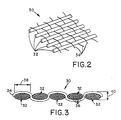
- Figs. 2 and 3 show a fabric 30 which is employed as the barrier ply 12 and comprises warp yarns 32 and weft yarns 34 which extend substantially perpendicular to the warp yarns and are interwoven therewith.
- Weft yarns 34 generally do not act as reinforcing elements of the fabric but are used to control the spacing of the warp yarns and thereby the packing density of the warp yarns in the fabric.
- the weft yarns 32 have an elongation at break of at least 150%, and in a barrier ply the fabric has forty to one hundred and twenty, most preferably sixty to eighty, weft yarns per meter as measured parallel to said warp yarns.
- Fabric 30 used in the practice of the invention can be manufactured on conventional weaving equipment.
- the warp yarns 32 of the present invention comprise at least two side-by-side filaments 36 which are not twisted together, i.e., the yarns consist of a bundle of parallel filaments having zero yarn twist.
- Each warp yarn consists of a plurality of filaments 36 (which is understood to mean two or more filaments) of at least one material selected from the group consisting of aliphatic or aromatic polyamides, polyesters and rayons.
- Each warp yarn in the barrier ply has a denier in the range of four hundred to three thousand. As used herein "denier” is understood to mean the weight in grams of nine thousand meters of a yarn.
- each warp yarn comprises at least one hundred nylon (aliphatic polyamide) filaments and the warp yarns each have a denier in the range of seven hundred fifty to one thousand.
- the terms "consists of” and “consisting of” are understood to limit a warp yarn to only the side-by-side filaments and precludes any other component, such as a filament spirally wrapped around the side-by-side filaments.
- Fig. 3 illustrates that the noncircular cross-sectional shape of the warp yarns 32 allows a particularly dense packing of the filaments.
- Such yarns 32 can be manufactured by the well known processes of heat drawing, followed by dipping, or the process can be reversed by first dipping and then heat drawing the polymeric material.
- the coating, drawing and heat treating process may be adjusted to give the yarns of the fabric the physical properties such as strength, shrinkage, elongation, modulus, etc. desired by a tire engineer for a particular tire.
- these warp yarns 32 having no yarn twist are capable of absorbing in a conventional dipping process a high amount of coating solution. Since the multi-filament yarns without twist can be fully impregnated, they can be advantageously used in pneumatic tires.
- the warp yarns of the fabric of the present invention can absorb more than 10% of their weight in adhesive solution as the following example will show.
- Fabric used as a barrier ply in the practice of the invention comprised on an 840 denier multi-filament yarn of Nylon 6,6 (comprising 140 filaments) woven with olboplastTM 25 weft cords into a fabric having 22 ends per inch (EPI).
- a prior art barrier ply fabric comprises 840/1 denier multi-filament yarn of Nylon 6,6 with a twist of 472 turns per meter was woven into a ply having 36 EPI. Both woven fabrics were impregnated with the same adhesive solution, heat treated and drawn in a conventional dipping process. After the fabrics had been dried, samples of the individual warp yarns were separated from the fabric for analysis.
- the warp yarns have a reduced thickness as compared to the fabric of the prior art. It is well known in the art that a fabric of reduced thickness results in a tire component ply of lesser weight and in a ply that has a greater flexibility.
- Fig. 3 shows an enlarged view of a cross section of a fabric ply according to Fig. 2 wherein the warp yarns 32 of the fabric have a cross sectional shape which is substantially rectangular.
- the larger dimension (width) 38 of the cross section extends in the direction of the weft cords 34 and the smaller dimension (thickness) 40 of the cross section extends perpendicular thereto. It is preferred that the larger dimension be about 2 to 5 times the smaller dimension.
- each of the warp yarns 32 has a cross-sectional shape, taken perpendicular to the longitudinal axis of the yarn, with the greatest linear cross-sectional extent 38 of the cross-section being two to five times the linear cross-sectional extent 40 of the warp yarn as measured perpendicular to said greatest cross-sectional extent 38. It is preferred that in a tire 10 according to the invention the warp yarns 32 of the barrier ply 12 be disposed such that the greatest linear extent 38 of each warp yarn lies in a plane that is perpendicular to the axis of the rotation of the tire.
- the amount of protection against liner material infiltration of a carcass ply that the fabric can provide as a barrier ply is a function of the packing density of the warp yarns, i.e., the relative width of the warp yarns, and their relative spacing.
Abstract
A tubeless tire (10) has a barrier ply (12) interposed between a liner (14) and a carcass ply (16) to restrict intrusion of the liner material into the spaces between the cables of the carcass ply (16). The barrier ply (12) has warp yarns (32) of side-by-side filaments (36) and the warp yarns have a yarn twist of zero. Each of the warp yarns (32) has a cross sectional shape such that the greatest linear dimension (38) of the cross-section is two to five times the linear cross-sectional extent (40) of the warp yarn as measured perpendicular to said greatest cross-sectional extent (38).
Description
- The present invention relates to the employment of a barrier ply in a tubeless pneumatic tire.
- The liner of a pneumatic tire is a layer of low permeability elastomeric material positioned inside the tire to minimize air loss. Butyl rubber and other materials typically used as liners have exhibited the characteristic of extruding into regions between the parallel cords or cables of the adjacent carcass reinforcement ply, particularly in radial ply tires. A known method for preventing the intrusion of the liner material into the spaces between the parallel cords or cables of a carcass ply is to add to the tire a "barrier" ply disposed between the liner and carcass ply. A separate reinforcement material can be utilized for this purpose, as is illustrated in U.S. Patent 3,165,138.
- It is known from EPO Published Application 172,294 that a barrier ply may comprise a plurality of cords or cables with a greater density of cords per inch (2.54 cm) of width than in the carcass ply. Although there is some latitude for varying the cord density in a barrier ply, the cords may become spaced too far apart or too close together for adequate stress distribution or adhesion to the elastomer in which the cords are embedded. The barrier ply disclosed herein comprises a fabric having a lower end count, less thickness and lower weight than fabrics known to be presently in use in barrier plies.
- Exemplary embodiments of the invention are illustrated in the drawings which are a part of this specification, in which:
- Fig. 1 is a cross sectional view of a tire according to the invention;
- Fig. 2 illustrates a fabric used in the barrier ply of a tire according to the invention;
- Fig. 3 is a cross sectional view of the fabric of Fig. 2.
- With reference to Fig. 1, there is illustrated a
tire 10 having abarrier ply 12 which is interposed between a substantially gasimpermeable liner 14 and acarcass ply 16. Thebarrier ply 12 comprises fabric of the type disclosed in the following text, and has the warp yarns of the fabric oriented at 60° to 90° with respect to circumferential lines of the tire. "Circumferential" lines are circles disposed in planes that are perpendicular to the tire's axis of rotation and have centers that are located on said axis. - A tire according to the invention may further comprise a pair of
annular beads 18, abelt structure 20 and atread 22. Thecarcass ply 16 andbarrier ply 12 may be folded around the beads as illustrated at 24 and 26. - Figs. 2 and 3 show a
fabric 30 which is employed as thebarrier ply 12 and compriseswarp yarns 32 andweft yarns 34 which extend substantially perpendicular to the warp yarns and are interwoven therewith.Weft yarns 34 generally do not act as reinforcing elements of the fabric but are used to control the spacing of the warp yarns and thereby the packing density of the warp yarns in the fabric. Preferably, theweft yarns 32 have an elongation at break of at least 150%, and in a barrier ply the fabric has forty to one hundred and twenty, most preferably sixty to eighty, weft yarns per meter as measured parallel to said warp yarns.Fabric 30 used in the practice of the invention can be manufactured on conventional weaving equipment. - The
warp yarns 32 of the present invention comprise at least two side-by-side filaments 36 which are not twisted together, i.e., the yarns consist of a bundle of parallel filaments having zero yarn twist. Each warp yarn consists of a plurality of filaments 36 (which is understood to mean two or more filaments) of at least one material selected from the group consisting of aliphatic or aromatic polyamides, polyesters and rayons. Each warp yarn in the barrier ply has a denier in the range of four hundred to three thousand. As used herein "denier" is understood to mean the weight in grams of nine thousand meters of a yarn. Preferably, each warp yarn comprises at least one hundred nylon (aliphatic polyamide) filaments and the warp yarns each have a denier in the range of seven hundred fifty to one thousand. As used herein and in the claims the terms "consists of" and "consisting of" are understood to limit a warp yarn to only the side-by-side filaments and precludes any other component, such as a filament spirally wrapped around the side-by-side filaments. - Fig. 3 illustrates that the noncircular cross-sectional shape of the
warp yarns 32 allows a particularly dense packing of the filaments. The volume of the interstices between thenoncircular warp yarns 32, as compared to the prior art circular cross section yarns, having been considerably reduced.Such yarns 32 can be manufactured by the well known processes of heat drawing, followed by dipping, or the process can be reversed by first dipping and then heat drawing the polymeric material. The coating, drawing and heat treating process may be adjusted to give the yarns of the fabric the physical properties such as strength, shrinkage, elongation, modulus, etc. desired by a tire engineer for a particular tire. It has been discovered that thesewarp yarns 32 having no yarn twist are capable of absorbing in a conventional dipping process a high amount of coating solution. Since the multi-filament yarns without twist can be fully impregnated, they can be advantageously used in pneumatic tires. - Analyses of the cross section of impregnated
warp yarns 32 have shown that the adhesive component is distributed throughout the yarn, filling up all interstices and thereby bonding loose filaments together to form a substantially uniform filament/rubber composite. - Whereas yarns or cords used in prior art barrier plies typically could absorb between 5% and 10% of their weight in coating solution, the warp yarns of the fabric of the present invention can absorb more than 10% of their weight in adhesive solution as the following example will show.
- Fabric used as a barrier ply in the practice of the invention comprised on an 840 denier multi-filament yarn of Nylon 6,6 (comprising 140 filaments) woven with olboplast™ 25 weft cords into a fabric having 22 ends per inch (EPI). A prior art barrier ply fabric comprises 840/1 denier multi-filament yarn of Nylon 6,6 with a twist of 472 turns per meter was woven into a ply having 36 EPI. Both woven fabrics were impregnated with the same adhesive solution, heat treated and drawn in a conventional dipping process. After the fabrics had been dried, samples of the individual warp yarns were separated from the fabric for analysis. The following table summarizes the test results:
TABLE I Fabric used in invention Fabric used in prior art Breaking strength: 82 Newtons 74 Newtons Ultimate elongation: 19% 21.5% Load at 1% elongation: 5.9 Newtons 3.52 Newtons 2% elongation: 9.3 Newtons 6.08 Newtons 3% elongation: 11.8 Newtons 8.00 Newtons 4% elongation: 15.3 Newtons 9.89 Newtons 7% elongation: 24.8 Newtons 17.17 Newtons 14% elongation: 67.6 Newtons 46.96 Newtons - In a preferred embodiment of the invention, the warp yarns have a reduced thickness as compared to the fabric of the prior art. It is well known in the art that a fabric of reduced thickness results in a tire component ply of lesser weight and in a ply that has a greater flexibility.
- Fig. 3 shows an enlarged view of a cross section of a fabric ply according to Fig. 2 wherein the
warp yarns 32 of the fabric have a cross sectional shape which is substantially rectangular. The larger dimension (width) 38 of the cross section extends in the direction of theweft cords 34 and the smaller dimension (thickness) 40 of the cross section extends perpendicular thereto. It is preferred that the larger dimension be about 2 to 5 times the smaller dimension. Put another way, each of thewarp yarns 32 has a cross-sectional shape, taken perpendicular to the longitudinal axis of the yarn, with the greatestlinear cross-sectional extent 38 of the cross-section being two to five times thelinear cross-sectional extent 40 of the warp yarn as measured perpendicular to saidgreatest cross-sectional extent 38. It is preferred that in atire 10 according to the invention thewarp yarns 32 of thebarrier ply 12 be disposed such that the greatestlinear extent 38 of each warp yarn lies in a plane that is perpendicular to the axis of the rotation of the tire. - In the example referred to above, the following dimensions were measured on the impregnated yarns:
thickness (40): 0.30 ± 0.05 mm
width (38): 0.90 ± 0.10 mm - This represents a substantial reduction in thickness over the prior art yarns which have a thickness of at least 0.4 mm.
- The amount of protection against liner material infiltration of a carcass ply that the fabric can provide as a barrier ply is a function of the packing density of the warp yarns, i.e., the relative width of the warp yarns, and their relative spacing.
- While certain representative embodiments have been shown for the purpose of illustrating the invention, it will be apparent to those skilled in the art that various changes and modifications may be made therein without departing from the spirit or scope of the invention.
Claims (5)
1. A tire (10) comprising a barrier ply (12) which is disposed between a substantially air impermeable liner (14) and a carcass ply (16), said barrier ply (12) comprising a plurality of warp yarns (32) extending parallel to one another and oriented at 60° to 90° with respect to circumferential lines of the tire, a plurality of weft yarns (34) extending substantially perpendicular to said warp yarns and interwoven therewith, characterized by each warp yarn (32) having a yarn twist of zero and consisting of at least two side-by-side filaments (36), said filaments each comprising at least one material selected from the group consisting of aliphatic or aromatic polyamides, polyesters and rayons, said weft yarns (34) having an elongation of at least 150% at break, each of said warp yarns (32) having a cross sectional shape taken perpendicular to the longitudinal axis of the yarn with the greatest linear cross-sectional extent (38) of said cross-section being 2 to 5 times the linear cross-sectional extent (40) of the warp yarn as measured perpendicular to said greatest cross-sectional extent.
2. A tire (10) according to claim 1 characterized by each of said warp yarns (32) having a greatest linear cross-sectional extent (38) of about .9 mm, and the average cross-sectional extent (40) as measured perpendicular to said greatest cross-sectional extent being about .3 mm.
3. A tire (10) as claimed in any of the preceding claims characterized by each warp yarn (32) of said barrier ply (12) having a denier of 400 to 3,000.
4. A tire (10) as claimed in any of the preceding claims characterized by each warp yarn (32) of said barrier ply (12) comprising at least 100 nylon filaments (36), each warp yarn having a denier of 750 to 1,000, and there being 18 to 26 warp yarns per 2.54 cm as measured perpendicular to said warp yarns.
5. A tire (10) as claimed in any of the preceding claims characterized by said barrier ply (12) having 40 to 120 weft yarns (34) per meter as measured parallel to said warp yarns (32).
Applications Claiming Priority (2)
| Application Number | Priority Date | Filing Date | Title |
|---|---|---|---|
| US25834788A | 1988-10-17 | 1988-10-17 | |
| US258347 | 1988-10-17 |
Publications (2)
| Publication Number | Publication Date |
|---|---|
| EP0365465A2 true EP0365465A2 (en) | 1990-04-25 |
| EP0365465A3 EP0365465A3 (en) | 1991-05-15 |
Family
ID=22980175
Family Applications (1)
| Application Number | Title | Priority Date | Filing Date |
|---|---|---|---|
| EP19890630189 Withdrawn EP0365465A3 (en) | 1988-10-17 | 1989-10-10 | Tubeless tire containing a barrier ply |
Country Status (2)
| Country | Link |
|---|---|
| EP (1) | EP0365465A3 (en) |
| JP (1) | JPH0254604U (en) |
Cited By (1)
| Publication number | Priority date | Publication date | Assignee | Title |
|---|---|---|---|---|
| EP0576861A1 (en) * | 1992-06-29 | 1994-01-05 | Bridgestone/Firestone, Inc. | Tire fabric with polyester/high wet modulus rayon filling |
Citations (3)
| Publication number | Priority date | Publication date | Assignee | Title |
|---|---|---|---|---|
| DE463035C (en) * | 1925-12-17 | 1928-07-23 | Overseas Wire Cord Company | Barrel jacket with metal wire inserts |
| FR2242496A1 (en) * | 1973-08-29 | 1975-03-28 | Bekaert Sa Nv | |
| FR2536017A1 (en) * | 1982-11-16 | 1984-05-18 | Uniroyal Englebert Gmbh | Vehicle tyre without an air chamber comprising especially an internal protective layer and a bead protection layer |
Family Cites Families (2)
| Publication number | Priority date | Publication date | Assignee | Title |
|---|---|---|---|---|
| JPS5632325U (en) * | 1979-08-20 | 1981-03-30 | ||
| DE3475054D1 (en) * | 1984-08-21 | 1988-12-15 | Goodyear Tire & Rubber | Pneumatic tire |
-
1989
- 1989-10-10 EP EP19890630189 patent/EP0365465A3/en not_active Withdrawn
- 1989-10-16 JP JP11978689U patent/JPH0254604U/ja active Pending
Patent Citations (3)
| Publication number | Priority date | Publication date | Assignee | Title |
|---|---|---|---|---|
| DE463035C (en) * | 1925-12-17 | 1928-07-23 | Overseas Wire Cord Company | Barrel jacket with metal wire inserts |
| FR2242496A1 (en) * | 1973-08-29 | 1975-03-28 | Bekaert Sa Nv | |
| FR2536017A1 (en) * | 1982-11-16 | 1984-05-18 | Uniroyal Englebert Gmbh | Vehicle tyre without an air chamber comprising especially an internal protective layer and a bead protection layer |
Cited By (1)
| Publication number | Priority date | Publication date | Assignee | Title |
|---|---|---|---|---|
| EP0576861A1 (en) * | 1992-06-29 | 1994-01-05 | Bridgestone/Firestone, Inc. | Tire fabric with polyester/high wet modulus rayon filling |
Also Published As
| Publication number | Publication date |
|---|---|
| JPH0254604U (en) | 1990-04-20 |
| EP0365465A3 (en) | 1991-05-15 |
Similar Documents
| Publication | Publication Date | Title |
|---|---|---|
| US4724881A (en) | Pneumatic vehicle tire | |
| EP0296093B1 (en) | Pneumatic tires | |
| EP1431076B1 (en) | Pneumatic tire having an overlay reinforcement | |
| US4073330A (en) | Tire cord fabrics for belts of belted pneumatic tires | |
| EP2045379B1 (en) | Pneumatic aircraft tire | |
| US5221382A (en) | Pneumatic tire including gas absorbing cords | |
| US4284117A (en) | Steel belted radial ply tires with cap plies employing single yarn reinforcing elements | |
| US6026879A (en) | Pneumatic tire with polyester belt cord | |
| EP0624667A2 (en) | Composite material ply and process for making it | |
| KR19990037011A (en) | A reinforcing fabric for elastic material products and an elastic material product comprising the reinforcing fabric | |
| EP0329594A2 (en) | Pneumatic tires | |
| BRPI0804649A2 (en) | highly extensively cut resistant barrier | |
| US20020074068A1 (en) | Tire anti-puncture product | |
| US6685785B1 (en) | Synchronous drive belt with scaffold stretch fabric | |
| EP0447807B1 (en) | Fiber reinforced rubber | |
| EP1547817A2 (en) | Pneumatic tire with blended composite fiber cords | |
| US5036896A (en) | Pneumatic tire with oriented carcass plies, the plies having aramid filaments | |
| EP0365465A2 (en) | Tubeless tire containing a barrier ply | |
| EP0329592A2 (en) | A pneumatic tire | |
| US20050245340A1 (en) | Power transmission belt and method of making same | |
| EP3619052B1 (en) | Reinforcement strip for a cap ply of a pneumatic tire | |
| EP0705209B1 (en) | Rubberline belting | |
| CA2257781C (en) | A metallic cord for the reinforcement of elastomers | |
| EP0443459B1 (en) | Fiber reinforced rubber | |
| EP4008816A1 (en) | Fabric structure for a tire |
Legal Events
| Date | Code | Title | Description |
|---|---|---|---|
| PUAI | Public reference made under article 153(3) epc to a published international application that has entered the european phase |
Free format text: ORIGINAL CODE: 0009012 |
|
| 17P | Request for examination filed |
Effective date: 19891020 |
|
| AK | Designated contracting states |
Kind code of ref document: A2 Designated state(s): DE ES FR GB |
|
| PUAL | Search report despatched |
Free format text: ORIGINAL CODE: 0009013 |
|
| AK | Designated contracting states |
Kind code of ref document: A3 Designated state(s): DE ES FR GB |
|
| STAA | Information on the status of an ep patent application or granted ep patent |
Free format text: STATUS: THE APPLICATION HAS BEEN WITHDRAWN |
|
| 18W | Application withdrawn |
Withdrawal date: 19920115 |