EP0365035B1 - Cassette loading device for image forming apparatus - Google Patents
Cassette loading device for image forming apparatus Download PDFInfo
- Publication number
- EP0365035B1 EP0365035B1 EP89119529A EP89119529A EP0365035B1 EP 0365035 B1 EP0365035 B1 EP 0365035B1 EP 89119529 A EP89119529 A EP 89119529A EP 89119529 A EP89119529 A EP 89119529A EP 0365035 B1 EP0365035 B1 EP 0365035B1
- Authority
- EP
- European Patent Office
- Prior art keywords
- cassette
- loading device
- sheet
- pins
- chains
- Prior art date
- Legal status (The legal status is an assumption and is not a legal conclusion. Google has not performed a legal analysis and makes no representation as to the accuracy of the status listed.)
- Expired - Lifetime
Links
Images


Classifications
-
- B—PERFORMING OPERATIONS; TRANSPORTING
- B65—CONVEYING; PACKING; STORING; HANDLING THIN OR FILAMENTARY MATERIAL
- B65H—HANDLING THIN OR FILAMENTARY MATERIAL, e.g. SHEETS, WEBS, CABLES
- B65H1/00—Supports or magazines for piles from which articles are to be separated
- B65H1/26—Supports or magazines for piles from which articles are to be separated with auxiliary supports to facilitate introduction or renewal of the pile
- B65H1/266—Support fully or partially removable from the handling machine, e.g. cassette, drawer
-
- B—PERFORMING OPERATIONS; TRANSPORTING
- B65—CONVEYING; PACKING; STORING; HANDLING THIN OR FILAMENTARY MATERIAL
- B65H—HANDLING THIN OR FILAMENTARY MATERIAL, e.g. SHEETS, WEBS, CABLES
- B65H1/00—Supports or magazines for piles from which articles are to be separated
- B65H1/04—Supports or magazines for piles from which articles are to be separated adapted to support articles substantially horizontally, e.g. for separation from top of pile
-
- G—PHYSICS
- G03—PHOTOGRAPHY; CINEMATOGRAPHY; ANALOGOUS TECHNIQUES USING WAVES OTHER THAN OPTICAL WAVES; ELECTROGRAPHY; HOLOGRAPHY
- G03G—ELECTROGRAPHY; ELECTROPHOTOGRAPHY; MAGNETOGRAPHY
- G03G15/00—Apparatus for electrographic processes using a charge pattern
- G03G15/65—Apparatus which relate to the handling of copy material
- G03G15/6502—Supplying of sheet copy material; Cassettes therefor
-
- B—PERFORMING OPERATIONS; TRANSPORTING
- B65—CONVEYING; PACKING; STORING; HANDLING THIN OR FILAMENTARY MATERIAL
- B65H—HANDLING THIN OR FILAMENTARY MATERIAL, e.g. SHEETS, WEBS, CABLES
- B65H2801/00—Application field
- B65H2801/03—Image reproduction devices
- B65H2801/06—Office-type machines, e.g. photocopiers
-
- B—PERFORMING OPERATIONS; TRANSPORTING
- B65—CONVEYING; PACKING; STORING; HANDLING THIN OR FILAMENTARY MATERIAL
- B65H—HANDLING THIN OR FILAMENTARY MATERIAL, e.g. SHEETS, WEBS, CABLES
- B65H2801/00—Application field
- B65H2801/03—Image reproduction devices
- B65H2801/21—Industrial-size printers, e.g. rotary printing press
Definitions
- the present invention relates to a cassette loading device for an image forming apparatus, and more particularly, it relates to an automatic cassette loading device which is arranged in a sheet feeding portion of an image forming apparatus such as a copying machine, printing machine, laser printer and the like which can automatically load or unload a "cassette” accommodating number of sheets with respect to the image forming apparatus.
- an image forming apparatus such as a copying machine, printing machine, laser printer and the like which can automatically load or unload a "cassette” accommodating number of sheets with respect to the image forming apparatus.
- the wording "cassette” is used as a general term for indicating all of sheet accommodating means to be available, and, therefore, in the present invention, the sheet accommodating means is not limited to the so-called removable box-shaped cassette.
- first type is a side loading type wherein the cassette is retracted in a direction opposite to a sheet feeding direction
- second type is a front loading type wherein the cassette is retracted in a direction perpendicular to the sheet feeding direction.
- the cassette is slidably supported by guide rails and the like.
- the copying machines of the front loading type have been increased for the reasons that (1) less installation space required, (2) the sheet can be replenished without unloading the cassette, (3) the cassette can easily be handled at a front side, and the like.
- JP-A-60 148 842 For further description of the prior art see JP-A-60 148 842.
- An object of the present invention is to provide an image forming apparatus which can solve the above-mentioned conventional problems by permitting or allowing the engagement and disengagement between a sheet accommodating means and a shifting means.
- the present invention as defined in claim 1 provides an image forming apparatus which is provided with a sheet accommodating means accommodating a number of sheets therein and removably mounted on the apparatus, and which is characterized by that a shifting means for shifting the sheet accommodating means from an insertion position to a sheet feeding position, and an engagement means for detachably connecting the sheet accommodating means to the shifting means.
- the sheet accommodating means can be removably connected to the shifting means through the engagement means, the image forming apparatus can be simplified and the positioning of the sheet accommodating means can be easily performed. Further, the loading and unloading of the sheet accommodating means can also be performed easily.
- the time duration for shifting the sheet accommodating means can be properly controlled, thus saving the unnecessary long time for shifting the sheet accommodating means.
- the sheets having the size other than the maximum size are replenished, the sheets can be supplied to the sheet accommodating means at a stable position.
- first and second shifting means so that, when the sheet accommodating means is unloaded from the image forming apparatus, the sheet accommodating means is shifted by an electric force through the medium of the first shifting means and then is shifted, by an elastic force through the medium of the second shifting means, to a position where the sheet accommodating means are separated from a detecting means, it is possible to automatically separate the sheet accommodating means from the detecting means automatically, thus being labor-saving for manualy separating or disengaging the sheet accommodating means from the detecting means.
- the detecting means detects the increase in load in the driving means, the sheet accommodating means is stopped or reversed to move in an opposite direction, the time necessary to detect the load variation of the driving means can be reduced, thus preventing the damage of the sheet accommodating means and/or image forming apparatus.
- the engagement means (member) is stopped at a down-stream side (with respect to the shifting direction of the sheet accommodating means) of an arcuate portion of a belt wrapped around a roller of a belt-roller assembly, the roller can be prevented from being rotated, thus avoiding the aberration in the position where the sheet accommodating means is stopped.
- the sheet accommodating means can automatically be ejected or returned to the insertion position by the shifting means, a ejection key is not necessarily provided and the sheet accommodating means is prevented from being ejected inadvertently.
- the feed rollers 6 are positioned in the vicinity of the shifting device 5.
- a photosensitive drum 7 supported by a shaft 7a is arranged within the machine frame 2, which drum can bear a toner image thereon.
- the shifting device 5 comprises frames 9 and 10, one of which (i.e., frame 9) includes a reversible motor 11 arranged therein.
- the motor 11 has a motor shaft 11a on which a gear 12 is fixed, which gear 12 is meshed with a gear 15 fixed to a shaft 13 rotatably supported by the frame 9.
- a sprocket 16 On the other end of the shaft 13 a sprocket 16 is fixed, which sprocket is operatively connected, through a chain 20, to a sprocket 19 fixed to a shaft 17 rotatably supported by the frame 9. Further, a shield plate 21 is arranged on links L of the chain 20, which shield plate 21 is adapted to turn ON and OFF (i.e., activate and deactivate) sensors 22 and 23 arranged in the vicinity of the chain 20.
- the frames 9, 10 have rail portions 9a, 10a, respectively, on which guide rollers 25 and a cassette detecting sensor 26 are arranged.
- the motor shaft 11a of the motor 11 extends into the frame 10.
- a gear 27 is fixed on the free end of the shaft 11a .
- the gear 27 is meshed with a gear 30 fixed to a shaft 29 rotatably supported by the frame 10.
- a sprocket 31 is fixed, which sprocket is operatively connected, through a chain 35, to a sprocket 33 fixed to a shaft 32 rotatably supported by the frame 10.
- the chains 35 and 20 have pins 36 (Fig. 3) which can be moved together with the chains in response to the rotation of the chains 35, 20. Further, the cassette 3 is provided at its both front sides with L-shaped recesses 37 adapted to receive the pins 36 of the chains.
- the reference symbol G designates an original (or manuscript) cover pivotable around a hinge H in a direction B.
- the copying machine 1 includes a controlling portion C, to an input portion of which the sensors 22, 23, cassette detecting sensor 26 and a cassette taking-out button 40 are connected; whereas the motor 11 is connected to an output portion of the controlling portion C.
- the pins 36 of the chains are positioned in a position where the pins face to entrance openings 37c (Fig. 4) of the corresponding L-shaped recesses 37, i.e., a position where the shield plate 21 is detected by the sensor 22 (refer to Fig. 1). Accordingly, when the cassette 3 is inserted into the machine frame along the rail portions 9a, 10a, the pins 36 are introduced into the corresponding L-shaped recesses 37.
- the pins 36 are aligned with the corresponding entrance openings 37a of the L-shaped recesses, and then, when cassette 3 is shifted until straight portions 37e of the recesses 37 have passed through the corresponding pins 36, the cassette detecting sensor 26 is turned ON by the bottom surface of the cassette 3.
- the controlling portion C receives an ON signal from the sensor 26, thereby driving the motor 11.
- the driving force from the motor 11 is transmitted to the sprocket 16 through the gears 12, 15 and to the sprocket 31 through the motor shaft 11a and gears 27, 30.
- the chain 20 is rotated or turned in a clockwise direction through the rotation of the sprocket 16 and the chain 35 is turned through the rotation of the sprocket 31.
- the pins 36 are firstly moved along arcuate paths to abut against corresponding vertical surfaces 37a of the L-shaped recesses 37, and, thereafter, the pins 36 are shifted along straight paths in reponse to further rotation of the chains 20, 35, thus shifting the cassette 3 inwardly of the machine frame (in a direction D) as shown in Fig. 3. Accordingly, the cassette 3 is automatically inserted after it activates the cassette detecting sensor 26. Further, when the cassette 3 is inserted until the shield plate 21 turns the sensor 23 OFF, the controlling portion C receives an OFF signal from the sensor 23, thereby stopping the motor 11.
- the taking-out button 40 is activated or turned ON. Consequently, the braking means or locking means is deactivated or released, and, at the same time, the controlling portion C receives an ON signal from the taking-out button 40, thus rotating the motor 11 in a reverse direction to rotate the sprockets 16, 31 in a direction F (Fig. 5).
- the pins 36 of the chains abut against the other vertical surfaces 37b (opposed to the above-mentioned vertical surfaces 37a) of the L-shaped recesses 37 to return the cassette 3 in the direction F. Thereafter, when the pins 36 is moved upwardly along the arcuate paths, the returning movement of the cassette 3 is stopped.
- the controlling portion C receives an OFF signal from the sensor 22, thereby deactivating the motor 11 to stop the rotation of the chains 20, 35.
- the braking means or locking means may be activated again to maintain the chains in the stopped condition.
- the cassette 3 can be removed from the machine frame 2 by pulling the cassette rightwardly.
- the cassette 3 can be a pawl separating system as well as another type separating system.
- the controlling portion judges whether the cassette detecting sensor 26 is turned ON or not (in a step S1); if yes, the controlling portion then judges whether the sensor 23 is turned ON or not (in a step S2). If it is judged that the sensor 23 is turned ON, the controlling portion then judges whether a copy start key (not shown) is turned ON or not (in a step S3); if yes, a sheet feed motor (not shown) is activated or turned ON (in a step S4).
- the activation of the sheet feed motor causes the feed rollers 6 to rotate, thereby feeding the sheet S from the cassette 3.
- the toner image formed on the photosensitive drum 7 is transferred onto the sheet S, and then the image transferred on the sheet is fused or fixed to the sheet by means of a fixing device (not shown). Thereafter, the sheet is ejected from the machine frame 2.
- the controlling portion judges whether the sheet feeding is finished or not (in a step S5); if yes, the controlling portion turns the sheet feeding motor OFF, thereby stopping the sheet feeding operation (in a step S6). Further, the controlling portion judges whether a cassette taking-out key (not shown) is activated (turned ON) or not (in a step S7); if not, the controlling portion waits until the copy start key is turned ON.
- the controlling portion drives the pulse motor 11 in the positive or normal direction to introduce the cassette 3 into the machine frame (in a step S8).
- the drive force from the motor 11 is transmitted to the sprocket 16 through the gears 12, 15 and is also transmitted to the sprocket 31 through the motor shaft 11a and the gears 27, 30.
- the rotation of the sprockets 16, 31 causes the chains 20, 35 to rotate, with the result that the pins 36 provided on the chains abut against the vertical surfaces 37a of the corresponding L-shaped recesses 37 formed in the cassette, thereby shifting the cassette 3 toward the interior of the machine frame in response to the rotational movement of the chains 20, 35.
- the controlling portion judges whether the sensor 23 is turned ON or not (in a step S9); if yes, the pulse motor 11 is turned OFF (in a step S10). In this way, the cassette 3 is reached to the predetermined position in the machine frame 2 by means of the shifting device 5. Thereafter, the controlling portion executes the sequence from the above step S3 on.
- step S9 if it is judged that the sensor 23 is not turned ON, the controlling portion judges whether the cassette taking-out key is turned ON or not (in a step S11); if not, the controlling portion then executes the sequence from the above step S9 on.
- the controlling portion rotates the pulse motor 11 in the reverse direction to shift the cassette 3 toward the outlet (in a step S12).
- the driving force from the pulse motor 11 is transmitted to the sprockets 16, 31 in the same manner as mentioned above, thus rotating the chains 20, 35 in the anticlockwise direction (Fig. 4) through the rotation of the sprockets. Consequently, the pins 36 of the chains abut against the vertical surfaces 37b of the corresponding L-shaped recesses 37, thus shifting the cassette 3 toward the outlet.
- the controlling portion judges whether the sensor 22 is turned ON or not (in a step S13); if yes, the pulse motor 11 is turned OFF (in a step S14).
- the controlling portion judges whether the cassette detecting sensor 26 is tuned ON or not (in a step S15); if not, the sequence from the above step S1 is repeated.
- step S7 if it is judged that the cassette taking-out key is turned ON, the sequence from the above step S12 is executed.
- the cassette 3 used with the copying machine has a sheet size detecting block 39 removably mounted on a front surface (a forward surface with respect to the cassette inserting direction A) of the cassette.
- the block 39 serves to push one of sheet size detecting switches 40a, 40b, 40c arranged on the machine frame 2. Further, the block 39 can be changed to other block in accordance with the size of the sheets to be accommodated in the cassette.
- an attachment plate 41 is provided on a portion of the machine frame 2 opposed to the block 39, which attachment plate 41 is slidably supported by pins each having an enlarged free end and protruded from a bracket 42 fixed to the machine frame 2.
- a compression spring 45 is arranged around each pin 43 between the enlarged end thereof and the attachment plate 41.
- the above-mentioned sheet size detecting switches 40a, 40b, 40c and a cassette existence detecting switch 40d are arranged on the attachment plate 41.
- the cassette 3 has positioning spacers 46 for maintaining a predetermined distance between the attachment plate 41 and the cassette 3 itself, these spacers being situated outside of the switch group 40a - 40d.
- the copying machine includes a controlling portion 47 having an input portion connected to the sheet size detecting switch 40a, 40b, 40c, cassette existence detecting switch 40d, sensor 22 and cassette detecting sensor 26, and an output portion connected to the pulse motor 11.
- the controlling portion 47 In a condition that the cassette 3 is loaded on the copying machine, signals from the sheet size detecting switches 40a, 40b, 40c, cassette existence detecting switch 40d, sensor 22 and cassette detecting sensor 26 are being sent to the controlling portion 47. Accordingly, on the basis of these signals, the controlling portion confirms the face that the cassette exists within the machine and is positioned in the predetermined position and detects the sheet size (in a step S1).
- the controlling portin 47 receives an ON signal from the taking-out switch and determines the number of pulses corresponding to the sheet size (in a step S3), thereby actuating the pulse motor 11 by such number of pulses (in a step S4). Consequently, the sprockets 16, 31 are rotated in the direction E (refer to Fig. 3) to abut the pins 36 of the chains against the vertical surfaces 37b of the corresponding L-shaped recesses 37 formed in the cassette, thus shifting the cassette 3 toward the outlet (in the direction F in Fig. 3). After the pulse motor 11 is rotated by the predetermined pulses, the pulse motor 11 is stopped. In this point, the cassette 3 is retracted or protruded from the machine frame 2 by a distance corresponding to the sheet size. In this way, the taking-out of the cassette is finished (in a step S5).
- the pins 36 of the chains are aligned with the entrance openings 37c of the corresponding recesses 37, the pins 36 can be introduced into the corresponding recesses 37 by inserting the cassette 3 along the rail portions 9a, 10a.
- the controlling portion receives the ON signal from the cassette detecting sensor 26, thereby actuating the pulse motor 11.
- the driving force from the pulse motor 11 is transmitted to the sprocket 16 through the gears 12, 15 and is also transmitted to the sprocket 31 through the motor shaft 11a and the gears 27, 30.
- the rotation of the sprockets 16, 31 causes the chains 20, 35 to rotate, with the result that the pins 36 of the chains abut against the vertical surfaces 37a of the corresponding recesses 37 formed in the cassette, thereby shifting the cassette 3 toward the interior of the machine frame (in the direction D) (refer to Fig. 3) in response to the rotational movement of the chains 20, 35.
- the controlling portion 47 receives the OFF signal from the sensor 22, thereby stopping the pulse motor 11. In this way, the cassette 3 is positioned in the predetermined position.
- cassettes 3a, 3b, 3c may be prepared for sheets having different sizes.
- These cassettes 3a, 3b, 3c have L-shaped recesses 37 formed therein at different positions, respectively.
- the cassette 3a is used for receiving the sheets having large size
- the cassette 3b is used for receiving the sheets having intermediate size
- the cassette 3c is used for receiving the sheets having small size.
- the pulse motor 11 is stopped, thus completing the loading of the cassette.
- the first projection 3g is provided at a different position for each cassette 3a, 3b, 3c.
- the cassette 3c is unloaded from the machine frame, the cassette is shifted toward the outlet in the same manner as mentioned above.
- the pulse motor 11 is turned OFF. In this way, the cassette 3c is retracted up to a position where the sheets having the small size (l1 in Fig. 8) can easily be replenished.
- the copying machine includes an arm 139 rotatably supported by a machine frame 2a.
- An intermediate portion of the arm 139 is connected to one end of a bias spring 140, the other end of which is connected to the machine frame 2a.
- the arm 139 is normally held in a cocked or upright condition.
- a cassette detecting sensor 141 is arranged in the vicinity of a base end of the arm 139, which sensor 141 is adapted to be activated or deactivated (ON or OFF) by means of a projection 139a of the arm 139.
- a rotatable roller 142 is rotatably mounted on a free end of the arm 139.
- the pins 36 of the chains are aligned with the entrance openings 37c of the corresponding recesses 37, the pins 36 can be introduced into the corresponding recesses 37 by inserting the cassette 3 along the rail portions 9a, 10a (refer to Fig. 16A).
- the arm 139 is rotated in an anti-clockwise direction in opposition to the bias force of the spring 140 in response to the movement of the cassette (refer to Fig. 16B).
- the projection 139a of the arm 139 blocks an optical path between a light source and a light receiving portion of the cassette detecting sensor 141.
- the pulse motor 11 is rotated in the normal direction.
- the driving force from the motor 11 is transmitted to the chains 20, 35.
- the pins 36 are abutted against the vertical surfaces 37a of the corresponding recesses 37, thereby shifting the cassette 3 toward the interior of the machine frame (refer to Fig. 16C).
- the cassette 3 is shifted to the predetermined position and is positioned at that position in the same manner as previously mentioned.
- the cassette 3 is further shifted toward the outlet through the rotation of the arm 139 caused by the bias force of the spring 140, whereby the projection 139a of the arm 139 is retarded from the optical path between the light source and the light receiving portion of the cassette detecting sensor 141, thus turning the sensor 141 ON (refer to Fig. 17C).
- the copying machine becomes a waiting condition for receiving the cassette 3, in response to the ON signal from the sensor 141.
- the present invention is not limited to such example.
- a cassette detecting sensor 241′ which can be turned ON and OFF by means of the cassette 3 itself.
- the arm 239 connected to the bias spring 240 has no projection.
- a cassette shifting device 5 comprises frames 9 and 10, one of which (i.e., frame 9) includes a reversible motor 11 arranged therein.
- the motor 11 has a motor gear 11a on which a gear 12 is fixed, which gear 12 is meshed with a gear 15 fixed to a shaft 13 rotatably supported by the frame 9.
- a sprocket 16 is fixed to the other end of the shaft 13, which sprocket 16 is operatively connected, through a chain 20, to a sprocket 19 fixed to a shaft 17 rotatably supported by the frame 9.
- a shield plate 21 is arranged on the chain 20, which shield plate 21 is adapted to turn ON and OFF (i.e., activate and deactivate) sensors 22 and 23 arranged in the vicinity of the chain 20.
- the frame 9 has a rail portion 9a on which guide rollers 25 and a cassette detecting sensor 26 are arranged, whereas the frame 10 has a rail portion 10a on which guide rollers 25 are arranged.
- a slitted disc 357 is fixed to one end of the motor shaft 11a of the motor 11, and a photo-interrupter 356 is arranged in the vicinity of the disc 357.
- the other end of the motor shaft 11a extends into the frame 10 and has a gear 27 fixed thereto. Further, the gear 27 is meshed with a gear 30 fixed to a shaft 29 rotatably supported by the frame 10.
- a sprocket 33 is fixed on the other end of the shaft 29, which sprocket is operatively connected, through a chain 35, to a sprocket 33 fixed to a shaft 32 rotatably supported by the frame 10.
- the chains have pins 36 which can be moved together with the chains in response to the rotation of the chains 35, 20.
- the cassette 3 is provided at its both front sides with laid L-shaped recesses 37 adapted to receive the pins 36 of the chains.
- the copying machine 1 includes a controlling portion 355, to an input portion of which the sensors 22, 23, cassette detecting sensor 26 and the photo-interrupter 356 are connected; whereas the motor 11 is connected to an output portion of the controlling portion 355.
- the slitted disc 357 and the photo-interrupter 356 may be arranged at a position where these elements 356, 257 can sense the sprocket 19 or 16 which is subjected to a load initially when the abnormal condition occurs.
- the pins 36 of the chains are positioned in a position where the pins face to entrance openings 37c (Fig. 4) of the corresponding L-shaped recesses 37. Accordingly, when the cassette 3 is inserted into the machine frame along the rail portions 9a, 10a, the pins 36 are introduced into the corresponding L-shaped recesses 37. Then, when the bottom surface of the cassette 3 turns the cassette detecting sensor 26 ON, the controlling portion 355 receives an ON signal from the sensor 26, thereby driving the motor 11.
- the driving force from the motor 11 is transmitted to the sprocket 16 through the gears 12, 15 and is also transmitted to the sprocket 31 through the motor shaft 11a and gears 27, 30.
- the chain 20 is rotated or turned through the rotation of the sprocket 16 and the chain 35 is turned through the rotation of the sprocket 35.
- the pins 36 abut against corresponding vertical surfaces 37a of the L-shaped recesses 37, thus shifting the cassette 3 toward the interior of the machine frame in response to the rotational movement of the chains 20, 35.
- controlling portion 355 executes the sequence shown in a flow chart of Fig. 21.
- the controlling portion 355 judges, on the basis of a signal from the photo-interrupter, whether the motor is rotated at a predetermined speed, i.e., whether output pulses from the photo-interrupter 356 is regularly emitted at the predetermined timing (t) (refer to Fig. 22A) (in a step S1); if yes, the controlling portion judges whether there exists abnormal speed variation of the motor (in a step S2). If it is judged that the abnormal speed variation does not exist, the controlling portion 355 continues to shift the cassette 3. When the shield plate 21 turns the sensor 22 OFF, the motor 11 is stopped (in a step S3). In this way, the cassette 3 is positioned at a predetermined position.
- a start key (not shown) is depressed after an original or manuscript is laid on a platen (not shown)
- an image on the original is read by an optical system (not shown) comprising a lamp, mirrors and lenses, thus forming a latent image on a photosensitive drum in an image forming portion (not shown).
- An uppermost sheet S is separated from the sheet stack accommodated in the cassette 3 by a separating pawl (not shown), and the uppermost sheet is fed out from the cassette by a feed roller (not shown). Then, the sheet S is fed to a pair of regist rollers (not shown) by means of a pair of feeding rollers (not shown) until the sheet S reaches the nip between the regist rollers.
- the sheet After the sheet abuts against the nip between the regist rollers, the sheet is subjected to the feeding force due to the feeding rollers with slipping action, thus correcting the skew-feeding of the sheet. Then, the sheet S is further fed in synchronous with the movement of the image on the photosensitive drum by means of the regist rollers rotating at the predetermined timing. Then, the image (toner image) on the photosensitive drum is transferred onto the sheet S. Thereafter, the sheet is fed to a fixing or fusing device (not shown) by means of feeding belts (not shown), where the transferred image is fixed to the sheet.
- the sheet is ejected onto an ejector tray (not shown) by means of a pair of ejector rollers (not shown).
- a series of operations from the feeding of the sheet to the ejecting the sheet may be performed in a conventional manner.
- step S1 if it is judged that the motor is not rotated at the predetermined speed, i.e., if it is judged that any load is applied to the motor at the beginning to prevent the regular emission of the output pulses of the photo-interrupter 356 at the predetermined timing t (i.e., t ⁇ t′) (refer to Fig. 22B), the controlling portion 355 stops the motor 11 (in a step S4).
- step S2 if it is judged that there exists the abnormal speed variation due to irregularity of the duration between the output pulses, i.e., if the excessive load is applied to the shifting device during the insertion of the cassette, the controlling portion 355 stops the motor 11 and at the same time emits an warning signal E to indicate the abnormity to an operator. Accordingly, the operator can eliminate the abnormity by removing the cassette from the copying machine manually.
- the controlling portion 355 stops the motor 11 (or disengage any clutch between in the driving path to stop the chains without stopping the motor)
- the present invention is not limited to such example.
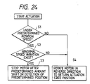
- the motor 11 may be stopped after it is rotated at a predetermined amount in the reverse direction.
- the motor may be rotated in the reverse direction to return the cassette 3 to the actuation start position.
- the cassette can be retarded from the abnormal condition and such abnormal condition can be warned, and such abnormal condition can be corrected quickly.
- the predetermined amount of reverse rotation of the motor can be performed by rotating the motor 11 in the reverse direction for a predetermined time through any timer circuit when any signal regarding the excessive load is emitted.
- the returning of the cassette to the actuation start position can be performed by returning the shield plate 21 to a position where it shields the sensor 22.
- the present invention is not limited to such example.
- a current detector for detecting a current value of the motor 11 may be used as the detecting means to detect the excessive load. In this case, when the current value exceeds a predetermined value, the controlling portion 355 confirms the fact that the excessive load occurs, thereby stopping the motor 11.
- the detection of the abnormal condition may be reset.
- the detection of the abnormal condition may be reset when the sensor 26 is turned OFF by withdrawing the cassette completely.
- a cassette shifting device 5a includes frames 9′ and 10′.
- the frame 9′ is constituted by a lower frame portion 9′b and an upper frame portion 9′c which can be slidably moved with respect to the lower frame portion 9′b in the directions A and B.
- the frame 10′ is constituted by a lower frame portion 10′b and an upper frame portion 10′c which can be slidably moved with respect to the lower frame portion 10′b in the directions A and B.
- the upper frame portion 10′c has a rack 455 arranged thereon, and a screw 456 meshed with the rack 455 is fixedly mounted on the lower frame portion 10′b.
- the upper frame portion 9′c and the lower frame portion 9′b of the frame 9′ have a rack and a screw, respectively, which are meshed with each other.
- the lower frame portion 9′b includes a rail portion 9′a having an inward upright end wall on which one end of a spring 457 is fixedly mounted.
- An abutment plate 459 is fixed to the other or free end of the spring 457, which abutment plate is adapted to abut against the cassette 3.
- the lower frame portion 10′b includes a similar rail portion 10′a having a similar abutment plate.
- the pins 36 are aligned with the corresponding entrance openings 37c of the L-shaped recesses 37, and then, when the cassette 3 is shifted until the straight portions 37d of the L-shaped recesses 37 have passed through the corresponding pins 36, the cassette detecting sensor 26 is turned ON by the bottom surface of the cassette 3 (refer to Fig. 25A). Consequently, the controlling portion receives an ON signal from the sensor 26, thereby actuating the motor 11.
- the driving force from the motor 11 is transmitted to the sprocket 16 through the gears 12, 15 and is also transmitted to the sprocket 31 through the motor shaft 11a and the gears 27, 30.
- the chain 20 is rotated in the clockwise direction through the rotation of the sprocket 16 and the chain 35 is also rotated through the rotation of the sprocket 31.
- the pins 36 are firstly moved along arcuate paths to abut against the corresponding vertical surfaces 37a of the L-shaped recesses 37, and, thereafter, the pins 36 are shifted along straight paths in response to further rotation of the chains 20, 35, thus shifting the cassette toward the interior of the machine frame (in the direction A) (refer to Fig. 25B). Accordingly, the cassette 3 is automatically shifted after it activates the cassette detecting sensor 26.
- the position of the cassette 3 with respect to the machine frame 2 can be finely adjusted by rotating the screws 456 to move the racks 455 thereby shifting the upper frame postions 9′c, 10′c of the frames 9′, 10′ with respect to the lower frame portions 9′b, 10′b in the direction A or B.
- the present invention is not limited to the use of such chains.
- V-shaped belts may be used in place of the chains.
- pulleys may be used in place of the sprockets 16, 19, 31 and 33.
- the shifting device 5 comprises frames 9 and 10, one of which (i.e., frame 9) includes a reversible motor 11 arranged therein.
- the motor 11 has a motor shaft 11a on which a gear 12 is fixed, which gear 12 is meshed with a gear 15 fixed to a shaft 13 rotatably supported by the frame 9.
- On the other end of the shaft 13 a sprocket 16 is fixed, which sprocket is operatively connected, through a chain 20, to a sprocket 19 fixed to a shaft 17 rotatably supported by the frame 9.
- a shield plate 21 is arranged on links L (refer to Fig. 2) of the chain 20, which shield plate 21 is adapted to turn ON or OFF (i.e., activate or deactivate) sensors 22 and 23 arranged in the vicinity of the chain 20.
- the frames 9, 10 have rail portions 9a, 10a, respectively, on which guide rollers 25 and a cassette detecting sensor 26 are arranged.
- the motor shaft 11a of the motor 11 extends into the frame 10.
- a gear 27 is fixed.
- the gear 27 is meshed with a gear 30 fixed to a shaft 29 rotatably supported by the frame 10.
- a sprocket 31 is fixed, which sprocket is operatively connected, through a chain 35, to a sprocket 33 fixed to a shaft 32 rotatably supported by the frame 10.
- the chains 35, 20 have opposed pins 36 (refer to Fig. 2) which can be moved together with the chains in response to the rotation of the chains 35, 20.
- the cassette 3 is provided at its both front sides with laid L-shaped recesses 37 adapted to receive the pins 36 of the chains.
- An abutment plate 555 against which the cassette can abut is fixed to inner ends of the frames 9 and 10.
- a cassette sensor 556 for detecting the fact that the cassette 3 reaches the sheet feeding position is arranged on the abutment plate 555.
- the reference numeral 62 designates a sheet separating pawl.
- a spring 557 one end of which is fixed to the vertical surface 37a is arranged in each L-shaped recess 37 of the cassette.
- the springs 557 serve to compensate discrepancy in positions of the pins 36.
- the copying machine 1 includes a controlling portion 559, to an input portion of which the sensors 22, 23, cassette detecting sensor 26 and a cassette sensor 556 are connected; whereas the motor 11 is connected to an output portion of the controlling portion 559.
- the sensor 23 acts as an outward home position sensor
- the sensor 22 acts as an inward home position sensor.
- ON or OFF signals from the sensors 26, 22, 23, 556 are sent to an microcomputer included in the controlling portion 559, and the controlling portion controls the normal or reverse rotation of the motor 11 properly on the basis of these signals.
- the pins 36 are positioned in a position where they face to the entrance openings 37c (Fig. 30) of the L-shaped recesses 37 of the cassette and is positioned on the chain portion wrapping around the sprocket 19 (Fig. 28). This position of the pins 36 is always ensured by stopping the motor 11 at a predetermined time after the shield plate 21 is detected by the home position sensor 23.
- each entrance opening 37c of the corresponding L-shaped recesses 37 of the cassette is formed in a position where, when the cassette 3 is situated on the rail portions 9a and 10a, the corresponding pin 36 can be smoothly inserted into the corresponding L-shaped recess 37. Accordingly, as the cassette 3 is inserted into the machine frame along the rail portions 9a, 10a, the pins 36 can be introduced into the corresponding recesses 37.
- the pins 36 are aligned with the corresponding entrance openings 37a of the L-shaped recesses, and then, when cassette 3 is shifted until straight portions 37d of the recesses 37 have passed through the corresponding pins 36, the cassette detecting sensor 26 is turned ON by the bottom surface of the cassette 3.
- the controlling portion 559 receives an ON signal from the sensor 26, thereby driving the motor 11.
- the driving force from the motor 11 is transmitted to the sprocket 16 through the gears 12, 15 and is also transmitted to the sprocket 31 through the motor shaft 11a and gears 27, 30.
- the chain 20 is rotated in a clockwise direction through the rotation of the sprocket 16 and the chain 35 is rotated through the rotation of the sprocket 35.
- the pins 36 are firstly moved along arcuate paths to abut against the corresponding springs 557 attached to the vertical surfaces 37a of the L-shaped recesses 37 (refer to Fig. 28), and, thereafter, the pins 36 are shifted along straight paths in response to further rotation of the chains 20, 35, thus shifting the cassette 3 inwardly of the machine frame (in a direction A) (refer to Fig. 6). Accordingly, the cassette 3 is automatically inserted after it activates the cassette detecting sensor 26.
- the cassette 3 is further shifted inwardly of the machine frame, the inward end wall of the cassette 3 abuts against the abutment plate 555 to turn the cassette sensor 556 ON (Fig. 32).
- the sensor 22 has not yet been turned OFF by the shield plate 21, and, therefore, the controlling portion 559 continues to rotate the motor 11.
- the shield plate 21 turns the sensor 22 OFF (Fig. 33)
- the controlling portion 559 receives an OFF signal from the sensor 22, thereby stopping the motor 11.
- the cassette is positioned in a predetermined position (Fig. 5).
- any braking means or locking means is provided in the motor or the gear train to maintain the cassette in the positioned condition.
- the operator slightly pulls the cassette outwardly (in the direction B) while further compressing the springs 557. Consequently, the inward end wall of the cassette 3 is separated to turn the cassette sensor 556 OFF. Then, the controlling portion 559 receives an OFF signal from the sensor 556, thereby deactivating the braking means or locking means, and at the same time, rotating the motor 11 in the reverse direction to rotate the sprockets 16, 31 in the direction E (Fig. 29).
- step S1 the cassette switch 556 is turned ON, sensor 23 is turned ON, sensor 22 is turned OFF, cassette detecting sensor is turned ON, and eject key is turned OFF, and motor 11 is turned OFF.
- the controlling portion judges whether the cassette detecting sensor 26 is turned from ON to OFF (in a step S2); if yes, the controlling portion actuates the motor in the reverse direction, i.e., in the feed out direction (in a step S3). Consequently, the cassette is shifted toward the outlet.
- the controlling portion in a step S4
- the motor is turned OFF (in a step S5) to finish the feed-out of the cassette (in a step S6).
- the braking means or locking means is activated again to hold the pins 36 in the stopped position. Since, in this point, the pins 36 are positioned in the straight portions 37d (Fig. 30) parallel to the entrance openings 37c and above the vertical surfaces 37a of the recesses 37, the cassette can easily be removed from the machine frame by pulling the cassette outwardly.
- the cassette sensor 556 can be utilized more effectively. Further, by constructing so that a timer is activated after a taking-out key is depressed, whereby the cassette taking-out movement is performed with a little delay, the operation of the taking-out key can be utilized together with the above operations.
- the present invention provides a cassette loading device for an image forming apparatus including a sheet feeding portion within which a cassette for accommodating sheets is loaded, and a sheet feeding means arranged in the sheet feeding portion and adapted to feed the sheet from the cassette loaded within the sheet feeding portion.
- the cassette loading device comprises a guide means for guiding the cassette to be loaded; a cassette shifting means rotatable along the guide means and having pins engageable with the cassette inserted into the sheet feeding portion; a driving means for driving the cassette shifting means; vertical surfaces formed in the cassette and against which the pins are abutted to shift the cassette; and horizontal recesses formed in the cassette and adapted to direct the pins toward the vertical surfaces.
- the present invention further provides an image forming apparatus which includes an image forming means for forming an image on the sheet being fed, and the above-mentioned cassette loading device.
Description
- The present invention relates to a cassette loading device for an image forming apparatus, and more particularly, it relates to an automatic cassette loading device which is arranged in a sheet feeding portion of an image forming apparatus such as a copying machine, printing machine, laser printer and the like which can automatically load or unload a "cassette" accommodating number of sheets with respect to the image forming apparatus. Here, the wording "cassette" is used as a general term for indicating all of sheet accommodating means to be available, and, therefore, in the present invention, the sheet accommodating means is not limited to the so-called removable box-shaped cassette.
- In the past, copying machines including removable cassettes therein have been known. Such conventional copying machines are generally grouped into two types: first type is a side loading type wherein the cassette is retracted in a direction opposite to a sheet feeding direction, and second type is a front loading type wherein the cassette is retracted in a direction perpendicular to the sheet feeding direction. In the copying machine of the front loading type, the cassette is slidably supported by guide rails and the like. Recently, the copying machines of the front loading type have been increased for the reasons that (1) less installation space required, (2) the sheet can be replenished without unloading the cassette, (3) the cassette can easily be handled at a front side, and the like.
- However, the above-mentioned conventional copying machine of the front loading type, there arose problems that the structure of the machine was complicated and it was difficult and troublesome to position the cassette with respect to the body of the copying machine, since a cassette support, the slidable guide rails and the like were used for slidably supporting and guiding the cassette.
- Particularly, in the copying machine of automatic loading type wherein the cassette is automatically loaded and unloaded, there arose problems that the positioning of the cassette was more complicated, that it was difficult to separate the cassette from a driving means, and that it was difficult to change the cassettes.
- For further description of the prior art see JP-A-60 148 842.
-
- An object of the present invention is to provide an image forming apparatus which can solve the above-mentioned conventional problems by permitting or allowing the engagement and disengagement between a sheet accommodating means and a shifting means.
- To achieve the above object, the present invention as defined in
claim 1 provides an image forming apparatus which is provided with a sheet accommodating means accommodating a number of sheets therein and removably mounted on the apparatus, and which is characterized by that a shifting means for shifting the sheet accommodating means from an insertion position to a sheet feeding position, and an engagement means for detachably connecting the sheet accommodating means to the shifting means. - According to the above characteristic or feature of the present invention, since the sheet accommodating means can be removably connected to the shifting means through the engagement means, the image forming apparatus can be simplified and the positioning of the sheet accommodating means can be easily performed. Further, the loading and unloading of the sheet accommodating means can also be performed easily.
- Furthermore, by shifting the sheet accommodating means in accordance with the sheet sizes by means of the shifting means, the time duration for shifting the sheet accommodating means can be properly controlled, thus saving the unnecessary long time for shifting the sheet accommodating means. In addition, when the sheets having the size other than the maximum size are replenished, the sheets can be supplied to the sheet accommodating means at a stable position.
- Further, by providing first and second shifting means so that, when the sheet accommodating means is unloaded from the image forming apparatus, the sheet accommodating means is shifted by an electric force through the medium of the first shifting means and then is shifted, by an elastic force through the medium of the second shifting means, to a position where the sheet accommodating means are separated from a detecting means, it is possible to automatically separate the sheet accommodating means from the detecting means automatically, thus being labor-saving for manualy separating or disengaging the sheet accommodating means from the detecting means.
- Furthermore, by designing so that, when the detecting means detects the increase in load in the driving means, the sheet accommodating means is stopped or reversed to move in an opposite direction, the time necessary to detect the load variation of the driving means can be reduced, thus preventing the damage of the sheet accommodating means and/or image forming apparatus.
- Further, by designing so that, when the sheet accommodating means reaches the sheet feeding position, the engagement means (member) is stopped at a down-stream side (with respect to the shifting direction of the sheet accommodating means) of an arcuate portion of a belt wrapped around a roller of a belt-roller assembly, the roller can be prevented from being rotated, thus avoiding the aberration in the position where the sheet accommodating means is stopped.
- In addition, by designing so that, after the sheet accommodating means is manually removed from the sheet feeding position, the sheet accommodating means can automatically be ejected or returned to the insertion position by the shifting means, a ejection key is not necessarily provided and the sheet accommodating means is prevented from being ejected inadvertently.
-
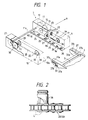
- Fig. 1 is a perspective view of a shifting means of a cassette loading device according to the present invention;
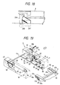
- Fig. 2 is a plan view showing a detailed portion of the shifting means of Fig. 1;
- Fig. 3 is a side sectional view of an image forming apparatus according to the present invention;
- Figs. 4 and 5 are side sectional views of the image forming apparatus for explaining the operation thereof;
- Fig. 6 is an elevational sectional view of the image forming apparatus according to the present invention;
- Fig. 7 is a block diagram showing a controlling portion;
- Fig. 8 is a perspective view of the image forming apparatus with a cassette retracted therefrom;
- Fig. 9 is a flow chart for explaining the operation of the cassette loading device;
- Fig. 10 is a block diagram showing a control means of a cassette loading device according to another embodiment of the present invention;
- Fig. 11 is a perspective view of a sheet accommodating means used with the cassette loading device of Fig. 10;
- Fig. 12 is an elevational sectional view showing a detecting means;
- Fig. 13 is a flow chart for explaining the operation of the cassette loading device of Figs. 10 - 12;
- Figs. 14A, 14B and 14C and Fig. 15 are views showing an alteration of the cassette loading device of Figs. 10 - 12;
- Figs. 16A, 16B and 16C are side sectional views showing a second shifting means of a further embodiment according to the present invention;
- Figs. 17A, 17B and 17C are side sectional views for explaining the operation of the second shifting means of Figs. 16A - 16C;
- Fig. 18 is a side sectional view showing an alteration of the shifting means of Figs. 16A - 16C;
- Fig. 19 is a perspective view of a cassette loading device according to a further embodiment of the present invention;
- Fig. 20 is a block diagram showing a control means of the cassette loading device of Fig. 19;
- Fig. 21 is a flow chart for explaining the operation of the cassette loading device of Figs. 19 and 20;
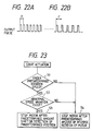
- Figs. 22A and 22B show pulse waves for the operation of the cassette loading device of Fig. 19;
- Figs. 23 and 24 are flow charts according to alterations of the cassette loading device of Fig. 19;
- Figs. 25A, 25B and 25C are side sectional views showing a further embodiment of a cassette loading device according to the present invention;
- Fig. 26 is a perspective view of the cassette loading device of Fig. 25A - 25C;
- Fig. 27 is a block daigram of a cassette loading device according to the other embodiment of the present invention;
- Fig. 28 is a perspective view of the cassette loading device of Fig. 27;
- Fig. 29 is an elevational sectional view of the cassette loading device of Fig. 28;
- Figs. 30 to 33 are side views of the device of Fig. 28 for explaining the operation thereof; and
- Fig. 34 is a flow chart associated with the cassette loading device of Fig. 28.
- The present invention will now be explained in connection with embodiments thereof with reference to the accompanying drawings.
- As shown in Figs. 3 to 6, an image forming apparatus as embodied as a
copying machine 1 comprises a shiftingdevice 5 by which acassette 3 is automatically loaded or unloaded with respect to amachine frame 2, and semi-circularsheet feed rollers 6 supported by aroller shaft 6a and adapted to feed a sheet from thecassette 3. Thefeed rollers 6 are positioned in the vicinity of the shiftingdevice 5. Further, aphotosensitive drum 7 supported by ashaft 7a is arranged within themachine frame 2, which drum can bear a toner image thereon. - As shown in Fig. 1, the
shifting device 5 comprisesframes 9 and 10, one of which (i.e., frame 9) includes areversible motor 11 arranged therein. Themotor 11 has amotor shaft 11a on which agear 12 is fixed, which gear 12 is meshed with agear 15 fixed to ashaft 13 rotatably supported by the frame 9. - On the other end of the shaft 13 a
sprocket 16 is fixed, which sprocket is operatively connected, through achain 20, to asprocket 19 fixed to ashaft 17 rotatably supported by the frame 9. Further, ashield plate 21 is arranged on links L of thechain 20, whichshield plate 21 is adapted to turn ON and OFF (i.e., activate and deactivate)sensors chain 20. Theframes 9, 10 haverail portions rollers 25 and acassette detecting sensor 26 are arranged. - The
motor shaft 11a of themotor 11 extends into theframe 10. On the free end of theshaft 11a agear 27 is fixed. Further, thegear 27 is meshed with agear 30 fixed to ashaft 29 rotatably supported by theframe 10. On the other end of the shaft 29 asprocket 31 is fixed, which sprocket is operatively connected, through achain 35, to asprocket 33 fixed to ashaft 32 rotatably supported by theframe 10. - The
chains chains cassette 3 is provided at its both front sides with L-shapedrecesses 37 adapted to receive thepins 36 of the chains. Incidentally, in Fig. 3, the reference symbol G designates an original (or manuscript) cover pivotable around a hinge H in a direction B. - As shwon in Fig. 7, the copying
machine 1 includes a controlling portion C, to an input portion of which thesensors cassette detecting sensor 26 and a cassette taking-out button 40 are connected; whereas themotor 11 is connected to an output portion of the controlling portion C. - In the illustrated embodiment, with the arrangement as mentioned above, when the
cassette 3 accommodating the sheets S therein is loaded within themachine frame 2, thepins 36 of the chains are positioned in a position where the pins face toentrance openings 37c (Fig. 4) of the corresponding L-shapedrecesses 37, i.e., a position where theshield plate 21 is detected by the sensor 22 (refer to Fig. 1). Accordingly, when thecassette 3 is inserted into the machine frame along therail portions pins 36 are introduced into the corresponding L-shapedrecesses 37. Further, when the bottom surface of thecassette 3 is supported on theoutermost roller 25, thepins 36 are aligned with thecorresponding entrance openings 37a of the L-shaped recesses, and then, whencassette 3 is shifted untilstraight portions 37e of therecesses 37 have passed through the corresponding pins 36, thecassette detecting sensor 26 is turned ON by the bottom surface of thecassette 3. - Consequently, the controlling portion C receives an ON signal from the
sensor 26, thereby driving themotor 11. The driving force from themotor 11 is transmitted to thesprocket 16 through thegears sprocket 31 through themotor shaft 11a and gears 27, 30. Subsequently, thechain 20 is rotated or turned in a clockwise direction through the rotation of thesprocket 16 and thechain 35 is turned through the rotation of thesprocket 31. - As a result of the rotation of the
chain pins 36 are firstly moved along arcuate paths to abut against correspondingvertical surfaces 37a of the L-shapedrecesses 37, and, thereafter, thepins 36 are shifted along straight paths in reponse to further rotation of thechains cassette 3 inwardly of the machine frame (in a direction D) as shown in Fig. 3. Accordingly, thecassette 3 is automatically inserted after it activates thecassette detecting sensor 26. Further, when thecassette 3 is inserted until theshield plate 21 turns thesensor 23 OFF, the controlling portion C receives an OFF signal from thesensor 23, thereby stopping themotor 11. In this point, since thepins 36 of thechains vertical surfaces 37a of the L-shapedrecesses 37 formed in thecassette 3, the latter is positioned in a predetermined position (Fig. 5). Fruther, in this point,inverted trapezoidal projections 3e formed on the bottom surface of thecassette 3 are fitted into corresponding positioning holes formed in therail portion 9a, thus positioning the cassette with respect to a direction perpendicular to the cassette inserting direction. It is more preferable that any braking means or locking means is provided in the motor or the gear train to maintain the cassette in the positioned condition. - On the other hand, when it is desired to unload the
cassette 3, the taking-out button 40 is activated or turned ON. Consequently, the braking means or locking means is deactivated or released, and, at the same time, the controlling portion C receives an ON signal from the taking-out button 40, thus rotating themotor 11 in a reverse direction to rotate thesprockets pins 36 of the chains abut against the othervertical surfaces 37b (opposed to the above-mentionedvertical surfaces 37a) of the L-shapedrecesses 37 to return thecassette 3 in the direction F. Thereafter, when thepins 36 is moved upwardly along the arcuate paths, the returning movement of thecassette 3 is stopped. - When the
pins 36 are returned to the position where theshield plate 21 deactivates (or turns OFF) thesensor 22, the controlling portion C receives an OFF signal from thesensor 22, thereby deactivating themotor 11 to stop the rotation of thechains pins 36 of the chains are positioned in the alignment with thestraight portions 37e having theentrance openings 37c of the L-shaped recesses 37 (see Fig. 4), thecassette 3 can be removed from themachine frame 2 by pulling the cassette rightwardly. - Incidentally, the
cassette 3 can be a pawl separating system as well as another type separating system. - Next, an operation of the copying machine will be explained with reference to a flow chart of Fig. 9. When a power source is turend ON, the controlling portion (not seen in Fig. 9) judges whether the
cassette detecting sensor 26 is turned ON or not (in a step S1); if yes, the controlling portion then judges whether thesensor 23 is turned ON or not (in a step S2). If it is judged that thesensor 23 is turned ON, the controlling portion then judges whether a copy start key (not shown) is turned ON or not (in a step S3); if yes, a sheet feed motor (not shown) is activated or turned ON (in a step S4). The activation of the sheet feed motor causes thefeed rollers 6 to rotate, thereby feeding the sheet S from thecassette 3. Then, the toner image formed on thephotosensitive drum 7 is transferred onto the sheet S, and then the image transferred on the sheet is fused or fixed to the sheet by means of a fixing device (not shown). Thereafter, the sheet is ejected from themachine frame 2. - After a predetermined number of sheets S are fed in the same manner, the controlling portion judges whether the sheet feeding is finished or not (in a step S5); if yes, the controlling portion turns the sheet feeding motor OFF, thereby stopping the sheet feeding operation (in a step S6). Further, the controlling portion judges whether a cassette taking-out key (not shown) is activated (turned ON) or not (in a step S7); if not, the controlling portion waits until the copy start key is turned ON.
- On the other hand, in the step S2, if it is judged that the
sensor 23 is not turned ON, the controlling portion drives thepulse motor 11 in the positive or normal direction to introduce thecassette 3 into the machine frame (in a step S8). The drive force from themotor 11 is transmitted to thesprocket 16 through thegears sprocket 31 through themotor shaft 11a and thegears sprockets chains pins 36 provided on the chains abut against thevertical surfaces 37a of the corresponding L-shapedrecesses 37 formed in the cassette, thereby shifting thecassette 3 toward the interior of the machine frame in response to the rotational movement of thechains sensor 23 is turned ON or not (in a step S9); if yes, thepulse motor 11 is turned OFF (in a step S10). In this way, thecassette 3 is reached to the predetermined position in themachine frame 2 by means of the shiftingdevice 5. Thereafter, the controlling portion executes the sequence from the above step S3 on. - On the other hand, in the step S9, if it is judged that the
sensor 23 is not turned ON, the controlling portion judges whether the cassette taking-out key is turned ON or not (in a step S11); if not, the controlling portion then executes the sequence from the above step S9 on. - On the other hand, if it is judged that the cassette taking-out key is turned ON, the controlling portion rotates the
pulse motor 11 in the reverse direction to shift thecassette 3 toward the outlet (in a step S12). The driving force from thepulse motor 11 is transmitted to thesprockets chains pins 36 of the chains abut against thevertical surfaces 37b of the corresponding L-shapedrecesses 37, thus shifting thecassette 3 toward the outlet. Then, the controlling portion judges whether thesensor 22 is turned ON or not (in a step S13); if yes, thepulse motor 11 is turned OFF (in a step S14). Then, the controlling portion judges whether thecassette detecting sensor 26 is tuned ON or not (in a step S15); if not, the sequence from the above step S1 is repeated. - On the other hand, in the step S7, if it is judged that the cassette taking-out key is turned ON, the sequence from the above step S12 is executed.
- Next, another embodiment of the present invention will be explained with reference to Figs. 10 to 15.
- Incidentally, it should be noted that the elements same as those explained in the previous embodiment are designated by the same reference numerals as used in the previous embodiment and the detailed explanation thereof will be omitted.
- As shown in Fig. 11, the
cassette 3 used with the copying machine has a sheetsize detecting block 39 removably mounted on a front surface (a forward surface with respect to the cassette inserting direction A) of the cassette. Theblock 39 serves to push one of sheetsize detecting switches machine frame 2. Further, theblock 39 can be changed to other block in accordance with the size of the sheets to be accommodated in the cassette. - Further, as shown in Fig. 12, an
attachment plate 41 is provided on a portion of themachine frame 2 opposed to theblock 39, whichattachment plate 41 is slidably supported by pins each having an enlarged free end and protruded from abracket 42 fixed to themachine frame 2. Acompression spring 45 is arranged around eachpin 43 between the enlarged end thereof and theattachment plate 41. The above-mentioned sheetsize detecting switches existence detecting switch 40d are arranged on theattachment plate 41. Further, thecassette 3 haspositioning spacers 46 for maintaining a predetermined distance between theattachment plate 41 and thecassette 3 itself, these spacers being situated outside of theswitch group 40a - 40d. - On the other hand, as shown in Fig. 10, the copying machine includes a controlling
portion 47 having an input portion connected to the sheetsize detecting switch existence detecting switch 40d,sensor 22 andcassette detecting sensor 26, and an output portion connected to thepulse motor 11. - Next, the operation of the copying machine according to this embodiment will be explained with reference to a flow chart shown in Fig. 13.
- In a condition that the
cassette 3 is loaded on the copying machine, signals from the sheetsize detecting switches existence detecting switch 40d,sensor 22 andcassette detecting sensor 26 are being sent to the controllingportion 47. Accordingly, on the basis of these signals, the controlling portion confirms the face that the cassette exists within the machine and is positioned in the predetermined position and detects the sheet size (in a step S1). - When the taking-out switch (not shown) is turned ON (in a step S2), the controlling
portin 47 receives an ON signal from the taking-out switch and determines the number of pulses corresponding to the sheet size (in a step S3), thereby actuating thepulse motor 11 by such number of pulses (in a step S4). Consequently, thesprockets pins 36 of the chains against thevertical surfaces 37b of the corresponding L-shapedrecesses 37 formed in the cassette, thus shifting thecassette 3 toward the outlet (in the direction F in Fig. 3). After thepulse motor 11 is rotated by the predetermined pulses, thepulse motor 11 is stopped. In this point, thecassette 3 is retracted or protruded from themachine frame 2 by a distance corresponding to the sheet size. In this way, the taking-out of the cassette is finished (in a step S5). - On the other hand, when the
cassette 3 accommodating the sheets S therein is inserted into themachine frame 2, since thepins 36 of the chains are aligned with theentrance openings 37c of the corresponding recesses 37, thepins 36 can be introduced into the correspondingrecesses 37 by inserting thecassette 3 along therail portions cassette detecting sensor 26 ON, the controlling portion receives the ON signal from thecassette detecting sensor 26, thereby actuating thepulse motor 11. - The driving force from the
pulse motor 11 is transmitted to thesprocket 16 through thegears sprocket 31 through themotor shaft 11a and thegears sprockets chains pins 36 of the chains abut against thevertical surfaces 37a of the corresponding recesses 37 formed in the cassette, thereby shifting thecassette 3 toward the interior of the machine frame (in the direction D) (refer to Fig. 3) in response to the rotational movement of thechains shield plate 21 turns thesensor 22 OFF, the controllingportion 47 receives the OFF signal from thesensor 22, thereby stopping thepulse motor 11. In this way, thecassette 3 is positioned in the predetermined position. - Incidentally, in the above-mentioned embodiment, while the cassette was illustrated as a cassette of universal type, but the present invention is not limited to the use of such cassette. For example, as shown in Figs. 14A, 14B and 14C,
different cassettes cassettes recesses 37 formed therein at different positions, respectively. The cassette 3a is used for receiving the sheets having large size, thecassette 3b is used for receiving the sheets having intermediate size, and thecassette 3c is used for receiving the sheets having small size. - In case where
such cassettes microswitch 50 is provided for detecting the fact that thecassettes cassette 3c corresponding to the sheet having the small size is loaded on themachine frame 2, as thecassette 3c is introduced into the machine frame until thepins 36 abut against thevertical surfaces 37b of the corresponding L-shapedrecesses 37, afirst projection 3g formed on the bottom surface of the cassette at a predetermined position turns thecassette detecting sensor 26 ON. Consequently, thecassette 3c is shifted toward the interior of the machine frame in the same manner as mentioned above. Then, when a second projection (not shown) formed on the cassette at a predetermined position turns themicroswitch 50 ON, thepulse motor 11 is stopped, thus completing the loading of the cassette. Incidentally, as shown in Figs. 14A to 14C, thefirst projection 3g is provided at a different position for eachcassette cassette 3c is unloaded from the machine frame, the cassette is shifted toward the outlet in the same manner as mentioned above. Then, when the first projecting 3g is disengaged from thecassette detecting sensor 26, thepulse motor 11 is turned OFF. In this way, thecassette 3c is retracted up to a position where the sheets having the small size (ℓ₁ in Fig. 8) can easily be replenished. - Next, a further embodiment of the present invention wll be explained with reference to Figs. 16 - 18.
- Incidentally, it should be noted that the elements same as those explained in the previous embodiments are designated by the same reference numerals as used in such previous embodiments and the detailed explanation thereof will be omitted.
- As shown in Fig. 16A, the copying machine includes an
arm 139 rotatably supported by amachine frame 2a. An intermediate portion of thearm 139 is connected to one end of abias spring 140, the other end of which is connected to themachine frame 2a. In this way, thearm 139 is normally held in a cocked or upright condition. Further, acassette detecting sensor 141 is arranged in the vicinity of a base end of thearm 139, whichsensor 141 is adapted to be activated or deactivated (ON or OFF) by means of aprojection 139a of thearm 139. Further, arotatable roller 142 is rotatably mounted on a free end of thearm 139. - In the illustrated embodiment, with the arrangement as mentioned above, when the
cassette 3 is loaded on themachine frame 2a, since thepins 36 of the chains are aligned with theentrance openings 37c of the corresponding recesses 37, thepins 36 can be introduced into the correspondingrecesses 37 by inserting thecassette 3 along therail portions arm 139 is rotated in an anti-clockwise direction in opposition to the bias force of thespring 140 in response to the movement of the cassette (refer to Fig. 16B). Then, when theroller 142 provided on the free end of thearm 139 abuts against the bottom surface of thecassette 3, theprojection 139a of thearm 139 blocks an optical path between a light source and a light receiving portion of thecassette detecting sensor 141. - Then, by a signal from the
sensor 141, thepulse motor 11 is rotated in the normal direction. The driving force from themotor 11 is transmitted to thechains chains pins 36 are abutted against thevertical surfaces 37a of the corresponding recesses 37, thereby shifting thecassette 3 toward the interior of the machine frame (refer to Fig. 16C). Thereafter, thecassette 3 is shifted to the predetermined position and is positioned at that position in the same manner as previously mentioned. - On the other hand, when the
cassette 3 is unloaded from the machine frame, as a taking-out button (not shown) is turned ON, thepulse motor 11 is rotated in the reverse direction in response to a signal from the taking-out button, thereby rotating thesprockets pins 36 of the chains are abutted against thevertical surfaces 37b of the corresponding L-shapedrecesses 37 of the cassette, thus shifting thecassette 3 toward the outlet (refer to Fig. 17A). Then, when thecassette detecting sensor 141 is turned OFF, thepulse motor 11 is deactivated in response to an OFF signal from thesensor 141, thus finishing the shifting movement of the cassette 3 (refer to Fig. 17B). Then, thecassette 3 is further shifted toward the outlet through the rotation of thearm 139 caused by the bias force of thespring 140, whereby theprojection 139a of thearm 139 is retarded from the optical path between the light source and the light receiving portion of thecassette detecting sensor 141, thus turning thesensor 141 ON (refer to Fig. 17C). In this way, the copying machine becomes a waiting condition for receiving thecassette 3, in response to the ON signal from thesensor 141. - Incidentally, in this embodiment, while an example that the
cassette detecting sensor 141 which is turned ON and OFF by theprojection 139a of thearm 139 is used as a detecting means was explained, the present invention is not limited to such example. For example, as shown in Fig. 18, acassette detecting sensor 241′ which can be turned ON and OFF by means of thecassette 3 itself. In this case, thearm 239 connected to thebias spring 240 has no projection. - Next, a still further embodiment of the present invention will be explained with reference to Figs. 19 to 24.
- As shown in Fig. 19, a
cassette shifting device 5 comprisesframes 9 and 10, one of which (i.e., frame 9) includes areversible motor 11 arranged therein. Themotor 11 has amotor gear 11a on which agear 12 is fixed, which gear 12 is meshed with agear 15 fixed to ashaft 13 rotatably supported by the frame 9. Asprocket 16 is fixed to the other end of theshaft 13, which sprocket 16 is operatively connected, through achain 20, to asprocket 19 fixed to ashaft 17 rotatably supported by the frame 9. Further, ashield plate 21 is arranged on thechain 20, whichshield plate 21 is adapted to turn ON and OFF (i.e., activate and deactivate)sensors chain 20. - The frame 9 has a
rail portion 9a on which guiderollers 25 and acassette detecting sensor 26 are arranged, whereas theframe 10 has arail portion 10a on which guiderollers 25 are arranged. Further, aslitted disc 357 is fixed to one end of themotor shaft 11a of themotor 11, and a photo-interrupter 356 is arranged in the vicinity of thedisc 357. The other end of themotor shaft 11a extends into theframe 10 and has agear 27 fixed thereto. Further, thegear 27 is meshed with agear 30 fixed to ashaft 29 rotatably supported by theframe 10. Asprocket 33 is fixed on the other end of theshaft 29, which sprocket is operatively connected, through achain 35, to asprocket 33 fixed to ashaft 32 rotatably supported by theframe 10. - The chains have
pins 36 which can be moved together with the chains in response to the rotation of thechains cassette 3 is provided at its both front sides with laid L-shapedrecesses 37 adapted to receive thepins 36 of the chains. - As shown in Fig. 20, the copying
machine 1 includes a controllingportion 355, to an input portion of which thesensors cassette detecting sensor 26 and the photo-interrupter 356 are connected; whereas themotor 11 is connected to an output portion of the controllingportion 355. Incidentally, theslitted disc 357 and the photo-interrupter 356 may be arranged at a position where theseelements 356, 257 can sense thesprocket - In the illustrated embodiment, with the arrangement as mentioned above, when the
cassette 3 accommodating the sheets S therein is loaded within themachine frame 2, thepins 36 of the chains are positioned in a position where the pins face toentrance openings 37c (Fig. 4) of the corresponding L-shapedrecesses 37. Accordingly, when thecassette 3 is inserted into the machine frame along therail portions pins 36 are introduced into the corresponding L-shapedrecesses 37. Then, when the bottom surface of thecassette 3 turns thecassette detecting sensor 26 ON, the controllingportion 355 receives an ON signal from thesensor 26, thereby driving themotor 11. The driving force from themotor 11 is transmitted to thesprocket 16 through thegears sprocket 31 through themotor shaft 11a and gears 27, 30. Subsequently, thechain 20 is rotated or turned through the rotation of thesprocket 16 and thechain 35 is turned through the rotation of thesprocket 35. As a result of the rotation of thechains pins 36 abut against correspondingvertical surfaces 37a of the L-shapedrecesses 37, thus shifting thecassette 3 toward the interior of the machine frame in response to the rotational movement of thechains - In this case, the controlling
portion 355 executes the sequence shown in a flow chart of Fig. 21. - The controlling
portion 355 judges, on the basis of a signal from the photo-interrupter, whether the motor is rotated at a predetermined speed, i.e., whether output pulses from the photo-interrupter 356 is regularly emitted at the predetermined timing (t) (refer to Fig. 22A) (in a step S1); if yes, the controlling portion judges whether there exists abnormal speed variation of the motor (in a step S2). If it is judged that the abnormal speed variation does not exist, the controllingportion 355 continues to shift thecassette 3. When theshield plate 21 turns thesensor 22 OFF, themotor 11 is stopped (in a step S3). In this way, thecassette 3 is positioned at a predetermined position. - When a start key (not shown) is depressed after an original or manuscript is laid on a platen (not shown), an image on the original is read by an optical system (not shown) comprising a lamp, mirrors and lenses, thus forming a latent image on a photosensitive drum in an image forming portion (not shown). An uppermost sheet S is separated from the sheet stack accommodated in the
cassette 3 by a separating pawl (not shown), and the uppermost sheet is fed out from the cassette by a feed roller (not shown). Then, the sheet S is fed to a pair of regist rollers (not shown) by means of a pair of feeding rollers (not shown) until the sheet S reaches the nip between the regist rollers. After the sheet abuts against the nip between the regist rollers, the sheet is subjected to the feeding force due to the feeding rollers with slipping action, thus correcting the skew-feeding of the sheet. Then, the sheet S is further fed in synchronous with the movement of the image on the photosensitive drum by means of the regist rollers rotating at the predetermined timing. Then, the image (toner image) on the photosensitive drum is transferred onto the sheet S. Thereafter, the sheet is fed to a fixing or fusing device (not shown) by means of feeding belts (not shown), where the transferred image is fixed to the sheet. Then, the sheet is ejected onto an ejector tray (not shown) by means of a pair of ejector rollers (not shown). Such a series of operations from the feeding of the sheet to the ejecting the sheet may be performed in a conventional manner. - Incidentally, in the above-mentioned step S1, if it is judged that the motor is not rotated at the predetermined speed, i.e., if it is judged that any load is applied to the motor at the beginning to prevent the regular emission of the output pulses of the photo-
interrupter 356 at the predetermined timing t (i.e., t < t′) (refer to Fig. 22B), the controllingportion 355 stops the motor 11 (in a step S4). Further, in the above-mentioned step S2, if it is judged that there exists the abnormal speed variation due to irregularity of the duration between the output pulses, i.e., if the excessive load is applied to the shifting device during the insertion of the cassette, the controllingportion 355 stops themotor 11 and at the same time emits an warning signal E to indicate the abnormity to an operator. Accordingly, the operator can eliminate the abnormity by removing the cassette from the copying machine manually. - Incidentally, in the illustrated embodiment, while an example that, if the motor is not rotated at the predetermined speed and/or if there exists the abnormal speed variation, the controlling
portion 355 stops the motor 11 (or disengage any clutch between in the driving path to stop the chains without stopping the motor) was explained, the present invention is not limited to such example. For example, as shown in a flow chart of Fig. 23, if the above abnormal conditions occur, themotor 11 may be stopped after it is rotated at a predetermined amount in the reverse direction. With this arrangement, since the motor is stopped after the cassette is retarded from the abnormal condition, the damage of the cassette and/or copying machine can be prevented. Further, even if the operator's hand gets in between the cassette and the machine frame, he can easily draw out his hand by pulling the cassette toward the outlet. - Alternatively, as shown in a flow chart of Fig. 24, the motor may be rotated in the reverse direction to return the
cassette 3 to the actuation start position. In this case, the cassette can be retarded from the abnormal condition and such abnormal condition can be warned, and such abnormal condition can be corrected quickly. - Incidentally, the predetermined amount of reverse rotation of the motor can be performed by rotating the
motor 11 in the reverse direction for a predetermined time through any timer circuit when any signal regarding the excessive load is emitted. On the other hand, the returning of the cassette to the actuation start position can be performed by returning theshield plate 21 to a position where it shields thesensor 22. - Further, in the illustrated embodiment, while an example that the
slitted disc 357 and the photo-interrupter 356 are used as the detecting means to detect the rotational speed of themotor shaft 11a of themotor 11, thereby detecting the presence of the excessive load was explained, the present invention is not limited to such example. For example, a current detector for detecting a current value of themotor 11 may be used as the detecting means to detect the excessive load. In this case, when the current value exceeds a predetermined value, the controllingportion 355 confirms the fact that the excessive load occurs, thereby stopping themotor 11. - Further, after the abnormal condition is detected and then the cassette is returned by the predetermined amount or to the actuation start position, the detection of the abnormal condition may be reset. With this arrangement, if the operator's hand gets in between the cassette and the machine frame, after he draws out his hand, by pushing the cassette again, the cassette can automatically be re-loaded on the machine frame by means of the motor. Alternatively, the detection of the abnormal condition may be reset when the
sensor 26 is turned OFF by withdrawing the cassette completely. - Incidentally, it is guessed that the excessive load is generated due to penetration of foreign matters in the cassette moving path, poor retraction of the sheet feeding means, mis-alignment between the cassette and the insertion position, insertion of the operator's hand between the cassette and the machine frame, error in loading of the sheets in the cassette, overload of the sheets in the cassette, or the like.
- Next, a still further embodiment of the present invention will be explained with reference to Figs. 25 and 26.
- Incidentally, it should be noted that the elements same as those explained in the previous embodiments are designated by the same reference numerals as used in such previous embodiments and the detailed explanation thereof will be omitted.
- As shown in Fig. 26, a
cassette shifting device 5a includes frames 9′ and 10′. The frame 9′ is constituted by a lower frame portion 9′b and an upper frame portion 9′c which can be slidably moved with respect to the lower frame portion 9′b in the directions A and B. Similarly, theframe 10′ is constituted by alower frame portion 10′b and anupper frame portion 10′c which can be slidably moved with respect to thelower frame portion 10′b in the directions A and B. Further, theupper frame portion 10′c has arack 455 arranged thereon, and ascrew 456 meshed with therack 455 is fixedly mounted on thelower frame portion 10′b. Although not shown in the drawings, similarly, the upper frame portion 9′c and the lower frame portion 9′b of the frame 9′ have a rack and a screw, respectively, which are meshed with each other. Further, the lower frame portion 9′b includes a rail portion 9′a having an inward upright end wall on which one end of aspring 457 is fixedly mounted. Anabutment plate 459 is fixed to the other or free end of thespring 457, which abutment plate is adapted to abut against thecassette 3. Similarly, thelower frame portion 10′b includes asimilar rail portion 10′a having a similar abutment plate. - In the illustrated embodiment, with the arrangement as mentioned above, when the
cassette 3 accommodating the sheet S therein is loaded within the machine frame, since thepins 36 of the chains face to theentrance openings 37c of the corresponding L-shaped recesses of the cassette, as thecassette 3 is inserted into the machine frame along the rail portions 9′a, 10′a, thepins 36 can be introduced into the corresponding L-shapedrecesses 37. Further, when the bottom surface of thecassette 3 is supported on theoutermost guide roller 25, thepins 36 are aligned with thecorresponding entrance openings 37c of the L-shapedrecesses 37, and then, when thecassette 3 is shifted until thestraight portions 37d of the L-shapedrecesses 37 have passed through the corresponding pins 36, thecassette detecting sensor 26 is turned ON by the bottom surface of the cassette 3 (refer to Fig. 25A). Consequently, the controlling portion receives an ON signal from thesensor 26, thereby actuating themotor 11. The driving force from themotor 11 is transmitted to thesprocket 16 through thegears sprocket 31 through themotor shaft 11a and thegears - Subsequently, the
chain 20 is rotated in the clockwise direction through the rotation of thesprocket 16 and thechain 35 is also rotated through the rotation of thesprocket 31. As a result of the rotation of thechains pins 36 are firstly moved along arcuate paths to abut against the correspondingvertical surfaces 37a of the L-shapedrecesses 37, and, thereafter, thepins 36 are shifted along straight paths in response to further rotation of thechains cassette 3 is automatically shifted after it activates thecassette detecting sensor 26. As thecassette 3 is further shifted inwardly, an inward end wall of thecassette 3 abuts against theabutment plates 459, and thereafter, the cassette is further shifted inwardly while compressing thesprings 457. Then, when thepins 36 reaches its innermost position on the chains (refer to Fig. 25C), theshield plate 21 turns thesensor 22 OFF. Incidentally, although the cassette is subjected to the returning force due to the compression of thesprings 457, since thevertical surfaces 37a of the L-shapedrecesses 37 of the cassette abut against the corresponding pins 36, the cassette is prevented from returning toward the outlet. Accordingly, the cassette is positioned correctly. Further, since thepins 36 of the chains are positioned symmetrically with respect to the upper and lower runs of the corresponding chains (see Fig. 25C), the returning force of the compressed springs does not act on the chains. - Incidentally, the position of the
cassette 3 with respect to themachine frame 2 can be finely adjusted by rotating thescrews 456 to move theracks 455 thereby shifting the upper frame postions 9′c, 10′c of the frames 9′, 10′ with respect to the lower frame portions 9′b, 10′b in the direction A or B. - In the illustrated embodiments, while the
chains sprockets - Lastly, the other embodiment of the present invention will be explained with reference to Figs. 27 to 34.
- As shown in Fig. 28 the
shifting device 5 comprisesframes 9 and 10, one of which (i.e., frame 9) includes areversible motor 11 arranged therein. Themotor 11 has amotor shaft 11a on which agear 12 is fixed, which gear 12 is meshed with agear 15 fixed to ashaft 13 rotatably supported by the frame 9. On the other end of the shaft 13 asprocket 16 is fixed, which sprocket is operatively connected, through achain 20, to asprocket 19 fixed to ashaft 17 rotatably supported by the frame 9. - A
shield plate 21 is arranged on links L (refer to Fig. 2) of thechain 20, whichshield plate 21 is adapted to turn ON or OFF (i.e., activate or deactivate)sensors chain 20. Theframes 9, 10 haverail portions rollers 25 and acassette detecting sensor 26 are arranged. Further, themotor shaft 11a of themotor 11 extends into theframe 10. On the free end of theshaft 11a agear 27 is fixed. Further, thegear 27 is meshed with agear 30 fixed to ashaft 29 rotatably supported by theframe 10. On the other end of the shaft 29 asprocket 31 is fixed, which sprocket is operatively connected, through achain 35, to asprocket 33 fixed to ashaft 32 rotatably supported by theframe 10. - The
chains chains cassette 3 is provided at its both front sides with laid L-shapedrecesses 37 adapted to receive thepins 36 of the chains. Anabutment plate 555 against which the cassette can abut is fixed to inner ends of theframes 9 and 10. Acassette sensor 556 for detecting the fact that thecassette 3 reaches the sheet feeding position is arranged on theabutment plate 555. Incidentally, thereference numeral 62 designates a sheet separating pawl. - Further, as shown in Fig. 29, a
spring 557 one end of which is fixed to thevertical surface 37a is arranged in each L-shapedrecess 37 of the cassette. Thesprings 557 serve to compensate discrepancy in positions of thepins 36. - As shown in Fig. 27, the copying
machine 1 includes a controllingportion 559, to an input portion of which thesensors cassette detecting sensor 26 and acassette sensor 556 are connected; whereas themotor 11 is connected to an output portion of the controllingportion 559. Particularly, thesensor 23 acts as an outward home position sensor, and thesensor 22 acts as an inward home position sensor. ON or OFF signals from thesensors portion 559, and the controlling portion controls the normal or reverse rotation of themotor 11 properly on the basis of these signals. - In the illustrated embodiment, with the arrangement as mentioned above, when the
cassette 3 accommodating the sheets S therein is loaded within themachine frame 2, thepins 36 are positioned in a position where they face to theentrance openings 37c (Fig. 30) of the L-shapedrecesses 37 of the cassette and is positioned on the chain portion wrapping around the sprocket 19 (Fig. 28). This position of thepins 36 is always ensured by stopping themotor 11 at a predetermined time after theshield plate 21 is detected by thehome position sensor 23. - On the other hand, each entrance opening 37c of the corresponding L-shaped
recesses 37 of the cassette is formed in a position where, when thecassette 3 is situated on therail portions pin 36 can be smoothly inserted into the corresponding L-shapedrecess 37. Accordingly, as thecassette 3 is inserted into the machine frame along therail portions pins 36 can be introduced into the corresponding recesses 37. When the bottom surface of thecassette 3 is supported on theoutermost roller 25, thepins 36 are aligned with thecorresponding entrance openings 37a of the L-shaped recesses, and then, whencassette 3 is shifted untilstraight portions 37d of therecesses 37 have passed through the corresponding pins 36, thecassette detecting sensor 26 is turned ON by the bottom surface of thecassette 3. - Consequently, the controlling
portion 559 receives an ON signal from thesensor 26, thereby driving themotor 11. The driving force from themotor 11 is transmitted to thesprocket 16 through thegears sprocket 31 through themotor shaft 11a and gears 27, 30. - Subsequently, the
chain 20 is rotated in a clockwise direction through the rotation of thesprocket 16 and thechain 35 is rotated through the rotation of thesprocket 35. As a result of the rotation of thechains pins 36 are firstly moved along arcuate paths to abut against the correspondingsprings 557 attached to thevertical surfaces 37a of the L-shaped recesses 37 (refer to Fig. 28), and, thereafter, thepins 36 are shifted along straight paths in response to further rotation of thechains cassette 3 inwardly of the machine frame (in a direction A) (refer to Fig. 6). Accordingly, thecassette 3 is automatically inserted after it activates thecassette detecting sensor 26. - Further, as the
cassette 3 is further shifted inwardly of the machine frame, the inward end wall of thecassette 3 abuts against theabutment plate 555 to turn thecassette sensor 556 ON (Fig. 32). In this point, thesensor 22 has not yet been turned OFF by theshield plate 21, and, therefore, the controllingportion 559 continues to rotate themotor 11. When theshield plate 21 turns thesensor 22 OFF (Fig. 33), the controllingportion 559 receives an OFF signal from thesensor 22, thereby stopping themotor 11. In this point, since thepins 36 of the chains compress thesprings 557 and abut against the correspondingvertical surfaces 37a of the L-shapedrecesses 37 with the interposition of the compressed springs, the cassette is positioned in a predetermined position (Fig. 5). Incidentally, it is more preferable that any braking means or locking means is provided in the motor or the gear train to maintain the cassette in the positioned condition. - On the other hand, when it is desired to unload the
cassette 3, the operator slightly pulls the cassette outwardly (in the direction B) while further compressing thesprings 557. Consequently, the inward end wall of thecassette 3 is separated to turn thecassette sensor 556 OFF. Then, the controllingportion 559 receives an OFF signal from thesensor 556, thereby deactivating the braking means or locking means, and at the same time, rotating themotor 11 in the reverse direction to rotate thesprockets pins 36 of the chains abut against the othervertical surface 37b (opposed to the above-mentionedvertical surfaces 37a) of the L-shapedrecesses 37, thus shifting thecassette 3 toward the outlet (in the direction B). Thereafter, since thepins 36 of the chains are moved upwardly along the arcuate paths, the returning movement (toward the outlet) of thecassette 3 is stopped. Then, thepins 36 are moved to the position where theshield plate 21 turns thesensor 23 OFF, the controllingportion 559 receives the OFF signal from thesensor 23, thus stopping themotor 11 to thereby stop the movement of thechains - Next, the operation of the copying machine according to this embodiment will be explained with reference to a flow chart of Fig. 34. First of all, it is assumed that the cassette is set or loaded within the machine frame (step S1). In this condition, the
cassette switch 556 is turned ON,sensor 23 is turned ON,sensor 22 is turned OFF, cassette detecting sensor is turned ON, and eject key is turned OFF, andmotor 11 is turned OFF. For example, here, when the cassette is pulled outwardly, the controlling portion judges whether thecassette detecting sensor 26 is turned from ON to OFF (in a step S2); if yes, the controlling portion actuates the motor in the reverse direction, i.e., in the feed out direction (in a step S3). Consequently, the cassette is shifted toward the outlet. Meanwhile, when thesensor 23 is turned from ON to OFF, this fact is judged by the controlling portion (in a step S4), whereby the motor is turned OFF (in a step S5) to finish the feed-out of the cassette (in a step S6). - In this point, the braking means or locking means is activated again to hold the
pins 36 in the stopped position. Since, in this point, thepins 36 are positioned in thestraight portions 37d (Fig. 30) parallel to theentrance openings 37c and above thevertical surfaces 37a of therecesses 37, the cassette can easily be removed from the machine frame by pulling the cassette outwardly. - Incidentally, it may be so designed that the presence of the
cassette 3 is detected by thecassette sensor 556 and is displayed on an operation panel. With this arrangement, thecassette sensor 556 can be utilized more effectively. Further, by constructing so that a timer is activated after a taking-out key is depressed, whereby the cassette taking-out movement is performed with a little delay, the operation of the taking-out key can be utilized together with the above operations. - While the present invention was explained in connection with various embodiments thereof, it should be noted that any combination of these embodiments can be adopted to the present invention.
- The present invention provides a cassette loading device for an image forming apparatus including a sheet feeding portion within which a cassette for accommodating sheets is loaded, and a sheet feeding means arranged in the sheet feeding portion and adapted to feed the sheet from the cassette loaded within the sheet feeding portion. The cassette loading device comprises a guide means for guiding the cassette to be loaded; a cassette shifting means rotatable along the guide means and having pins engageable with the cassette inserted into the sheet feeding portion; a driving means for driving the cassette shifting means; vertical surfaces formed in the cassette and against which the pins are abutted to shift the cassette; and horizontal recesses formed in the cassette and adapted to direct the pins toward the vertical surfaces. The present invention further provides an image forming apparatus which includes an image forming means for forming an image on the sheet being fed, and the above-mentioned cassette loading device.
Claims (13)
- A cassette loading device for an image forming apparatus including a sheet feeding portion, said cassette loading device comprising at least one cassette (3) for accommodating sheets (S) which is loaded within said sheet feeding portion, said cassette loading device further comprising:
a guide means (25) for guiding said cassette (3) to be loaded;
a cassette shifting means (20, 35) rotatable along said guide means and having engagement members (36) engageable with said cassette (3) inserted into said sheet feeding portion;
a driving means (11) for driving said cassette shifting means (20, 35); wherein said cassette (3) has engagement surfaces (37a, 37b) against which said engagement members (36) are abutted to shift said cassette,
characterized in that
said cassette (3) further comprises passages (37c, 37d, 37e) adapted to direct said engagement members (36) toward said engagement surfaces (37a, 37b). - A cassette loading device according to claim 1, characterized in that said engagement surfaces and said passages define laid L-shaped recesses (37) formed in said cassette.
- A cassette loading device according to claim 1, characterized in that said cassette shifting means (20, 35) comprises chains (20, 35) and said engagement members (36) comprise pins (36) arranged on the respective chains.
- A cassette loading device according to claim 1, further including a first switch (26) arranged in a cassette shifting path (9a, 10a), wherein said switch is actuated when said cassette (3) is inserted, thereby activating said driving means (11) to shift said cassette.
- A cassette loading device according to claim 1, further including a second switch (23) arranged in a cassette shifting path (9a, 10a), wherein said switch is actuated when said cassette (3) is returned, thereby deactivating said driving means (11).
- A cassette loading device according to claim 1, further including a sheet size detecting means (40a, 40b, 40c) and a control means (47) for controlling an amount of returning movement of said cassette (3) by controlling said driving means (11) on the basis of sheet size information from said sheet size detecting means.
- A cassette loading device according to claim 1, further including a detecting means (556) for detecting the fact that said cassette (3) loaded within said sheet feeding portion is slightly retracted and a control means (559) for controlling said driving means (11) in response to a signal from said detecting means to drive said cassette shifting means (20, 35) in a reverse direction.
- A cassette loading device according to claim 1, further including a detecting means (356, 357) for detecting variation in load of said driving means (11) and a control means (355) for stopping or reversing said driving means (11) when it receives a load increase signal from said detecting means (356, 357).
- A cassette loading device according to claim 1, characterized in that said cassette shifting means (20, 35) comprises elliptical endless chains (20, 35) and said engagement members (36) comprise pins (36) provided on said chains, wherein it further includes a control means (C) for stopping said driving means (11) when said pins are positioned at a position corresponding to a position where said cassette (3) is loaded within said sheet feeding portion.
- A cassette loading device according to claim 1, further including an elastic returning means (557) for returning said cassette shifting means (20, 35) by an elastic force after said cassette shifting means is returned by said driving means (11) and is stopped.
- A cassette loading device according to claim 1, characterized in that a sheet feeding direction is perpendicular to a cassette loading direction.
- A cassette loading device according to claim 1, wherein said cassette shifting means (20, 35) comprises elliptical endless chains (20, 35) and said engagement members (36) comprise pins (36) provided on said chains, and wherein a home position of each of said pins is situated in a position where each of said pins is opposed to said respective horizontal passages (37c).
- An image forming apparatus including a cassette loading device according to any of claims 1 to 12;
an image forming means (7) for forming an image on said sheet being fed;
a sheet feeding means (6) arranged in said sheet feeding portion and adapted to feed a sheet from said cassette loaded within said sheet feeding portion.
Applications Claiming Priority (12)
| Application Number | Priority Date | Filing Date | Title |
|---|---|---|---|
| JP63265653A JPH0790925B2 (en) | 1988-10-20 | 1988-10-20 | Image forming device |
| JP265653/88 | 1988-10-20 | ||
| JP63266886A JPH0790926B2 (en) | 1988-10-21 | 1988-10-21 | Image forming device |
| JP266886/88 | 1988-10-21 | ||
| JP63271817A JPH0790927B2 (en) | 1988-10-26 | 1988-10-26 | Image forming device |
| JP271817/88 | 1988-10-26 | ||
| JP27789888A JPH02123034A (en) | 1988-11-01 | 1988-11-01 | Sheet storage vessel conveyer |
| JP277898/88 | 1988-11-01 | ||
| JP5654/89 | 1989-01-11 | ||
| JP1005654A JPH02188323A (en) | 1989-01-11 | 1989-01-11 | Image forming device |
| JP9061/89 | 1989-01-18 | ||
| JP1009061A JPH0818712B2 (en) | 1989-01-18 | 1989-01-18 | Image forming device |
Publications (3)
| Publication Number | Publication Date |
|---|---|
| EP0365035A2 EP0365035A2 (en) | 1990-04-25 |
| EP0365035A3 EP0365035A3 (en) | 1991-06-12 |
| EP0365035B1 true EP0365035B1 (en) | 1994-09-21 |
Family
ID=27547924
Family Applications (1)
| Application Number | Title | Priority Date | Filing Date |
|---|---|---|---|
| EP89119529A Expired - Lifetime EP0365035B1 (en) | 1988-10-20 | 1989-10-20 | Cassette loading device for image forming apparatus |
Country Status (3)
| Country | Link |
|---|---|
| US (1) | US5100123A (en) |
| EP (1) | EP0365035B1 (en) |
| DE (1) | DE68918386T2 (en) |
Families Citing this family (16)
| Publication number | Priority date | Publication date | Assignee | Title |
|---|---|---|---|---|
| US5253941A (en) * | 1990-08-21 | 1993-10-19 | Sony Corporation | Transfer/recording paper cartridge |
| IT1257370B (en) * | 1992-01-30 | 1996-01-15 | Olivetti Canon Ind Spa | AUTOMATIC OPENING PAPER WAREHOUSE FOR A COPYING MACHINE OSIMILE OFFICE MACHINE. |
| JP2680510B2 (en) * | 1992-06-26 | 1997-11-19 | シャープ株式会社 | Cassette size detection mechanism |
| JP2666104B2 (en) * | 1992-09-16 | 1997-10-22 | 三田工業株式会社 | Paper cassette support device |
| US5841362A (en) * | 1995-02-10 | 1998-11-24 | Canon Kabushiki Kaisha | Optional apparatus connectable to other apparatus |
| KR100209517B1 (en) * | 1996-05-25 | 1999-07-15 | 윤종용 | Laser beam printer with variable sheet feeding capacity |
| JP3219707B2 (en) * | 1996-12-24 | 2001-10-15 | キヤノン株式会社 | Sheet material transport device and image processing device |
| US6421139B1 (en) | 1997-02-28 | 2002-07-16 | Canon Kabushiki Kaisha | Image forming apparatus for forming image on free-size sheet having arbitrary size |
| JP3387813B2 (en) | 1998-03-06 | 2003-03-17 | キヤノン株式会社 | Image forming apparatus provided with document feeder |
| US6631986B2 (en) * | 1998-12-16 | 2003-10-14 | Silverbrook Research Pty Ltd | Printer transport roller with internal drive motor |
| JP4015777B2 (en) * | 1999-03-31 | 2007-11-28 | 富士フイルム株式会社 | Container misinsertion prevention structure and container processing apparatus |
| DE10209602B4 (en) * | 2002-03-05 | 2007-12-13 | Heidelberger Druckmaschinen Ag | Device for transferring cassettes for printing plates |
| JP4446862B2 (en) * | 2004-11-09 | 2010-04-07 | 京セラミタ株式会社 | Paper feeding device for image forming apparatus |
| JP4257540B2 (en) * | 2006-01-31 | 2009-04-22 | ブラザー工業株式会社 | Image recording device |
| JP5042810B2 (en) * | 2007-12-27 | 2012-10-03 | 株式会社リコー | Paper feeding device and image forming apparatus |
| JP6892631B2 (en) * | 2017-03-27 | 2021-06-23 | セイコーエプソン株式会社 | Media processing equipment |
Family Cites Families (7)
| Publication number | Priority date | Publication date | Assignee | Title |
|---|---|---|---|---|
| US3409292A (en) * | 1967-01-02 | 1968-11-05 | Hope Henry | Machine for feeding x-ray film or the like |
| JPS6134363Y2 (en) * | 1980-08-18 | 1986-10-07 | ||
| JPS60148842A (en) * | 1984-01-11 | 1985-08-06 | Canon Inc | Sheet cassette supply apparatus |
| US4780740A (en) * | 1985-04-02 | 1988-10-25 | Kentek Information Systems, Inc. | Paper feeding cassette for a printing apparatus |
| DE3610659C1 (en) * | 1986-03-29 | 1987-03-26 | Agfa Gevaert Ag | Roentgenblattfilmassette- and loading device |
| GB2196942B (en) * | 1986-09-18 | 1991-07-17 | Canon Kk | A sheet conveying apparatus |
| CA1311508C (en) * | 1987-01-07 | 1992-12-15 | Izumi Seto | Automatic machine for unloading film sheet from magazine |
-
1989
- 1989-10-18 US US07/423,786 patent/US5100123A/en not_active Expired - Lifetime
- 1989-10-20 EP EP89119529A patent/EP0365035B1/en not_active Expired - Lifetime
- 1989-10-20 DE DE68918386T patent/DE68918386T2/en not_active Expired - Fee Related
Also Published As
| Publication number | Publication date |
|---|---|
| EP0365035A2 (en) | 1990-04-25 |
| DE68918386D1 (en) | 1994-10-27 |
| US5100123A (en) | 1992-03-31 |
| EP0365035A3 (en) | 1991-06-12 |
| DE68918386T2 (en) | 1995-02-02 |
Similar Documents
| Publication | Publication Date | Title |
|---|---|---|
| EP0365035B1 (en) | Cassette loading device for image forming apparatus | |
| US5617195A (en) | Cleaning unit and toner recovery system for image formation unit | |
| EP0002229B1 (en) | Sheet feed apparatus | |
| EP0370484B1 (en) | Sheet feeding apparatus | |
| US4332375A (en) | Copy sheet-feeding apparatus | |
| JP4597010B2 (en) | Paper feeder | |
| JPH08259008A (en) | Paper feeder in picture forming device | |
| EP0429303B1 (en) | Image forming apparatus and roll paper cutting device therefor | |
| US5581342A (en) | Image forming apparatus with a removable waste toner collecting container | |
| US5384624A (en) | Image forming apparatus with automatic control for drawing cassette therefrom | |
| EP0486033B1 (en) | Transfer unit of an image forming apparatus | |
| JP3682836B2 (en) | Image forming apparatus | |
| EP0661586B1 (en) | Device for loading and unloading a film cartridge | |
| JP2543595B2 (en) | Image forming device | |
| JP7395347B2 (en) | Sheet storage device, sheet feeding device, and sheet ejection device | |
| JP3204830B2 (en) | Paper feeder double feed prevention mechanism | |
| JP3802661B2 (en) | Feeder control method | |
| JP2621060B2 (en) | Paper cassette unit for image forming apparatus | |
| JP3815085B2 (en) | Image forming apparatus | |
| JPH0388628A (en) | Image forming device | |
| JP2638214B2 (en) | Image forming device | |
| JPH0818712B2 (en) | Image forming device | |
| JPH06144596A (en) | Paper feeding device | |
| JP2539235B2 (en) | Image forming device developing device | |
| JPH06230629A (en) | Original carrying device |
Legal Events
| Date | Code | Title | Description |
|---|---|---|---|
| PUAI | Public reference made under article 153(3) epc to a published international application that has entered the european phase |
Free format text: ORIGINAL CODE: 0009012 |
|
| AK | Designated contracting states |
Kind code of ref document: A2 Designated state(s): DE FR GB IT |
|
| 17P | Request for examination filed |
Effective date: 19901221 |
|
| PUAL | Search report despatched |
Free format text: ORIGINAL CODE: 0009013 |
|
| AK | Designated contracting states |
Kind code of ref document: A3 Designated state(s): DE FR GB IT |
|
| 17Q | First examination report despatched |
Effective date: 19921020 |
|
| GRAA | (expected) grant |
Free format text: ORIGINAL CODE: 0009210 |
|
| AK | Designated contracting states |
Kind code of ref document: B1 Designated state(s): DE FR GB IT |
|
| REF | Corresponds to: |
Ref document number: 68918386 Country of ref document: DE Date of ref document: 19941027 |
|
| ITTA | It: last paid annual fee | ||
| ET | Fr: translation filed | ||
| ITF | It: translation for a ep patent filed |
Owner name: SOCIETA' ITALIANA BREVETTI S.P.A. |
|
| PLBE | No opposition filed within time limit |
Free format text: ORIGINAL CODE: 0009261 |
|
| STAA | Information on the status of an ep patent application or granted ep patent |
Free format text: STATUS: NO OPPOSITION FILED WITHIN TIME LIMIT |
|
| 26N | No opposition filed | ||
| REG | Reference to a national code |
Ref country code: GB Ref legal event code: IF02 |
|
| PGFP | Annual fee paid to national office [announced via postgrant information from national office to epo] |
Ref country code: FR Payment date: 20031003 Year of fee payment: 15 |
|
| PGFP | Annual fee paid to national office [announced via postgrant information from national office to epo] |
Ref country code: GB Payment date: 20031016 Year of fee payment: 15 |
|
| PGFP | Annual fee paid to national office [announced via postgrant information from national office to epo] |
Ref country code: DE Payment date: 20031030 Year of fee payment: 15 |
|
| PG25 | Lapsed in a contracting state [announced via postgrant information from national office to epo] |
Ref country code: GB Free format text: LAPSE BECAUSE OF NON-PAYMENT OF DUE FEES Effective date: 20041020 |
|
| PG25 | Lapsed in a contracting state [announced via postgrant information from national office to epo] |
Ref country code: DE Free format text: LAPSE BECAUSE OF NON-PAYMENT OF DUE FEES Effective date: 20050503 |
|
| GBPC | Gb: european patent ceased through non-payment of renewal fee |
Effective date: 20041020 |
|
| PG25 | Lapsed in a contracting state [announced via postgrant information from national office to epo] |
Ref country code: FR Free format text: LAPSE BECAUSE OF NON-PAYMENT OF DUE FEES Effective date: 20050630 |
|
| REG | Reference to a national code |
Ref country code: FR Ref legal event code: ST |
|
| PG25 | Lapsed in a contracting state [announced via postgrant information from national office to epo] |
Ref country code: IT Free format text: LAPSE BECAUSE OF NON-PAYMENT OF DUE FEES;WARNING: LAPSES OF ITALIAN PATENTS WITH EFFECTIVE DATE BEFORE 2007 MAY HAVE OCCURRED AT ANY TIME BEFORE 2007. THE CORRECT EFFECTIVE DATE MAY BE DIFFERENT FROM THE ONE RECORDED. Effective date: 20051020 |