EP0364671B1 - Apparatus and process for drying liquid - Google Patents
Apparatus and process for drying liquid Download PDFInfo
- Publication number
- EP0364671B1 EP0364671B1 EP89112408A EP89112408A EP0364671B1 EP 0364671 B1 EP0364671 B1 EP 0364671B1 EP 89112408 A EP89112408 A EP 89112408A EP 89112408 A EP89112408 A EP 89112408A EP 0364671 B1 EP0364671 B1 EP 0364671B1
- Authority
- EP
- European Patent Office
- Prior art keywords
- liquid
- dehydrating agent
- separator
- mixer
- dehydrated
- Prior art date
- Legal status (The legal status is an assumption and is not a legal conclusion. Google has not performed a legal analysis and makes no representation as to the accuracy of the status listed.)
- Revoked
Links
Images
Classifications
-
- B—PERFORMING OPERATIONS; TRANSPORTING
- B01—PHYSICAL OR CHEMICAL PROCESSES OR APPARATUS IN GENERAL
- B01D—SEPARATION
- B01D17/00—Separation of liquids, not provided for elsewhere, e.g. by thermal diffusion
- B01D17/02—Separation of non-miscible liquids
- B01D17/0208—Separation of non-miscible liquids by sedimentation
-
- B—PERFORMING OPERATIONS; TRANSPORTING
- B01—PHYSICAL OR CHEMICAL PROCESSES OR APPARATUS IN GENERAL
- B01D—SEPARATION
- B01D17/00—Separation of liquids, not provided for elsewhere, e.g. by thermal diffusion
- B01D17/02—Separation of non-miscible liquids
- B01D17/04—Breaking emulsions
- B01D17/047—Breaking emulsions with separation aids
Definitions
- the present invention relates to an apparatus for dehydrating a liquid such as a liquid hydrocarbon or the like which is produced in a natural gas treatment plant, a natural gas pressure feed plant, a petroleum refining plant, a petroleum chemical plant or the like.
- the dehydrating of the liquid hydrocarbon has usually been carried out by adsorbing water present in the liquid hydrocarbon with molecular sieves.
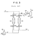
- Fig. 3 shows a conventional two-adsorbing column type apparatus for dehydrating a liquid hydrocarbon with molecular sieves.
- a liquid to be dried 01 is introduced into one of adsorbing columns 02, 03 packed with the molecular sieve which is now performing an adsorbing operation, and water in the liquid to be dehydrated is adsorbed by the molecular sieve and the dehydrated liquid 04 is taken out of the system.
- the recovery operation of the molecular sieve is carried out.
- the molecular sieve on which water is adsorbed are recovered by a high-temperature gas.
- a gas 05 for recovering the molecular sieve is heated up to a level of about 250 to about 300°C in a recovery gas heating furnace 06, and a heated gas for recovery 07 is then forwarded to the adsorbing column in which the recovery operation of the molecular sieve is performed.
- a gas 08 by which the molecular sieve have been recovered is afterwards cooled to ordinary temperatures or so by means of a cooling device 09. This cooled gas 08 is then forwarded to a gas/liquid separator 012, in which water is removed therefrom, and the gas 014 is then discharged from the system.
- switching valves 015 to 022 are disposed, as shown in Fig. 3. These valves are controllable to perform the above-mentioned operation.
- a different process has been disclosed in the DE-A-28 39 432 for the dehydrating of gaseous mixtures containing condensable hydrocarbon.
- the gaseous mixture comprising predominantly hydrocarbons having 1 to 3 carbon atoms, is fed to a washing column at the bottom thereof and a washing liquid, preferably glycol, is introduced at the head of the washing column.
- a washing liquid preferably glycol
- the DE-A-28 29 432 discloses that the glycol adsorbs the water contained in the gaseous mixture, that the hydrocarbons condensed during the washing process are separated from the glycol charged with water and that the charged glycol may be regenerated. According to the DE-A-28 29 432 efforts are emphasized to minimize losses of washing glycol.
- the water content of the hydrocarbon mixture is reduced from 3400 ppm to some few ppm.
- 9000 kg/h triethylene glycol have to be introduced into the washing column in order to dehydrate 160 000 kg/h of gas mixture.
- An object of the present invention is to provide an apparatus and process for dehydrating a liquid by which the above-mentioned problems of conventional ones can be solved.
- the apparatus for dehydrating a liquid of the present invention is constituted as follows:
- the liquid to be dehydrated containing water is mixed with the liquid dehydrating agent in the mixer, whereby water present in the liquid to be dehydrated is absorbed by the liquid dehydrating agent.
- a mixture of the liquid from which water has been removed by the absorption of the liquid dehydrating agent and the liquid dehydrating agent containing the absorbed water is forwarded to the separator, and these liquids are separated from each other therein. Afterward, the dehydrated liquid is taken out of the system.
- the liquid dehydrating agent containing the absorbed water is forwarded to the recovery device, and water is then removed therefrom in this device. Afterward, the water-free dehydrating agent is returned to the mixer and is then used again.
- the liquid to be dehydrated can be dehydrated by the successive fluid operations of the simple apparatus, and furthermore, the apparatus of the present case is simplified and the operation of the apparatus can be facilitated.
- the gas for recovery used in the recovery device regarding the present invention can fulfil its role in a small amount, and a large amount of a heat source is unnecessary.
- the plural sections each comprising the mixer and the separator are arranged in series in the apparatus for dehydrating a liquid described in the above paragraph (1), and therefore the liquid to be dehydrated can be dehydrated sufficiently.
- the liquid dehydrating agent by which water in the liquid to be dehydrated having a lower water content has been absorbed on the downstream side, is fed to the mixer on the upstream side, so that water in the liquid to be dehydrated having a higher water content is absorbed by the fed liquid dehydrating agent.
- the liquid dehydrating agent can be effectively used, and the dehydrating of the liquid to be dehydrated can be achieved efficiently.
- Reference numeral 1 is a liquid to be dehydrated such as a liquid hydrocarbon containing water
- numeral 2 is a mixer to which the liquid to be dehydrated is fed.
- a recovered liquid dehydrating agent 4 is delivered from a recovery device 8 for the liquid dehydrating agent.
- a mixture 3 is forwarded to a liquid/liquid separator 5, where the dehydrated liquid 6 and the liquid dehydrating agent 7 containing the absorbed water are then separated from each other.
- the dehydrated liquid 6 is taken out from the system, and the liquid dehydrating agent 7 containing the absorbed water is fed to the recovery device 8.
- liquid/liquid separator 5 there is used any of a separator in which a difference between gravities is utilized, a parallel plate separator packed with plate-shaped contents, a corrugated plate separator, a cohesion separator called a coalescer , a cohesion separator in which electrodes are used, and a combination thereof.
- the recovery device 8 there is used a device called a dehydrator which is used to remove moisture from a gas.
- the liquid to be dehydrated 1 containing water is mixed with the liquid dehydrating agent 4 in the mixer, so that water present in the liquid to be dehydrated 1 is absorbed by the liquid dehydrating agent.
- the mixture 3 of the liquid to be dehydrated from which water has been removed by the absorption of the liquid dehydrating agent and the liquid dehydrating agent containing the absorbed water is then forwarded to the liquid/liquid separator 5, and these liquids are separated to each other therein.
- the dehydrated liquid 6 is taken out from the system, and on the other hand, the liquid dehydrating agent 7 containing the absorbed water is forwarded to a liquid dehydrating agent recovery device 8.
- water 9 is removed from the liquid dehydrating agent 7 containing the absorbed water so as to recover the liquid dehydrating agent, and the thus recovered liquid dehydrating agent is delivered to the mixer 2 again.
- the liquid to be dehydrated 1 containing water is mixed with the liquid dehydrating agent in the mixer 2, so that water is removed from the liquid to be dehydrated.
- the water-free liquid is then taken out from the system, and simultaneously the liquid dehydrating agent containing the absorbed water is recovered in the liquid dehydrating agent recovery device 8 and is then recycled.
- liquid dehydrating agent examples include triethylene glycol, diethylene glycol, monoethylene glycol, tetraethylene glycol and glycerol.
- triethylene glycol is used as the liquid dehydrating agent, and a mixture of propane and butane is used as the liquid to be dried.
- the conditions and results of the embodiment are set forth in Table 1.
- the liquid to be dehydrated (a mixture of 50 mole percent of liquid propane, 20 mole percent of liquid normal butane and 30 mole percent of liquid isobutane) containing 360 ppm by weight of water (dissolved water and free water) at a flow rate of 100,000 kg/hour is mixed suffiently with the liquid dehydrating agent (triethylene glycol) having a purity of 99.90% by weight at a flow rate of 2,000 kg/hour, whereby water present in the liquid to be dehydrated is absorbed by the liquid dehydrating agent.
- the liquid dehydrating agent triethylene glycol
- the liquid to be dehydrated and the liquid dehydrating agent in the resulting mixture are separated from each other by means of the liquid/liquid separator 5 composed of a gravity difference type separator and a cohesion separator called a coalescer, and the dehydrated liquid 6 is then taken out from the system.
- a water content in the dehydrated liquid 6 is 20 ppm by weight.
- the liquid dehydrating agent 7 containing the dehydrated water is forwarded to the liquid dehydrating agent recovery device 8, where the water 9 is then removed therefrom.
- the recovery of the liquid dehydrating agent is carried out until its purity has reached 99.90% by weight.
- the liquid dehydrating agent recovery device 8 is composed of the following members: A flush separator, a reboiler, a still column, a stripping column, a surge tank, a filter, an active carbon filter, a heat exchanger, a cooler and a pump.
- the liquid dehydrating agent 4 from which water has been removed is delivered to the mixer 2 and is then mixed with the liquid to be dehydrated 1 again.
- a first section comprising the mixer 2 and the liquid/liquid separator 5 and a second section comprising a mixer 2' and a liquid/liquid separator 5', which are the same as in first embodiment, are arranged in series in the form of 2 steps.
- a liquid to be dehydrated containing water is fed to the mixer 2 in the first step section, and the liquid dehydrating agent 13 separated in the liquid/liquid separator 5' in the second section is also fed to the mixer 2 by means of a circulating pump 14.
- the liquid to be dehydrated 6 which has been separated in the liquid/liquid separator 5 is then fed to the mixer 2' in the second section, and the liquid dehydrating agent 7 containing the absorbed water is fed to the liquid dehydrating agent recovery device 8.
- the recovered liquid dehydrating agent 9 is delivered from the liquid dehydrating agent recovery device 8 to the mixer 2' in the second section. Furthermore, the liquid to be dehydrated 12 separated in the liquid/liquid separator 5' in the second section is then taken out from the system, and the liquid dehydrating agent 13 is returned to the mixer 2 in the first section by means of the circulating pump 14.
- the liquid to be dehydrated 1 is mixed, in the mixer 2 of the first section, with the liquid dehydrating agent 13 separated from the liquid/liquid separator 5' in the second section, whereby water present in the liquid to be dehydrated is absorbed by the liquid dehydrating agent.
- a mixture 4 of the liquid to be dehydrated and the liquid dehydrating agent is introduced into the liquid/liquid separator 5, where the dehydrated liquid 6 is then separated from the liquid dehydrating agent 7 containing the absorbed water, and the latter 7 is forwarded to the liquid dehydrating agent recovery device 8.
- the liquid to be dehydrated 6 separated in the liquid/liquid separator 5 and the liquid dehydrating agent 9 recovered in the liquid dehydrating agent recovery device 8 are fed to the mixer 2' in the second section.
- this mixer 2' they are mixed, so that water in the liquid to be dehydrated is absorbed by the liquid dehydrating agent in order to further dehydrate the liquid, and the mixture is then forwarded to the liquid/liquid separator 5' in the second section, where the liquid to be dehydrated is then separated from the liquid dehydrating agent.
- the dehydrated liquid 12 is taken out from the system, and the liquid dehydrating agent 13 separated in the liquid/liquid separator 5' is delivered to the mixer 2 in the first section by means of the liquid dehydrating agent circulating pump 14.
- the water 16 removed from the liquid dehydrating agent in the liquid dehydrating agent recovery device 15 is discharged from the system.
- this embodiment permits dehydrating the liquid to be dehydrated sufficiently in the two steps, and also permits using the liquid dehydrating agent 13 effectively, because the liquid dehydrating agent 13 absorbs, in the mixer 2' in the second section, water in the liquid to be dehydrated 6 having a lower water content from which water has already roughly removed in the mixer 2 in the first section, and the agent 13 is then separated in the liquid/liquid separator 5' in the second section and is afterward forwarded to the mixer 2 in the first section.
- liquid dehydrating agent the same compounds as enumerated in the first embodiment can be used.
- the liquid to be dehydrated (a mixture of 50 mole percent of liquid propane, 20 mole percent of liquid normal butane and 30 mole percent of liquid isobutane) containing 360 ppm by weight of water (dissolved water and free water) at a flow rate of 100,000 kg/hour is mixed with the liquid dehydrating agent 13 separated in the liquid/liquid separator 5' in the second section and then forwarded by the liquid dehydrating agent circulating pump 14, whereby water present in the liquid to be dehydrated 1 is absorbed by the liquid drying agent 13.
- the liquid to be dehydrated a mixture of 50 mole percent of liquid propane, 20 mole percent of liquid normal butane and 30 mole percent of liquid isobutane
- the liquid to be dehydrated and the liquid dehydrating agent in the resulting mixture are separated from each other by means of the liquid/liquid separator 5 composed of a gravity difference type separator and a cohesion separator called a coalescer, and the liquid to be dehydrated 6 is further mixed with the recovered liquid dehydrating agent 9 having a purity of 99.90% by weight in the mixer 2' in the second section.
- the liquid dehydrating agent 7 containing the absorbed water which has been separated in the liquid/liquid separator 5 in the first section is forwarded to the liquid dehydrating agent recovery device 8, where the agent 7 is then recovered up to a purity of 99.90% by weight.
- the liquid to be dehydrated is further dehydrated by the recovered liquid dehydrating agent in the mixer 2' in the second section and is then separated from the liquid dehydrating agent in the liquid/liquid separator 5' in the second section which is the same as the liquid/liquid separator in the first section.
- the thus separated water-free liquid is taken out from the system.
- a water content in the dried liquid 12 is 10 ppm by weight.
- the liquid dehydrating agent separated in the liquid/liquid separator 5' in the second section is then delivered to the mixer 2 in the first section by means of the liquid dehydrating agent circulating pump 14.
- the two sections each comprising the mixer and the liquid/liquid separator are arranged, but three or more of the similar sections may be disposed so that the liquid dehydrating agent separated from the separator in the downstream section may be fed to the mixer in the upstream section.
Description
- The present invention relates to an apparatus for dehydrating a liquid such as a liquid hydrocarbon or the like which is produced in a natural gas treatment plant, a natural gas pressure feed plant, a petroleum refining plant, a petroleum chemical plant or the like.
- Heretofore, the dehydrating of the liquid hydrocarbon has usually been carried out by adsorbing water present in the liquid hydrocarbon with molecular sieves.
- Fig. 3 shows a conventional two-adsorbing column type apparatus for dehydrating a liquid hydrocarbon with molecular sieves.
- As exhibited in this drawing, a liquid to be dried 01 is introduced into one of
adsorbing columns dehydrated liquid 04 is taken out of the system. At this time, in the other adsorbing column, the recovery operation of the molecular sieve is carried out. - The molecular sieve on which water is adsorbed are recovered by a high-temperature gas. A
gas 05 for recovering the molecular sieve is heated up to a level of about 250 to about 300°C in a recoverygas heating furnace 06, and a heated gas forrecovery 07 is then forwarded to the adsorbing column in which the recovery operation of the molecular sieve is performed. Agas 08 by which the molecular sieve have been recovered is afterwards cooled to ordinary temperatures or so by means of acooling device 09. This cooledgas 08 is then forwarded to a gas/liquid separator 012, in which water is removed therefrom, and the gas 014 is then discharged from the system. - On pipes for the liquid to be dried 01, the dried
liquid 04, the gas forrecovery 05 and thegas 08 by which the molecular sieve have been recovered, switching valves 015 to 022 are disposed, as shown in Fig. 3. These valves are controllable to perform the above-mentioned operation. - In the
adsorbing columns
Adsorption - discharge of a liquid - reduction in pressure - heating - cooling - application of pressure - charge of a liquid - waiting. - However, the conventional apparatus for drying the liquid, in which the molecular sieve and the like are utilized, has the following drawbacks:
- (1) To recover the dehydrating agent by which water has been adsorbed, a great deal of gas is necessary. When the gas by which the dehydrating agent has been recovered cannot be reused, this gas is discarded in vain.
- (2) For the heating of the gas for recovery, a large amount of heat source is required.
- (3) In the adsorbing columns, the operations of the adsorption and recovery must be carried out alternately. In consequence, many switching valves and pipes are required, as shown in Fig. 3, and thus the operations of using these valves are complex and troublesome.
- A different process has been disclosed in the DE-A-28 39 432 for the dehydrating of gaseous mixtures containing condensable hydrocarbon. The gaseous mixture comprising predominantly hydrocarbons having 1 to 3 carbon atoms, is fed to a washing column at the bottom thereof and a washing liquid, preferably glycol, is introduced at the head of the washing column. Furthermore the DE-A-28 29 432 discloses that the glycol adsorbs the water contained in the gaseous mixture, that the hydrocarbons condensed during the washing process are separated from the glycol charged with water and that the charged glycol may be regenerated. According to the DE-A-28 29 432 efforts are emphasized to minimize losses of washing glycol. In the embodiment according to the example of the DE-A-28 29 432 the water content of the hydrocarbon mixture is reduced from 3400 ppm to some few ppm. However, to achieve this goal 9000 kg/h triethylene glycol have to be introduced into the washing column in order to dehydrate 160 000 kg/h of gas mixture.
- An object of the present invention is to provide an apparatus and process for dehydrating a liquid by which the above-mentioned problems of conventional ones can be solved.
- For the purpose of solving the above-mentioned problems, the apparatus for dehydrating a liquid of the present invention is constituted as follows:
- (1) The apparatus of the present invention is equipped with a mixer for mixing a liquid dehydrating agent with a liquid to be dehydrated, a separator for separating the liquid dehydrating agent and the liquid to be dehydrated in a mixture thereof from each other, a recovery device for recovering the separated liquid dehydrating agent which has been forwarded from the separator, and a feed device for feeding the recovered liquid drying agent to the mixer, wherein the separator is arranged so that the mixture is forwarded from the mixer to the separator and wherein the separator is a separator in which a difference between gravities is utilized.
- (2) Furthermore, in the apparatus for dehydrating a liquid referred to in the above paragraph (1), a plurality of sections each comprising the mixer and the separator are arranged in series so that the liquid dehydrating agent separated in the separator on the downstream side may be fed to the mixer on the upstream side.
- According to a process of the present invention in the apparatus of the present invention described in the above paragraph (1), the liquid to be dehydrated containing water is mixed with the liquid dehydrating agent in the mixer, whereby water present in the liquid to be dehydrated is absorbed by the liquid dehydrating agent.
- A mixture of the liquid from which water has been removed by the absorption of the liquid dehydrating agent and the liquid dehydrating agent containing the absorbed water is forwarded to the separator, and these liquids are separated from each other therein. Afterward, the dehydrated liquid is taken out of the system.
- On the other hand, the liquid dehydrating agent containing the absorbed water is forwarded to the recovery device, and water is then removed therefrom in this device. Afterward, the water-free dehydrating agent is returned to the mixer and is then used again.
- According to the present invention, the liquid to be dehydrated can be dehydrated by the successive fluid operations of the simple apparatus, and furthermore, the apparatus of the present case is simplified and the operation of the apparatus can be facilitated. In addition, the gas for recovery used in the recovery device regarding the present invention can fulfil its role in a small amount, and a large amount of a heat source is unnecessary.
- According to the constitution described in the above paragraph (2) of the present invention, the plural sections each comprising the mixer and the separator are arranged in series in the apparatus for dehydrating a liquid described in the above paragraph (1), and therefore the liquid to be dehydrated can be dehydrated sufficiently. In addition, the liquid dehydrating agent, by which water in the liquid to be dehydrated having a lower water content has been absorbed on the downstream side, is fed to the mixer on the upstream side, so that water in the liquid to be dehydrated having a higher water content is absorbed by the fed liquid dehydrating agent. In consequence, the liquid dehydrating agent can be effectively used, and the dehydrating of the liquid to be dehydrated can be achieved efficiently.
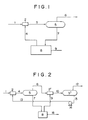
- Fig. 1 is a system diagram of a first embodiment of the present invention,
- Fig. 2 is a system diagram of a second embodiment of the present invention, and
- Fig. 3 is a system diagram of a conventional liquid-drying apparatus in which molecular sieves are used.
- A first embodiment of the present invention will be described in reference to Fig. 1.
- Reference numeral 1 is a liquid to be dehydrated such as a liquid hydrocarbon containing water, and
numeral 2 is a mixer to which the liquid to be dehydrated is fed. To themixer 2, a recoveredliquid dehydrating agent 4 is delivered from arecovery device 8 for the liquid dehydrating agent. Amixture 3 is forwarded to a liquid/liquid separator 5, where thedehydrated liquid 6 and theliquid dehydrating agent 7 containing the absorbed water are then separated from each other. Thedehydrated liquid 6 is taken out from the system, and theliquid dehydrating agent 7 containing the absorbed water is fed to therecovery device 8. - As the above-mentioned
mixer 2, there is used any of a liquid/liquid mixing valve, a static mixer, a liquid/liquid mixing nozzle and a combination thereof. - As the above-mentioned liquid/
liquid separator 5, there is used any of a separator in which a difference between gravities is utilized, a parallel plate separator packed with plate-shaped contents, a corrugated plate separator, a cohesion separator called a coalescer , a cohesion separator in which electrodes are used, and a combination thereof. - Furthermore, as the
recovery device 8, there is used a device called a dehydrator which is used to remove moisture from a gas. - In this embodiment, the liquid to be dehydrated 1 containing water is mixed with the
liquid dehydrating agent 4 in the mixer, so that water present in the liquid to be dehydrated 1 is absorbed by the liquid dehydrating agent. - The
mixture 3 of the liquid to be dehydrated from which water has been removed by the absorption of the liquid dehydrating agent and the liquid dehydrating agent containing the absorbed water is then forwarded to the liquid/liquid separator 5, and these liquids are separated to each other therein. Thedehydrated liquid 6 is taken out from the system, and on the other hand, theliquid dehydrating agent 7 containing the absorbed water is forwarded to a liquid dehydratingagent recovery device 8. - In the
recovery device 8,water 9 is removed from theliquid dehydrating agent 7 containing the absorbed water so as to recover the liquid dehydrating agent, and the thus recovered liquid dehydrating agent is delivered to themixer 2 again. - In this way, the liquid to be dehydrated 1 containing water is mixed with the liquid dehydrating agent in the
mixer 2, so that water is removed from the liquid to be dehydrated. The water-free liquid is then taken out from the system, and simultaneously the liquid dehydrating agent containing the absorbed water is recovered in the liquid dehydratingagent recovery device 8 and is then recycled. - Examples of the liquid dehydrating agent used in this emobodiment include triethylene glycol, diethylene glycol, monoethylene glycol, tetraethylene glycol and glycerol.
- In this embodiment, triethylene glycol is used as the liquid dehydrating agent, and a mixture of propane and butane is used as the liquid to be dried. The conditions and results of the embodiment are set forth in Table 1.
- In the
mixer 2 composed of a liquid/liquid mixing nozzle and a liquid/liquid mixing valve, the liquid to be dehydrated (a mixture of 50 mole percent of liquid propane, 20 mole percent of liquid normal butane and 30 mole percent of liquid isobutane) containing 360 ppm by weight of water (dissolved water and free water) at a flow rate of 100,000 kg/hour is mixed suffiently with the liquid dehydrating agent (triethylene glycol) having a purity of 99.90% by weight at a flow rate of 2,000 kg/hour, whereby water present in the liquid to be dehydrated is absorbed by the liquid dehydrating agent. - The liquid to be dehydrated and the liquid dehydrating agent in the resulting mixture are separated from each other by means of the liquid/
liquid separator 5 composed of a gravity difference type separator and a cohesion separator called a coalescer, and thedehydrated liquid 6 is then taken out from the system. In this case, a water content in thedehydrated liquid 6 is 20 ppm by weight. - On the other hand, the
liquid dehydrating agent 7 containing the dehydrated water is forwarded to the liquid dehydratingagent recovery device 8, where thewater 9 is then removed therefrom. In this case, the recovery of the liquid dehydrating agent is carried out until its purity has reached 99.90% by weight. - The liquid dehydrating
agent recovery device 8 is composed of the following members:
A flush separator, a reboiler, a still column, a stripping column, a surge tank, a filter, an active carbon filter, a heat exchanger, a cooler and a pump. - The
liquid dehydrating agent 4 from which water has been removed is delivered to themixer 2 and is then mixed with the liquid to be dehydrated 1 again.
- A second embodiment of the present invention will be described in reference to Fig. 2.
- In this embodiment, a first section comprising the
mixer 2 and the liquid/liquid separator 5 and a second section comprising a mixer 2' and a liquid/liquid separator 5', which are the same as in first embodiment, are arranged in series in the form of 2 steps. A liquid to be dehydrated containing water is fed to themixer 2 in the first step section, and theliquid dehydrating agent 13 separated in the liquid/liquid separator 5' in the second section is also fed to themixer 2 by means of a circulatingpump 14. The liquid to be dehydrated 6 which has been separated in the liquid/liquid separator 5 is then fed to the mixer 2' in the second section, and theliquid dehydrating agent 7 containing the absorbed water is fed to the liquid dehydratingagent recovery device 8. The recoveredliquid dehydrating agent 9 is delivered from the liquid dehydratingagent recovery device 8 to the mixer 2' in the second section. Furthermore, the liquid to be dehydrated 12 separated in the liquid/liquid separator 5' in the second section is then taken out from the system, and theliquid dehydrating agent 13 is returned to themixer 2 in the first section by means of the circulatingpump 14. - In this embodiment, the liquid to be dehydrated 1 is mixed, in the
mixer 2 of the first section, with theliquid dehydrating agent 13 separated from the liquid/liquid separator 5' in the second section, whereby water present in the liquid to be dehydrated is absorbed by the liquid dehydrating agent. Amixture 4 of the liquid to be dehydrated and the liquid dehydrating agent is introduced into the liquid/liquid separator 5, where thedehydrated liquid 6 is then separated from theliquid dehydrating agent 7 containing the absorbed water, and the latter 7 is forwarded to the liquid dehydratingagent recovery device 8. The liquid to be dehydrated 6 separated in the liquid/liquid separator 5 and theliquid dehydrating agent 9 recovered in the liquid dehydratingagent recovery device 8 are fed to the mixer 2' in the second section. In this mixer 2', they are mixed, so that water in the liquid to be dehydrated is absorbed by the liquid dehydrating agent in order to further dehydrate the liquid, and the mixture is then forwarded to the liquid/liquid separator 5' in the second section, where the liquid to be dehydrated is then separated from the liquid dehydrating agent. Thedehydrated liquid 12 is taken out from the system, and theliquid dehydrating agent 13 separated in the liquid/liquid separator 5' is delivered to themixer 2 in the first section by means of the liquid dehydratingagent circulating pump 14. Thewater 16 removed from the liquid dehydrating agent in the liquid dehydrating agent recovery device 15 is discharged from the system. - As understood from the above, this embodiment permits dehydrating the liquid to be dehydrated sufficiently in the two steps, and also permits using the
liquid dehydrating agent 13 effectively, because theliquid dehydrating agent 13 absorbs, in the mixer 2' in the second section, water in the liquid to be dehydrated 6 having a lower water content from which water has already roughly removed in themixer 2 in the first section, and theagent 13 is then separated in the liquid/liquid separator 5' in the second section and is afterward forwarded to themixer 2 in the first section. - Also in this embodiment, as the liquid dehydrating agent, the same compounds as enumerated in the first embodiment can be used.
- In this embodiment, a mixture of propane and butane which is the liquid to be dehydrated is dehydrated by the use of triethylene glycol as the liquid dehydrating agent, and the conditions and results of this embodiment are set forth in Table 2.
- In the
mixer 2 in the first step composed of a liquid/liquid mixing nozzle and a liquid/liquid mixing valve, the liquid to be dehydrated (a mixture of 50 mole percent of liquid propane, 20 mole percent of liquid normal butane and 30 mole percent of liquid isobutane) containing 360 ppm by weight of water (dissolved water and free water) at a flow rate of 100,000 kg/hour is mixed with theliquid dehydrating agent 13 separated in the liquid/liquid separator 5' in the second section and then forwarded by the liquid dehydratingagent circulating pump 14, whereby water present in the liquid to be dehydrated 1 is absorbed by theliquid drying agent 13. - The liquid to be dehydrated and the liquid dehydrating agent in the resulting mixture are separated from each other by means of the liquid/
liquid separator 5 composed of a gravity difference type separator and a cohesion separator called a coalescer, and the liquid to be dehydrated 6 is further mixed with the recoveredliquid dehydrating agent 9 having a purity of 99.90% by weight in the mixer 2' in the second section. Theliquid dehydrating agent 7 containing the absorbed water which has been separated in the liquid/liquid separator 5 in the first section is forwarded to the liquid dehydratingagent recovery device 8, where theagent 7 is then recovered up to a purity of 99.90% by weight. - The liquid to be dehydrated is further dehydrated by the recovered liquid dehydrating agent in the mixer 2' in the second section and is then separated from the liquid dehydrating agent in the liquid/liquid separator 5' in the second section which is the same as the liquid/liquid separator in the first section. The thus separated water-free liquid is taken out from the system. In this case, a water content in the dried
liquid 12 is 10 ppm by weight. - The liquid dehydrating agent separated in the liquid/liquid separator 5' in the second section is then delivered to the
mixer 2 in the first section by means of the liquid dehydratingagent circulating pump 14.
- In Fig. 3, comparisons are made between amounts of the used recovery gas and the consumed fuel gas in the first embodiment, the second embodiment and a conventional dehydrating apparatus in which molecular sieves are used.
- (1) Comparison between amounts of the used recovery gas:
As exhibited in Table 3, in the case that the molecular sieves are used, 5,600 normal m³/hour of the gas is necessary to recover the molecular sieves, whereas in the cases of the first and second embodiments, 45 normal m³/hour of the gas for the recovery of the liquid dehydrating agent is only required. - (2) Comparison between amounts of the consumed fuel gas:
As exhibited in Table 3, in the case that the molecular sieves are used, 130 normal m³/hour of the fuel gas is consumed, whereas in the liquid dehydrating agent recovery device of the first and second embodiments, 13 normal m³/hour of the fuel gas is only required. - (3) Also with regard to consumed amounts of cooling water, mechanical power and the dehydrating agent, a comparison is made in Table 3.
- The results in Table 3 indicate that the first and second embodiments permit remarkably reducing the amounts of the recovery gas and the fuel gas used in the liquid dehydrating agent recovery device, as compared with the conventional case in which the molecular sieves are used.
- In the second embodiment described above, the two sections each comprising the mixer and the liquid/liquid separator are arranged, but three or more of the similar sections may be disposed so that the liquid dehydrating agent separated from the separator in the downstream section may be fed to the mixer in the upstream section.


Claims (7)
- A process for dehydrating a body of liquid, characterized in that a liquid dehydrating agent (4) and a liquid to be dehydrated (1) are mixed in a mixer (2) so as to cause the water part of the liquid (1) to be absorbed by the liquid dehydrating agent (4), then the liquid (3) freed from water part and the liquid dehydrating agent (7) having absorbed the water part are separated from each other in a separator (5) and subsequently the separated liquid dehydrating agent (7) is recovered by the recovery device (8) so that the recovered liquid dehydrating agent (4) can be used by recirculation as a liquid dehydrating agent (4) for supply to the mixer (2).
- A process according to claim 1, characterized in that two stages, each having a mixer (2, 2') and a separator (5, 5') are arranged in series, so that the liquid dehydrating agent (13) separated by the separator (5') at the second section is supplied to the mixer (2) at the first section and the liquid dehydrating agent (7) separated by separator (5) at the first section is recovered by the recovery device (8) and the liquid dehydrating agent (9) thus recovered is supplied to mixer (2') at the second section, thus dehydrating the liquid (1) in a stepwise manner.
- A process according to claim 1 or 2, characterized in that the liquid dehydrating agent (4, 7, 9, 13) for use is triethylene glycol, diethylene glycol, monoethylene glycol, tetraethylene glycol and/or glycerol.
- An apparatus suitable for carrying out the process of claims 1 to 3 comprising- a mixer (2) for mixing a liquid dehydrating agent (4) with a liquid (1) to be dehydrated,- a separator (5) for separating liquid dehydrating agent (4) and dehydrated liquid (1) in the resulting mixture (3) from each other,- a recovery device (8) for recovering the separated liquid dehydrating agent (7), which has been forwarded from the separator (5), and- a device for feeding the recovered liquid dehydrating agent (4) to mixer (2), which apparatus is characterized in that
the separator (5) is arranged so that mixture (3) is forwarded from mixer (2) to the separator (5) and in that the separator (5) is any of a separator in which a difference between gravities is utilized, a parallel plate separator packed with plate-shaped contents, a corrugated plate separator, a cohesion separator called a coalescer, a cohesion separator in which electrodes are used, and a combination thereof. - The apparatus according to claim 4, characterized in that mixer (2) is any of a liquid/liquid mixing valve, a static mixer, a liquid/liquid mixing nozzle and a combination thereof.
- The apparatus according to any of claim 4 or 5, characterized in that recovery device (8) is a dehydrator which is used to remove moisture from a gas.
- The apparatus according to any of claims 4 to 7, characterized in that plural sections each comprising a mixer (2, 2') and a separator (5, 5') are arranged in series so that the liquid dehydrating agent (13) separated in the separator (5') on a downstream side may be fed to the mixer (2) on an upstream side.
Applications Claiming Priority (2)
| Application Number | Priority Date | Filing Date | Title |
|---|---|---|---|
| JP63263880A JPH07100121B2 (en) | 1988-10-21 | 1988-10-21 | Liquid dryer |
| JP263880/88 | 1988-10-21 |
Publications (3)
| Publication Number | Publication Date |
|---|---|
| EP0364671A2 EP0364671A2 (en) | 1990-04-25 |
| EP0364671A3 EP0364671A3 (en) | 1990-11-28 |
| EP0364671B1 true EP0364671B1 (en) | 1994-01-12 |
Family
ID=17395525
Family Applications (1)
| Application Number | Title | Priority Date | Filing Date |
|---|---|---|---|
| EP89112408A Revoked EP0364671B1 (en) | 1988-10-21 | 1989-07-07 | Apparatus and process for drying liquid |
Country Status (3)
| Country | Link |
|---|---|
| EP (1) | EP0364671B1 (en) |
| JP (1) | JPH07100121B2 (en) |
| DE (1) | DE68912264T2 (en) |
Family Cites Families (6)
| Publication number | Priority date | Publication date | Assignee | Title |
|---|---|---|---|---|
| AT214412B (en) * | 1957-12-12 | 1961-04-10 | Separator Ab | Process for the continuous breaking of emulsions |
| DE2839432C2 (en) * | 1978-09-11 | 1984-06-28 | Linde Ag, 6200 Wiesbaden | Process for drying gases containing condensable hydrocarbons |
| FR2467235A1 (en) * | 1979-10-12 | 1981-04-17 | Petroles Cie Francaise | EQUIPMENT FOR THE RECOVERY AND TREATMENT OF VISCOUS OIL EMULSIONS |
| GB2101900B (en) * | 1981-06-24 | 1985-02-27 | British Petroleum Co Plc | Demulsifying water-in-oil emulsions |
| DE3446688A1 (en) * | 1984-12-21 | 1986-06-26 | Texaco Canada Resources Ltd., Calgary, Alberta | Process and device for dissolving a bitumen-in-water emulsion |
| DK373686A (en) * | 1985-08-12 | 1987-02-13 | Dow Chemical Co | HOSTING PROCEDURES |
-
1988
- 1988-10-21 JP JP63263880A patent/JPH07100121B2/en not_active Expired - Fee Related
-
1989
- 1989-07-07 EP EP89112408A patent/EP0364671B1/en not_active Revoked
- 1989-07-07 DE DE89112408T patent/DE68912264T2/en not_active Revoked
Also Published As
| Publication number | Publication date |
|---|---|
| DE68912264D1 (en) | 1994-02-24 |
| JPH02111406A (en) | 1990-04-24 |
| JPH07100121B2 (en) | 1995-11-01 |
| EP0364671A3 (en) | 1990-11-28 |
| DE68912264T2 (en) | 1994-05-05 |
| EP0364671A2 (en) | 1990-04-25 |
Similar Documents
| Publication | Publication Date | Title |
|---|---|---|
| US5345771A (en) | Process for recovering condensable compounds from inert gas-condensable compound vapor mixtures | |
| US5061465A (en) | Bulk CO2 recovery process | |
| US4270938A (en) | Processes for decontaminating nuclear process off-gas streams | |
| EP0046472B1 (en) | Process and apparatus for recovering hydrocarbons from air-hydrocarbon vapor mixtures | |
| CN1946632B (en) | Hydrogen sulfide is converted into the method and apparatus of hydrogen and sulphur | |
| US6183540B1 (en) | Method and apparatus for removing aromatic hydrocarbons from a gas stream prior to an amine-based gas sweetening process | |
| US5520724A (en) | Process for the recovery of low molecular weight C2+ hydrocarbons from a cracking gas | |
| CA2162575A1 (en) | Controlling emissions from glycol dehydrators | |
| JPH119940A (en) | Method for separating liquefied hydrocarbon from condensable hydrocarbon-containing gas | |
| JPH11509891A (en) | Steam recovery system | |
| CN202516336U (en) | Storage tank area effluent gas treatment system | |
| EP2559466A1 (en) | Improved extractive distillation processes using water-soluble extractive solvents | |
| US4962238A (en) | Removal of glycols from a polyalkylene glycol dialkyl ether solution | |
| US4101297A (en) | Process for recovering a solvent vapor | |
| US8540803B2 (en) | Method and device for removing water from natural gas or from industrial gases with physical solvents | |
| JPS5827961B2 (en) | Method for rectifying distillable mixtures | |
| EP0567388B1 (en) | A process for separating a volatile organic compound from a gas | |
| US5766423A (en) | Dehydration of gases with liquid desiccants | |
| US3831348A (en) | Removal of sulfur compounds from glycolic and alcoholic compounds by solvent extraction | |
| US4227891A (en) | Recovery of hydrocarbon vapors from air | |
| US5315832A (en) | Process for the recovery of a light hydrocarbon fraction from marine loading operations | |
| EP0364671B1 (en) | Apparatus and process for drying liquid | |
| RU2135545C1 (en) | Method and plant for stabilizing natural crude oil on borehole exit | |
| CA1134121A (en) | Vapor recovery | |
| EP0448880B1 (en) | Process and apparatus for recovering hydrocarbons from air-hydrocarbon vapor mixtures |
Legal Events
| Date | Code | Title | Description |
|---|---|---|---|
| PUAI | Public reference made under article 153(3) epc to a published international application that has entered the european phase |
Free format text: ORIGINAL CODE: 0009012 |
|
| AK | Designated contracting states |
Kind code of ref document: A2 Designated state(s): DE FR GB IT |
|
| PUAL | Search report despatched |
Free format text: ORIGINAL CODE: 0009013 |
|
| AK | Designated contracting states |
Kind code of ref document: A3 Designated state(s): DE FR GB IT |
|
| 17P | Request for examination filed |
Effective date: 19901212 |
|
| 17Q | First examination report despatched |
Effective date: 19911204 |
|
| GRAA | (expected) grant |
Free format text: ORIGINAL CODE: 0009210 |
|
| AK | Designated contracting states |
Kind code of ref document: B1 Designated state(s): DE FR GB IT |
|
| REF | Corresponds to: |
Ref document number: 68912264 Country of ref document: DE Date of ref document: 19940224 |
|
| ITF | It: translation for a ep patent filed |
Owner name: BUGNION S.P.A. |
|
| ET | Fr: translation filed | ||
| PLBI | Opposition filed |
Free format text: ORIGINAL CODE: 0009260 |
|
| 26 | Opposition filed |
Opponent name: BASF AKTIENGESELLSCHAFT Effective date: 19941012 |
|
| PGFP | Annual fee paid to national office [announced via postgrant information from national office to epo] |
Ref country code: GB Payment date: 19960628 Year of fee payment: 8 |
|
| PGFP | Annual fee paid to national office [announced via postgrant information from national office to epo] |
Ref country code: FR Payment date: 19960709 Year of fee payment: 8 |
|
| RDAH | Patent revoked |
Free format text: ORIGINAL CODE: EPIDOS REVO |
|
| PGFP | Annual fee paid to national office [announced via postgrant information from national office to epo] |
Ref country code: DE Payment date: 19960712 Year of fee payment: 8 |
|
| RDAG | Patent revoked |
Free format text: ORIGINAL CODE: 0009271 |
|
| STAA | Information on the status of an ep patent application or granted ep patent |
Free format text: STATUS: PATENT REVOKED |
|
| GBPR | Gb: patent revoked under art. 102 of the ep convention designating the uk as contracting state |
Free format text: 960725 |
|
| 27W | Patent revoked |
Effective date: 19960725 |
|
| PLAB | Opposition data, opponent's data or that of the opponent's representative modified |
Free format text: ORIGINAL CODE: 0009299OPPO |