EP0364649B1 - A vehicle-seat heating construction - Google Patents
A vehicle-seat heating construction Download PDFInfo
- Publication number
- EP0364649B1 EP0364649B1 EP88850293A EP88850293A EP0364649B1 EP 0364649 B1 EP0364649 B1 EP 0364649B1 EP 88850293 A EP88850293 A EP 88850293A EP 88850293 A EP88850293 A EP 88850293A EP 0364649 B1 EP0364649 B1 EP 0364649B1
- Authority
- EP
- European Patent Office
- Prior art keywords
- vehicle seat
- temperature
- temperature level
- heating
- control
- Prior art date
- Legal status (The legal status is an assumption and is not a legal conclusion. Google has not performed a legal analysis and makes no representation as to the accuracy of the status listed.)
- Expired - Lifetime
Links
Images

Classifications
-
- B—PERFORMING OPERATIONS; TRANSPORTING
- B60—VEHICLES IN GENERAL
- B60N—SEATS SPECIALLY ADAPTED FOR VEHICLES; VEHICLE PASSENGER ACCOMMODATION NOT OTHERWISE PROVIDED FOR
- B60N2/00—Seats specially adapted for vehicles; Arrangement or mounting of seats in vehicles
- B60N2/56—Heating or ventilating devices
- B60N2/5678—Heating or ventilating devices characterised by electrical systems
- B60N2/5685—Resistance
Definitions
- the present invention relates to a vehicle-seat heating construction of the kind set forth in the preamble of Claim 1.
- the thermostat circuit with two temperature regulators which work in parallel so to say, and each of which is set to a respective temperature value.
- One of the thermostat circuits has a higher deactivation or switch-off temperature than the other, but operates only once, so that the vehicle seat temperature will first rise to the high temperature level, before the current is switched off. The temperature will then decrease and when it falls beneath the other set temperature level the current will again be switched on, whereafter the current is repeatedly switched off and on, in a conventional manner, so as to control the temperature to the lower of the two preset temperature levels.
- the higher starting temperature may also be reached with the aid of a time circuit, wherein during the starting process full power is permitted to prevail for a predetermined time period or for a time period which is determined by the temperature of the vehicle seat at the time of starting the heating process, and the temperature is subsequently controlled at a comfortable level when this time period has lapsed.
- the first circuit may be constructed so as to be activated at 19°C and deactivated at 39°C, whereas the other circuit is constructed for activation at 27°C and deactivation at 31°C.
- the first mentioned circuit which is effective in heating the vehicle seat initially, will only begin to generate heat when the temperature of the sitting-part of the vehicle seat is beneath 19°C, which means that the temporary absence of the driver from his seat will not result in the initiation of a new starting sequence as soon as he reseats himself.
- control devices 6 are located at the one edge 5 of the heating plate 4, such as to be protected by the lower edge part of the back-rest 11, as shown in Figure 1 and Figure 2.
- FIG 4 illustrates the construction of the electric circuit.
- the electric heating element 1 illustrated in Figure 4 may also include the electric heating element 20 of the back-rest, shown in Figure 1, and may be connected either in series or in parallel (not shown).
- the positive and negative terminals of the circuit are connected to the electric current supply source of the vehicle via electric switches not snown, e.g. a manually operated switch having connected in series therewith a switch which is operated by the load on the vehicle seat concerned.
- the electrolytic capacitor 40 of 1 uF which is connected between earth and the voltage dividing point for the positive input of the comparator 41.
- the positive input will initially have a lower voltage than the negative input connected to the sensor, so that the comparator will not then become active.
- a prerequisite in this respect is namely that the sensor voltage is lower than the voltage on the positive input.
Description
- The present invention relates to a vehicle-seat heating construction of the kind set forth in the preamble of
Claim 1. - It has been normal practice for many years to provide at least the driving seat of an automotive vehicle and often also the front passenger seat of the vehicle, with electric heating elements which improve passenger comfort and which enable a person to seat himself in a vehicle which has been left standing in cold surroundings without danger to his health. An example of such a known seat heater is shown in De-U-7913491. Other examples are SE-B-8200711-3 and SE-B-8200852-5.
- In the case of these known heated seat structures, there is incorporated in the upholstery of the sitting part and the back-rest part of the vehicle seat a heating element, which, as a rule has the form of a meandering array of metal wires of suitable resistance such as to produce a satisfactory power output when coupled to the electrical system of the vehicle (now normally a 12V system). The power output is often regulated, or capable of being regulated, so as to prevent the temperature from becoming too high.
- The heating element of such seats can be activated through a manually operated switch and, as a rule, through a further switch which is connected in series with the former switch and which detects when a person is sitting in the vehicle seat.
- In addition to heating elements in the seating part and the back-rest of the vehicle seat, and the provision of activation and deactivation switches, an electrically heated vehicle seat will normally require some form of temperature control arrangement which includes a heat sensor for controlling the current supply. In this regard, many different systems are known to the art, such as systems incorporating bimetal sensors, relays etc., and such control systems have either been mounted in the actual vehicle seat itself or, for instance, on the instrument panel of the vehicle.
- The general object of this invention is to provide a vehicle seat heating construction for vehicles which can be fitted as easily as possible and which further is suitable to practical conditions in a cold climate.
- This general object is achieved with a vehicle seat construction of the aforesaid kind having the features set out in the characterizing clause of
Claim 1. - Because the temperature sensor, which is thus located in a favorable position, detects temperature directly, it is possible to take into account, in a particularly practical manner, the heat required, not only with regard to the final temperature necessary for the seated vehicle occupant to be comfortably warmed, but also the temperature of the person seated in the seat. A person who enters the vehicle from extremely cold surroundings will have clothes which are both thick and heavily chilled. Consequently, it must be possible to be able to produce initially a very powerful output which is much higher than that subsequently required.
- This is achieved in accordance with the invention, by providing the thermostat circuit with two temperature regulators which work in parallel so to say, and each of which is set to a respective temperature value. One of the thermostat circuits has a higher deactivation or switch-off temperature than the other, but operates only once, so that the vehicle seat temperature will first rise to the high temperature level, before the current is switched off. The temperature will then decrease and when it falls beneath the other set temperature level the current will again be switched on, whereafter the current is repeatedly switched off and on, in a conventional manner, so as to control the temperature to the lower of the two preset temperature levels.
- Suitable switch-off temperatures for the aforesaid two cases are, e.g., 39°C and 29°C. In this respect it is preferred that the nominal power output of the heating element used is greater than that of prior art constructions, so that the desired temperature is reached quickly, the inventive vehicle-heating construction being such as to enable such high power outputs to be achieved. A suitable power output is 120 Watts per vehicle seat. Because the higher power output is actually only required as an initial or starting output, the heating element may also be incorporated in a two-circuit system, which circuits are initially connected in parallel during the initial heating process and then in series. In this case, the two heating resistor elements may be arranged respectively for the sitting-part and the back-rest part of the vehicle seat. In view of the fact that more power is consumed in the sitting-part of the seat than the back-rest part thereof, it may be expedient to place part of one thermal resistor element in the back-rest part and part in the sitting-part of the seat, wherein the resistor elements may also be given the same resistance value.
- The higher starting temperature may also be reached with the aid of a time circuit, wherein during the starting process full power is permitted to prevail for a predetermined time period or for a time period which is determined by the temperature of the vehicle seat at the time of starting the heating process, and the temperature is subsequently controlled at a comfortable level when this time period has lapsed.
- In this respect it is preferred to make the high power function contingent on the starting temperature, in view of the fact that the vehicle seat is not necessarily cold at the time of starting the seat-heating process, but that the heating process is initiated due to the fact that the driver, for instance, has left the vehicle temporarily and has then returned to the vehicle, in which case it is unnecessary to subject the driver to excessive temperatures.
- This advantage is afforded by the provision of two separate control circuits which are constructed for deactivation at mutually different temperatures and which have mutually different "hysteresis actions". For example, the first circuit may be constructed so as to be activated at 19°C and deactivated at 39°C, whereas the other circuit is constructed for activation at 27°C and deactivation at 31°C. Thus, the first mentioned circuit, which is effective in heating the vehicle seat initially, will only begin to generate heat when the temperature of the sitting-part of the vehicle seat is beneath 19°C, which means that the temporary absence of the driver from his seat will not result in the initiation of a new starting sequence as soon as he reseats himself. The desired effect is achieved, because the activation and deactivation temperatures of the first control circuit form a temperature range of which the temperature range between the activation and deactivation temperatures of the second control circuit form a minor part, and because the circuit activation signals are added with logic AND-operation to the current controlling element, and also because at least the first control circuit is constructed so as not to be activated at temperatures within its individual hysteresis interval when it is made current conducting, by seat pressure contact.
- According to the embodiments of the invention, it is also an object to provide a vehicle seat heating construction which can be fitted as easily as possible and with which the control components can be combined together with the actual heating element itself to the best extent possible, so as to form a composite component which need only be coupled to the battery voltage of the vehicle in order to be heat-controlling. A related object is to provide such a composite component which can be fitted into a vehicle seat during the manufacture thereof and which will continue to function satisfactorily despite the repeated strain to which the vehicle seat is subjected as people climb into and out of the seat, shift position in the seat, or when children climb and jump on the seat, etc. Such further objects may be attained when the invention is realized according to further embodiments thereof.
- The invention will now be described with reference to non-limiting exemplifying embodiments illustrated in the accompanying drawings.
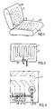
- Figure 1 is a schematic illustration of av vehicle seat.
- Figure 2 illustrates a component with integrated heating element, sensor and control means.
- Figure 3 is a detailed view of components according to Figure 2.
- Figure 4 is a circuit diagram.
- Figure 1 illustrates schematically a vehicle seat comprising a sitting-
part 10 and a back-rest 11. The sitting-part 10 extends beneath the upholstery of the back-rest in a quite conventional manner. Heating elements illustrated schematically at 1 are placed beneath the coverings of both the sittingpart 10 and the back-rest 11 of the vehicle seat. As is conventional in such constructions, the heating elements include wire loops laid in a meandering pattern and attached to a support, e.g. made of polyether foam, said elements being fitted to respective vehicle seats during their manufacture. The heating elements or plates are normally in the form of laminates comprising a covering of fabric or like material on mutually opposite sides of a thin sheet of foamed plastic, the resistance wires being placed beneath the fabric covering on the upwardly facing side. - In the case of the present inventive arrangement, substantially all control devices 6 are located at the one
edge 5 of the heating plate 4, such as to be protected by the lower edge part of the back-rest 11, as shown in Figure 1 and Figure 2. - It will be seen from the part view of Figure 3 that the control device 6, here on a small circuit board or card (22 × 44 mm) with surface mounted components, is placed at the
edge 5, with the sensor 2, an NTC-resistor, located on one side, close to a resistance wire and attached by means of a heat melt adhesive. Acurrent supply cable 9 has three conductors, which enables a connection to be established with the electric current-source of the vehicle and also with theheating element 20 of the back-rest 11 (Figure 1), such that the same control members will control the supply of current thereto. The circuit card, or board, is placed in a fabric pocket 7 sewn with the aid ofseams 8. - Figure 4 illustrates the construction of the electric circuit. The
electric heating element 1 illustrated in Figure 4 may also include theelectric heating element 20 of the back-rest, shown in Figure 1, and may be connected either in series or in parallel (not shown). The positive and negative terminals of the circuit are connected to the electric current supply source of the vehicle via electric switches not snown, e.g. a manually operated switch having connected in series therewith a switch which is operated by the load on the vehicle seat concerned. - The current control element comprises three MOSFET-
devices 3 which are connected in parallel and which enable a heating current of 10A to be generated at 12V. In the present case there is used NTD 3055 EL (Motorola). The temperature sensor 2 is an NTC-resistor (Philips 232264063103) with R₂₅ = 10 kohm. Two comparators of the type LM 2903 (Texas) detect on their respective memory inputs the voltage prevailing in a voltage divider of which the sensor 2 forms part. Each of the positive inputs of the comparators is connected to a respective voltage divider. The outputs of the comparators are connected back to the positive inputs via resistors, whereby respective activation and deactivation temperatures are determined. In this regard, particular notice can be paid to the electrolytic capacitor 40 of 1 uF, which is connected between earth and the voltage dividing point for the positive input of the comparator 41. In addition to eliminating disturbing effects on the comparator input in this way, it is ensured that when the supply voltage is applied, the positive input will initially have a lower voltage than the negative input connected to the sensor, so that the comparator will not then become active. A prerequisite in this respect is namely that the sensor voltage is lower than the voltage on the positive input. When a stable state is subsequently reached, the comparator 41 will only produce an output signal if the value of the NTC-resistor is sufficiently high, in this case corresponding to a temperature of beneath 19°C. - As will be understood by those skilled in this art, the voltages on respective positive inputs are not determined solely by the values prevailing in the voltage dividers, but also by the values of the feedback resistors and also by respective resistances (2 kohm) through which the outputs are connected to the terminal voltage, and also as to whether the respective comparator circuits produce high or low output signals, which results in an explosive change and therewith the desired hysteresis and the separate activation and deactivation voltages respectively. Each of the comparators is able to render the MOSFET-
devices 3 conductive when high output signals are produced. - In the case of the values recited in the above described circuit, the comparator 41 is activated, i.e. switched on, at a temperature of 19°C and is deactivated, i.e. switched off, at a temperature of 39°C. The
comparator 42 is activated at a temperature of 27°C and is deactivated at a temperature of 31°C. - Consequently, activation at a temperature beneath 19°C will cause the resistance value of the NTC-resistor to be sufficiently high for the voltage of the negative input of comparator 41 to lie beneath the voltage on its positive input, such that the comparator receives a high output signal. The voltage on the positive input is thus elevated, and consequently it is necessary for the voltage on the memory input to increase further in order for deactivation to take place, more specifically corresponding to the temperature 39°C on the NTC-resistor.
- The
comparator 42 operates in a corresponding manner. The skilled person who is capable of reading the circuit diagram will realize at once that the voltage supply to therespective comparators 41 and 42 has not been shown for the sake of clarity.
Claims (7)
Priority Applications (2)
| Application Number | Priority Date | Filing Date | Title |
|---|---|---|---|
| EP88850293A EP0364649B1 (en) | 1988-09-06 | 1988-09-06 | A vehicle-seat heating construction |
| DE8888850293T DE3866702D1 (en) | 1988-09-06 | 1988-09-06 | ARRANGEMENT OF SEAT HEATING OF A VEHICLE. |
Applications Claiming Priority (1)
| Application Number | Priority Date | Filing Date | Title |
|---|---|---|---|
| EP88850293A EP0364649B1 (en) | 1988-09-06 | 1988-09-06 | A vehicle-seat heating construction |
Publications (2)
| Publication Number | Publication Date |
|---|---|
| EP0364649A1 EP0364649A1 (en) | 1990-04-25 |
| EP0364649B1 true EP0364649B1 (en) | 1991-12-04 |
Family
ID=8200669
Family Applications (1)
| Application Number | Title | Priority Date | Filing Date |
|---|---|---|---|
| EP88850293A Expired - Lifetime EP0364649B1 (en) | 1988-09-06 | 1988-09-06 | A vehicle-seat heating construction |
Country Status (2)
| Country | Link |
|---|---|
| EP (1) | EP0364649B1 (en) |
| DE (1) | DE3866702D1 (en) |
Families Citing this family (3)
| Publication number | Priority date | Publication date | Assignee | Title |
|---|---|---|---|---|
| DE19601969A1 (en) * | 1996-01-20 | 1997-07-24 | Daimler Benz Ag | Functional mat that can be contacted electrically, in particular sensor mat or heating mat |
| US7477969B2 (en) | 2003-10-02 | 2009-01-13 | W.E.T. Automotive Systems Ag | Temperature conditioned assembly having a controller in communication with a temperature sensor |
| US9290118B2 (en) | 2013-10-08 | 2016-03-22 | The Boeing Company | Heated flight attendant jumpseats for commercial airplane applications |
Family Cites Families (1)
| Publication number | Priority date | Publication date | Assignee | Title |
|---|---|---|---|---|
| DE7913491U1 (en) * | 1979-05-10 | 1979-11-08 | Stegt, Christian, Dipl.-Ing. | RETROFITABLE CAR SEAT HEATING |
-
1988
- 1988-09-06 DE DE8888850293T patent/DE3866702D1/en not_active Expired - Lifetime
- 1988-09-06 EP EP88850293A patent/EP0364649B1/en not_active Expired - Lifetime
Also Published As
| Publication number | Publication date |
|---|---|
| DE3866702D1 (en) | 1992-01-16 |
| EP0364649A1 (en) | 1990-04-25 |
Similar Documents
| Publication | Publication Date | Title |
|---|---|---|
| US10076982B2 (en) | Occupancy sensing with heating devices | |
| CN106457972B (en) | Vehicle heating device | |
| US6914217B2 (en) | Device and method for heating of a seat | |
| US7823967B2 (en) | Heater system for an aircraft seat | |
| US9045066B2 (en) | Heater control unit and vehicle seat heater | |
| US5894207A (en) | Method and apparatus for controlling a seat position motor and a seat heater | |
| KR20150098315A (en) | Heating apparatus for automobile seat and control method thereof | |
| GB2200806A (en) | Method and device for adjusting the heat flow in heated seats | |
| JP2008018057A (en) | Seat heater | |
| EP0364649B1 (en) | A vehicle-seat heating construction | |
| JP6361499B2 (en) | Air conditioning system | |
| JP2016030534A (en) | Radiation heater device | |
| EP2703212A1 (en) | Seat heater | |
| CN109479342B (en) | Heating system for a motor vehicle with a radiant heating device and method for operating a radiant heating device | |
| JP6578893B2 (en) | Heater device | |
| JPH0473883A (en) | Heater device for vehicle | |
| EP1317699B1 (en) | Device and method for heating of a seat | |
| JPH0676920A (en) | Control method of seat and heater control device | |
| JPH06342686A (en) | Electric heating device | |
| JPH06301427A (en) | Controller for sheet heater | |
| KR100644089B1 (en) | Seat and Lumbar supporter for Vehicle Using a ECU and NTC Heating System | |
| JP2000232952A (en) | Warming closet seat | |
| JP2652430B2 (en) | Multi-division heat-sensitive sheet heating element | |
| GB2355120A (en) | Electrically powered heating panel | |
| KR200257243Y1 (en) | Seat and Lumbar supporter for Vehicle Using a ECU and NTC Heating System |
Legal Events
| Date | Code | Title | Description |
|---|---|---|---|
| PUAI | Public reference made under article 153(3) epc to a published international application that has entered the european phase |
Free format text: ORIGINAL CODE: 0009012 |
|
| AK | Designated contracting states |
Kind code of ref document: A1 Designated state(s): BE DE FR GB NL SE |
|
| 17P | Request for examination filed |
Effective date: 19901023 |
|
| 17Q | First examination report despatched |
Effective date: 19910201 |
|
| RAP1 | Party data changed (applicant data changed or rights of an application transferred) |
Owner name: SCANDMEC AB |
|
| GRAA | (expected) grant |
Free format text: ORIGINAL CODE: 0009210 |
|
| AK | Designated contracting states |
Kind code of ref document: B1 Designated state(s): BE DE FR GB NL SE |
|
| PG25 | Lapsed in a contracting state [announced via postgrant information from national office to epo] |
Ref country code: SE Effective date: 19911204 Ref country code: NL Effective date: 19911204 Ref country code: FR Effective date: 19911204 Ref country code: BE Effective date: 19911204 |
|
| REF | Corresponds to: |
Ref document number: 3866702 Country of ref document: DE Date of ref document: 19920116 |
|
| EN | Fr: translation not filed | ||
| NLV1 | Nl: lapsed or annulled due to failure to fulfill the requirements of art. 29p and 29m of the patents act | ||
| PLBE | No opposition filed within time limit |
Free format text: ORIGINAL CODE: 0009261 |
|
| STAA | Information on the status of an ep patent application or granted ep patent |
Free format text: STATUS: NO OPPOSITION FILED WITHIN TIME LIMIT |
|
| 26N | No opposition filed | ||
| REG | Reference to a national code |
Ref country code: GB Ref legal event code: IF02 |
|
| PGFP | Annual fee paid to national office [announced via postgrant information from national office to epo] |
Ref country code: GB Payment date: 20030828 Year of fee payment: 16 |
|
| PGFP | Annual fee paid to national office [announced via postgrant information from national office to epo] |
Ref country code: DE Payment date: 20030925 Year of fee payment: 16 |
|
| PG25 | Lapsed in a contracting state [announced via postgrant information from national office to epo] |
Ref country code: GB Free format text: LAPSE BECAUSE OF NON-PAYMENT OF DUE FEES Effective date: 20040906 |
|
| PG25 | Lapsed in a contracting state [announced via postgrant information from national office to epo] |
Ref country code: DE Free format text: LAPSE BECAUSE OF NON-PAYMENT OF DUE FEES Effective date: 20050401 |
|
| GBPC | Gb: european patent ceased through non-payment of renewal fee |
Effective date: 20040906 |