EP0364308A2 - Linear actuators and linear drive systems - Google Patents
Linear actuators and linear drive systems Download PDFInfo
- Publication number
- EP0364308A2 EP0364308A2 EP89310589A EP89310589A EP0364308A2 EP 0364308 A2 EP0364308 A2 EP 0364308A2 EP 89310589 A EP89310589 A EP 89310589A EP 89310589 A EP89310589 A EP 89310589A EP 0364308 A2 EP0364308 A2 EP 0364308A2
- Authority
- EP
- European Patent Office
- Prior art keywords
- axial
- assembly
- passage
- rotatable
- linear drive
- Prior art date
- Legal status (The legal status is an assumption and is not a legal conclusion. Google has not performed a legal analysis and makes no representation as to the accuracy of the status listed.)
- Withdrawn
Links
Images


Classifications
-
- H—ELECTRICITY
- H02—GENERATION; CONVERSION OR DISTRIBUTION OF ELECTRIC POWER
- H02K—DYNAMO-ELECTRIC MACHINES
- H02K7/00—Arrangements for handling mechanical energy structurally associated with dynamo-electric machines, e.g. structural association with mechanical driving motors or auxiliary dynamo-electric machines
- H02K7/06—Means for converting reciprocating motion into rotary motion or vice versa
-
- F—MECHANICAL ENGINEERING; LIGHTING; HEATING; WEAPONS; BLASTING
- F16—ENGINEERING ELEMENTS AND UNITS; GENERAL MEASURES FOR PRODUCING AND MAINTAINING EFFECTIVE FUNCTIONING OF MACHINES OR INSTALLATIONS; THERMAL INSULATION IN GENERAL
- F16H—GEARING
- F16H25/00—Gearings comprising primarily only cams, cam-followers and screw-and-nut mechanisms
- F16H25/18—Gearings comprising primarily only cams, cam-followers and screw-and-nut mechanisms for conveying or interconverting oscillating or reciprocating motions
- F16H25/20—Screw mechanisms
-
- F—MECHANICAL ENGINEERING; LIGHTING; HEATING; WEAPONS; BLASTING
- F16—ENGINEERING ELEMENTS AND UNITS; GENERAL MEASURES FOR PRODUCING AND MAINTAINING EFFECTIVE FUNCTIONING OF MACHINES OR INSTALLATIONS; THERMAL INSULATION IN GENERAL
- F16K—VALVES; TAPS; COCKS; ACTUATING-FLOATS; DEVICES FOR VENTING OR AERATING
- F16K1/00—Lift valves or globe valves, i.e. cut-off apparatus with closure members having at least a component of their opening and closing motion perpendicular to the closing faces
- F16K1/12—Lift valves or globe valves, i.e. cut-off apparatus with closure members having at least a component of their opening and closing motion perpendicular to the closing faces with streamlined valve member around which the fluid flows when the valve is opened
-
- F—MECHANICAL ENGINEERING; LIGHTING; HEATING; WEAPONS; BLASTING
- F16—ENGINEERING ELEMENTS AND UNITS; GENERAL MEASURES FOR PRODUCING AND MAINTAINING EFFECTIVE FUNCTIONING OF MACHINES OR INSTALLATIONS; THERMAL INSULATION IN GENERAL
- F16H—GEARING
- F16H25/00—Gearings comprising primarily only cams, cam-followers and screw-and-nut mechanisms
- F16H25/18—Gearings comprising primarily only cams, cam-followers and screw-and-nut mechanisms for conveying or interconverting oscillating or reciprocating motions
- F16H25/20—Screw mechanisms
- F16H2025/2062—Arrangements for driving the actuator
- F16H2025/2068—Means for returning linear actuator to zero position, e.g. upon occurrence of failure by using a spring
-
- F—MECHANICAL ENGINEERING; LIGHTING; HEATING; WEAPONS; BLASTING
- F16—ENGINEERING ELEMENTS AND UNITS; GENERAL MEASURES FOR PRODUCING AND MAINTAINING EFFECTIVE FUNCTIONING OF MACHINES OR INSTALLATIONS; THERMAL INSULATION IN GENERAL
- F16H—GEARING
- F16H25/00—Gearings comprising primarily only cams, cam-followers and screw-and-nut mechanisms
- F16H25/18—Gearings comprising primarily only cams, cam-followers and screw-and-nut mechanisms for conveying or interconverting oscillating or reciprocating motions
- F16H25/20—Screw mechanisms
- F16H2025/2062—Arrangements for driving the actuator
- F16H2025/2075—Coaxial drive motors
Definitions
- This invention relates to linear actuators and linear drive system.
- a linear drive assembly comprises an electric motor having a non-rotatable stator and a hollow rotor, the rotor being rotatably mounted on a pair of half-shafts to form a hollow rotatable assembly rotatable about a rotation axis, the hollow rotatable assembly providing an axial through passage along the rotation axis, at least one female-threaded driving member secured to the rotatable assembly, and at least one corresponding male-threaded driven member non-rotatably mounted for linear actuation by the driving member along the rotation axis upon rotation of the rotatable assembly about the rotation axis.
- the driven member of the linear drive assembly may be mounted for non-rotatable and substantially axial movement through at least one end of the axial through passage provided by the hollow rotatable assembly, and the one driving member may be secured within the rotatable assembly between the half-shafts.
- the one driving member may be secured to one end of the rotatable assembly with the one driven member being non-rotatably mounted for substantially linear movement substantially coaxially with the rotation axis of the rotatable assembly.
- the linear drive assembly may comprise two oppositely-handed female-threaded driving members secured to axially spaced-apart positions on the rotatable assembly, and two corresponding male-threaded driven members each non-rotatably mounted for linear actuation by a respective driven member in mutually opposite directions substantially along the rotation axis.
- the two driven members are preferably formed as matable valve members to control fluid flow in the through passage, the assembly being such that the valve members are linearly actuated in mutually opposite directions into and out of mutual contact whereby respectively to close and open the through passage to through flow of fluid.
- the driven member may be a valve actuating sleeve having an axial through bore coupled to the axial through passage conjointly to provide a fluid flow passage through the linear drive assembly.
- the axial through bore and the axial through passage preferably have mutually different radial offsets with respect to the rotation axis, with the driving and driven members having mutual seating portions such that in one relative linear position, the seating portions are mutually seated with the axial through bore and the axial through passage mutually offset to form a controllable closure of the fluid flow passage through the linear drive assembly.
- the first emobidiment is a linear actuator 30 set up as a powered valve.
- the actuator 30 comprises a stator 32 non-rotatably secured within a frame 34 formed as a fluid-tight housing adapted for connection as part of a fluid pipeline (not shown) by means of end flanges 36.
- a rotatable assembly comprising a rotor 38 mounted on and keyed to a pair of half-shafts 40 rotatably supported on a pair of angular contact ball bearings 42.
- This rotatable assembly forms a through passage along the axis of the actuator 30, both for mechanical movement of actuated components and for fluid flow, as will be detailed below.
- a pair of driven members 48 and 50 which are linked to the frame 34 by respective couplings 52 which allow relative sliding movement while preventing mutual rotation.
- the driven member 48 is externally threaded to match the internal thread of the driving nut 44, and similarly, the driven member 50 is externally threaded to match the internal thread of the driving nut 46. (These external threads are separately detailed in Fig. 2).
- the driven members 48 and 50 are hollow, with end-to-end through bores.
- the adjacent ends of the driven members 48 and 50 are formed respectively as a valve seat 54 and a valve plug 56.
- the through passage previously provided by the actuator 30 is controllably throttled shut, while reverse actuation will separate the valve seat 54 from the valve plug 56, as shown in Fig. 1, to re-open the axial passage through the actuator 30.
- the actuator 30 can act as an in-line powered valve).
- springs 58 be provided within the rotatable assembly which tend to push the driven members 48 and 50 together.
- the springs 58 are conveniently located inside the half-shafts 40 and around the peripheries of the driven members 48 and 50.
- Anti-friction bearings 60 allow free relative rotation of these components.
- a suitable choice of pitch angle for the threads of the driving members 44 and 46 (necessarily matched by the corresponding threads on the driven members 48 and 50) will result in the rotary-to-linear motion conversion mechanisms formed by these thread pairs being reversible.
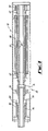
- FIG. 4 shows a different version of linear actuator in according with the invention, set up as a valve actuator.
- the linear actuator 70 shown in Fig. 4 has a motor section 72 at the right-hand side which is similar in essential respects to that of the actuator 30 described above in Fig. 1, and to which equivalent parts have been given the same reference numerals as in Fig. 1.
- the actuator 70 differs from the actuator 30 in that the driving member is an internally-threaded sleeve 74 mounted outboard of the motor section 72, secured to one end of one of the half-shafts 40.
- the sleeve 74 is radially and axially supported by a bearing 76.
- the actuator 70 further comprises a male-threaded driven member 78 with radially projecting dogs 80 which mesh with axially-extending splines 82 fixed within the actuator causing to allow the driven member 78 to move axially while being restrained from rotation.
- the left end of the driven member 78 is intended to actuate a valve (not shown), such as a ball or flapper valve, by axial movement of the driven member 78. Movement of the driven member 78 leftwards away from the motor section 72 would normally open such a valve, while rightward movement would cause or permit the valve to shut.
- a compression spring 84 biasses the driven member 78 in valve-closing inboard direction, and the angle of the threads linking the driving member 74 to the driven member 78 are made such as to allow both motorised rotation for valve opening, and spring-driven reverse rotation for fail-safe valve closure.
- the actuator 70 can be installed in-line in a pipeline or the like to actuate an adjacent in-line valve to control fluid flow along the pipeline.
- Fig. 5 shows parts of the actuator 70 of Fig. 4 to an enlarged scale, to illustrate a possible seal arrangement between the driving and driven members 74 and 78.
- the slidable but non-rotatable driven member 78 is sealed at its inboard (right-hand) end to the rotatable but non-slidable driving member 74 by means of a flexible sliding seal 86 mounted within a bearing 88 to minimise rotary friction, the bearing 88 being retained by a circlip 90.
- the driven member 78 is also sealed to the splines 82 by a further flexible sliding seal 92, which is retained by its own circlip 94.
- Fig. 6 is a schematic part-sectional isometric view of a linear-valve actuator generally similar to that shown in Fig. 4, but differing in detail. Equivalent parts have been accorded the same reference numerals as Fig. 4.
- Fig. 7 is a sectional elevation of an internally-threaded driving member 100 and an externally-threaded driven member 102 modified to act together as a secondary valve or back-up valve to the main valve (not shown) linearly actuated by the driven member 102 in an arrangement similar to that of Fig. 4 or Fig. 6.
- the members 100 and 102 have their axially facing portions shaped for mutual seating when fully screwed up to the illustrated position.
- the driving member 100 has an axial through port 104
- the driven member 102 has an axial through port 106.
- the ports 104 and 106 have different positions on the facing portions of the members 100 and 102 such that when these portions are fully seated, the ports 104 and 106 are out of alignment to shut off the flow of fluid allowed along the axis of the actuator when the members 100 and 102 are not fully seated.
- the ports 104 and 106 close off to provide a secondary closure and a functional back-up to the closure of the main valve.
- Fig. 8 shows a linear actuator 110 in conjunction with a combined dashpot and latch 112.
- the actuator 110 is powered by a rotary electric motor 114 whose rotor 116 is rotatably mounted on a pair of half-shafts 118 which are hollow to provide a through passage for the axially movable and non-rotatable linearly driven member 120.
- the linearly driven member 120 has a multi-start helix 122 which is acted on by a correspondingly threaded nut 124 clamped between the rotor half-shafts 118.
- the dashpot/latch mechanism 112 has a cylindrical casing 126 which acts as a cylinder to a dashpot piston 128 carried on the driven member 120.
- a compression spring 130 within the casing 126 urges the piston 128 and hence the driven member to the right (as viewed in Fig. 8).
- the driven member 120 is actuated to the left by anticlockwise rotation (as viewed on the left end of the actuator 110) against the force of the return spring 130, the bevelled rim of the piston 128 latches under a circumferential row of radially movable latches 132 which are solenoid-applied and spring released.
- the driven member 120 can be driven to an actuated position from which it will be automatically released upon power failure.
- Fig. 9 is a schematic diagram of a submarine well system 200 incorporating various of the above-described aspects of the invention.
- Item 201 is a valve actuator as shown in Fig. 8 and item 206 is a valve actuator of the type shown in Fig. 4 or alternatively that shown in Fig. 6.
- Items 203 and 205 are in-line pumps as described immediately above, while item 207 is an in-line electrical generator.
- Item 204 is an electrical distribution system).
Landscapes
- Engineering & Computer Science (AREA)
- General Engineering & Computer Science (AREA)
- Mechanical Engineering (AREA)
- Power Engineering (AREA)
- Physics & Mathematics (AREA)
- Fluid Mechanics (AREA)
- Electrically Driven Valve-Operating Means (AREA)
- Transmission Devices (AREA)
- Connection Of Motors, Electrical Generators, Mechanical Devices, And The Like (AREA)
Abstract
Description
- This invention relates to linear actuators and linear drive system.
- According to the present invention, a linear drive assembly comprises an electric motor having a non-rotatable stator and a hollow rotor, the rotor being rotatably mounted on a pair of half-shafts to form a hollow rotatable assembly rotatable about a rotation axis, the hollow rotatable assembly providing an axial through passage along the rotation axis, at least one female-threaded driving member secured to the rotatable assembly, and at least one corresponding male-threaded driven member non-rotatably mounted for linear actuation by the driving member along the rotation axis upon rotation of the rotatable assembly about the rotation axis.
- The driven member of the linear drive assembly may be mounted for non-rotatable and substantially axial movement through at least one end of the axial through passage provided by the hollow rotatable assembly, and the one driving member may be secured within the rotatable assembly between the half-shafts.
- Alternatively, the one driving member may be secured to one end of the rotatable assembly with the one driven member being non-rotatably mounted for substantially linear movement substantially coaxially with the rotation axis of the rotatable assembly.
- As a further alternative, the linear drive assembly may comprise two oppositely-handed female-threaded driving members secured to axially spaced-apart positions on the rotatable assembly, and two corresponding male-threaded driven members each non-rotatably mounted for linear actuation by a respective driven member in mutually opposite directions substantially along the rotation axis. The two driven members are preferably formed as matable valve members to control fluid flow in the through passage, the assembly being such that the valve members are linearly actuated in mutually opposite directions into and out of mutual contact whereby respectively to close and open the through passage to through flow of fluid.
- The driven member may be a valve actuating sleeve having an axial through bore coupled to the axial through passage conjointly to provide a fluid flow passage through the linear drive assembly. The axial through bore and the axial through passage preferably have mutually different radial offsets with respect to the rotation axis, with the driving and driven members having mutual seating portions such that in one relative linear position, the seating portions are mutually seated with the axial through bore and the axial through passage mutually offset to form a controllable closure of the fluid flow passage through the linear drive assembly.
- Embodiments of the invention will now be described by way of example with reference to the accompanying drawings wherein:-
- Fig. 1 is a longitudinal sectional elevation of a first embodiment;
- Fig. 2 is a longitudinal elevation of a pair of components of the first embodiment;
- Fig. 3 is a longitudinal sectional elevation of parts of the component pair of Fig. 2, in one operating position thereof;
- Fig. 4 is a longitudinal sectional elevation of a second embodiment;
- Fig. 5 is a longitudinal sectional elevation of part of the second embodiment of Fig. 4 to and enlarged scale, showing optional details thereof;
- Fig. 6 is an isometric part-sectional elevation of a third embodiment;
- Fig. 7. is a longitudinal sectional elevation of a modification of the third embodiment of Fig. 6;
- Fig. 8 is an isometric part-sectional elevation of a fourth embodiments; and
- Fig. 9 is a schematic diagram of a fluid system employing certain embodiments of the invention;
- Referring in Fig. 1, the first emobidiment is a
linear actuator 30 set up as a powered valve. Theactuator 30 comprises astator 32 non-rotatably secured within aframe 34 formed as a fluid-tight housing adapted for connection as part of a fluid pipeline (not shown) by means ofend flanges 36. Within theactuator 30 is a rotatable assembly comprising arotor 38 mounted on and keyed to a pair of half-shafts 40 rotatably supported on a pair of angularcontact ball bearings 42. At axially spaced-apart locations within the rotatable assembly and internally-threaded and oppositely-handed drive nuts shafts 40 for conjoint rotation with therotor 38. This rotatable assembly forms a through passage along the axis of theactuator 30, both for mechanical movement of actuated components and for fluid flow, as will be detailed below. - Centrally mounted within the
actuator 30 are a pair of drivenmembers frame 34 byrespective couplings 52 which allow relative sliding movement while preventing mutual rotation. The drivenmember 48 is externally threaded to match the internal thread of thedriving nut 44, and similarly, the drivenmember 50 is externally threaded to match the internal thread of thedriving nut 46. (These external threads are separately detailed in Fig. 2). - Since the two sets of corresponding male/female threads (on 44 with 48, and on 46 with 50) are oppositely handed, and since the driven
members actuator 30, energisation of thestator 32 to turn therotor 38 will turn thenuts members - The driven
members members valve seat 54 and avalve plug 56. By linearly driving thevalve seat 54 against thevalve plug 56 as detailed in Fig. 3, the through passage previously provided by theactuator 30 is controllably throttled shut, while reverse actuation will separate thevalve seat 54 from thevalve plug 56, as shown in Fig. 1, to re-open the axial passage through theactuator 30. Thus if theactuator 30 is coupled into an oil pipeline or a gas pipeline (by means of the end flanges 36), theactuator 30 can act as an in-line powered valve). - It is preferred that
springs 58 be provided within the rotatable assembly which tend to push the drivenmembers springs 58 are conveniently located inside the half-shafts 40 and around the peripheries of the drivenmembers Anti-friction bearings 60 allow free relative rotation of these components. A suitable choice of pitch angle for the threads of the drivingmembers 44 and 46 (necessarily matched by the corresponding threads on the drivenmembers 48 and 50) will result in the rotary-to-linear motion conversion mechanisms formed by these thread pairs being reversible. Thus in the absence of energisation of thestator 32, suitablystrong compression springs 58 will drive themembers rotor 38 undergoing force reverse rotation) to bring thevalve seat 54 and thevalve plug 56 together. Thereby the in-line valve provided by theactuator 30 will shut automatically in the event of electrical power failure. - Automatic valve closure of de-energisation of the
stator 32 can be inhibited by electrically operatedbrakes 62 which act between theframe 34 and the half-shafts 40. If thebrakes 62 are applied by energisation and release automatically on de-energisation, a power failure will release the half-shafts 40 to be reverse rotated by thesprings 58, thus allowing the valve to shut automatically on power failure while consuming only minimal power to hold the valve open. - Referring now to Fig. 4, this shows a different version of linear actuator in according with the invention, set up as a valve actuator. The
linear actuator 70 shown in Fig. 4 has amotor section 72 at the right-hand side which is similar in essential respects to that of theactuator 30 described above in Fig. 1, and to which equivalent parts have been given the same reference numerals as in Fig. 1. Theactuator 70 differs from theactuator 30 in that the driving member is an internally-threadedsleeve 74 mounted outboard of themotor section 72, secured to one end of one of the half-shafts 40. Thesleeve 74 is radially and axially supported by a bearing 76. - The
actuator 70 further comprises a male-threaded drivenmember 78 with radially projectingdogs 80 which mesh with axially-extendingsplines 82 fixed within the actuator causing to allow the drivenmember 78 to move axially while being restrained from rotation. The left end of the drivenmember 78 is intended to actuate a valve (not shown), such as a ball or flapper valve, by axial movement of the drivenmember 78. Movement of the drivenmember 78 leftwards away from themotor section 72 would normally open such a valve, while rightward movement would cause or permit the valve to shut. Acompression spring 84 biasses the drivenmember 78 in valve-closing inboard direction, and the angle of the threads linking thedriving member 74 to the drivenmember 78 are made such as to allow both motorised rotation for valve opening, and spring-driven reverse rotation for fail-safe valve closure. - The hollow half-
shafts 40 within themotor section 72, and a hollow bore through the drivenmember 78 together provide a through passage for fluid flow through theactuator 70 from end to end. Thus theactuator 70 can be installed in-line in a pipeline or the like to actuate an adjacent in-line valve to control fluid flow along the pipeline. - Fig. 5 shows parts of the
actuator 70 of Fig. 4 to an enlarged scale, to illustrate a possible seal arrangement between the driving and drivenmembers member 78 is sealed at its inboard (right-hand) end to the rotatable but non-slidabledriving member 74 by means of a flexible slidingseal 86 mounted within abearing 88 to minimise rotary friction, the bearing 88 being retained by a circlip 90. The drivenmember 78 is also sealed to thesplines 82 by a further flexible slidingseal 92, which is retained by itsown circlip 94. - Fig. 6 is a schematic part-sectional isometric view of a linear-valve actuator generally similar to that shown in Fig. 4, but differing in detail. Equivalent parts have been accorded the same reference numerals as Fig. 4.
- Fig. 7 is a sectional elevation of an internally-threaded
driving member 100 and an externally-threaded drivenmember 102 modified to act together as a secondary valve or back-up valve to the main valve (not shown) linearly actuated by the drivenmember 102 in an arrangement similar to that of Fig. 4 or Fig. 6. Themembers member 100 has an axial throughport 104, and the drivenmember 102 has an axial through port 106. Theports 104 and 106 have different positions on the facing portions of themembers ports 104 and 106 are out of alignment to shut off the flow of fluid allowed along the axis of the actuator when themembers member 102 is threaded rightwards to close the main valve, theports 104 and 106 close off to provide a secondary closure and a functional back-up to the closure of the main valve. - Fig. 8 shows a
linear actuator 110 in conjunction with a combined dashpot andlatch 112. As with the previous embodiments, theactuator 110 is powered by a rotaryelectric motor 114 whoserotor 116 is rotatably mounted on a pair of half-shafts 118 which are hollow to provide a through passage for the axially movable and non-rotatable linearly drivenmember 120. - The linearly driven
member 120 has a multi-start helix 122 which is acted on by a correspondingly threadednut 124 clamped between the rotor half-shafts 118. - The dashpot/
latch mechanism 112 has acylindrical casing 126 which acts as a cylinder to adashpot piston 128 carried on the drivenmember 120. Acompression spring 130 within thecasing 126 urges thepiston 128 and hence the driven member to the right (as viewed in Fig. 8). When the drivenmember 120 is actuated to the left by anticlockwise rotation (as viewed on the left end of the actuator 110) against the force of thereturn spring 130, the bevelled rim of thepiston 128 latches under a circumferential row of radiallymovable latches 132 which are solenoid-applied and spring released. Thus the drivenmember 120 can be driven to an actuated position from which it will be automatically released upon power failure. - Reverting momentarily to the "in-pipe"
linear actuator 30 of FIg. 1, if the drivingmembers member shafts 40, and their capability of holding a universal range of rotary articles or assemblies), the actuator 39 would be thereby converted to an in-line pump. Such a pump could be a positive displacement pump (which may be a Moineau pump), or an axial-flow hydrokinetic pump (either a single-stage pump, or a multi-stage pump). Further, such a pumping arrangement could be converted to an electrical generating system by driving the fluid side of the arrangement with fluid at a suitable flow rate and pressure, and extracting electrical power from the stator by suitable excitation of the electrical machine. - Fig. 9 is a schematic diagram of a
submarine well system 200 incorporating various of the above-described aspects of the invention.Item 201 is a valve actuator as shown in Fig. 8 anditem 206 is a valve actuator of the type shown in Fig. 4 or alternatively that shown in Fig. 6. (Items item 207 is an in-line electrical generator.Item 204 is an electrical distribution system). - Modifications and improvements may be made without departing from the scope of the invention.
Claims (6)
Applications Claiming Priority (2)
| Application Number | Priority Date | Filing Date | Title |
|---|---|---|---|
| GB8824041 | 1988-10-13 | ||
| GB888824041A GB8824041D0 (en) | 1988-10-13 | 1988-10-13 | Linear actuators & linear drive systems |
Publications (2)
| Publication Number | Publication Date |
|---|---|
| EP0364308A2 true EP0364308A2 (en) | 1990-04-18 |
| EP0364308A3 EP0364308A3 (en) | 1992-02-12 |
Family
ID=10645154
Family Applications (1)
| Application Number | Title | Priority Date | Filing Date |
|---|---|---|---|
| EP19890310589 Withdrawn EP0364308A3 (en) | 1988-10-13 | 1989-10-13 | Linear actuators and linear drive systems |
Country Status (6)
| Country | Link |
|---|---|
| US (1) | US5053660A (en) |
| EP (1) | EP0364308A3 (en) |
| JP (1) | JPH02223349A (en) |
| AU (1) | AU622491B2 (en) |
| GB (1) | GB8824041D0 (en) |
| NO (1) | NO894104L (en) |
Cited By (2)
| Publication number | Priority date | Publication date | Assignee | Title |
|---|---|---|---|---|
| WO2006127628A1 (en) * | 2005-05-20 | 2006-11-30 | Elliot Brooks | Eddy current inductive drive electromechanical linear actuator and switching arrangement |
| WO2020128443A1 (en) | 2018-12-21 | 2020-06-25 | Rotork Controls Limited | Actuator |
Families Citing this family (11)
| Publication number | Priority date | Publication date | Assignee | Title |
|---|---|---|---|---|
| US5637940A (en) * | 1994-04-05 | 1997-06-10 | Smc Kabushiki Kaisha | Electric Actuator |
| US6659200B1 (en) * | 1999-12-20 | 2003-12-09 | Halliburton Energy Services, Inc. | Actuator assembly and method for actuating downhole assembly |
| US6734582B2 (en) * | 2001-04-10 | 2004-05-11 | International Business Machines Corporation | Linear actuator using a rotating motor |
| DE10237644B4 (en) * | 2002-08-13 | 2006-01-19 | Zf Sachs Ag | Spring carrier with a height-adjustable spring plate |
| EP3501734B1 (en) | 2008-03-26 | 2024-06-12 | Quantum Servo Pumping Technologies Pty Ltd | Ultra high pressure pump with an alternating rotation to linear displacement drive mechanism |
| EP2623259A1 (en) * | 2012-02-06 | 2013-08-07 | Schneider GmbH & Co. KG | Linear drive with a balancing body |
| US10066715B2 (en) * | 2015-04-24 | 2018-09-04 | Moog Inc. | Fail-safe electromechanical actuator |
| US9906096B2 (en) * | 2015-04-28 | 2018-02-27 | Schaeffler Technologies AG & Co. KG | Eccentric leadscrew actuator |
| CN107453535A (en) * | 2017-08-21 | 2017-12-08 | 北京精密机电控制设备研究所 | A kind of Double-stroke electromechanical actuator |
| KR20220156622A (en) * | 2020-03-31 | 2022-11-25 | 그라코 미네소타 인크. | Electrically Operated Displacement Pump |
| WO2021202698A1 (en) * | 2020-03-31 | 2021-10-07 | Graco Minnesota Inc. | Electrically operated pump for a plural component spray system |
Citations (6)
| Publication number | Priority date | Publication date | Assignee | Title |
|---|---|---|---|---|
| GB887802A (en) * | 1959-08-14 | 1962-01-24 | Flight Refueling Ltd | Improvements in pipe couplings |
| US3421700A (en) * | 1966-08-03 | 1969-01-14 | Seamans Jr Robert C | Electromechanical actuator |
| DE2161605A1 (en) * | 1971-12-11 | 1973-06-14 | Linde Ag | MAGNETIC VALVE |
| GB2116460A (en) * | 1967-12-12 | 1983-09-28 | Kearney & Trecker Corp | Fixed screw and motorized ball nut mechanism for machine tool slide |
| US4480614A (en) * | 1980-10-06 | 1984-11-06 | Toyota Jidosha K.K. | Idling speed control device of an internal combustion engine |
| EP0257906A1 (en) * | 1986-08-14 | 1988-03-02 | Toyo Engineering Corporation | Valve |
Family Cites Families (4)
| Publication number | Priority date | Publication date | Assignee | Title |
|---|---|---|---|---|
| US2956188A (en) * | 1956-04-06 | 1960-10-11 | Fostoria Corp | Sealless motor for valve operation |
| US3461805A (en) * | 1968-02-26 | 1969-08-19 | Photo Instr Tooling Co | Reciprocating piston metering pump |
| US4145165A (en) * | 1977-03-04 | 1979-03-20 | California Institute Of Technology | Long stroke pump |
| US4277706A (en) * | 1979-04-16 | 1981-07-07 | Nu-Tech Industries, Inc. | Actuator for heart pump |
-
1988
- 1988-10-13 GB GB888824041A patent/GB8824041D0/en active Pending
-
1989
- 1989-10-13 AU AU42916/89A patent/AU622491B2/en not_active Ceased
- 1989-10-13 JP JP1265298A patent/JPH02223349A/en active Pending
- 1989-10-13 NO NO89894104A patent/NO894104L/en unknown
- 1989-10-13 EP EP19890310589 patent/EP0364308A3/en not_active Withdrawn
- 1989-10-13 US US07/420,923 patent/US5053660A/en not_active Expired - Fee Related
Patent Citations (6)
| Publication number | Priority date | Publication date | Assignee | Title |
|---|---|---|---|---|
| GB887802A (en) * | 1959-08-14 | 1962-01-24 | Flight Refueling Ltd | Improvements in pipe couplings |
| US3421700A (en) * | 1966-08-03 | 1969-01-14 | Seamans Jr Robert C | Electromechanical actuator |
| GB2116460A (en) * | 1967-12-12 | 1983-09-28 | Kearney & Trecker Corp | Fixed screw and motorized ball nut mechanism for machine tool slide |
| DE2161605A1 (en) * | 1971-12-11 | 1973-06-14 | Linde Ag | MAGNETIC VALVE |
| US4480614A (en) * | 1980-10-06 | 1984-11-06 | Toyota Jidosha K.K. | Idling speed control device of an internal combustion engine |
| EP0257906A1 (en) * | 1986-08-14 | 1988-03-02 | Toyo Engineering Corporation | Valve |
Cited By (8)
| Publication number | Priority date | Publication date | Assignee | Title |
|---|---|---|---|---|
| US7777600B2 (en) | 2004-05-20 | 2010-08-17 | Powerpath Technologies Llc | Eddy current inductive drive electromechanical liner actuator and switching arrangement |
| US8134438B2 (en) | 2004-05-20 | 2012-03-13 | Powerpath Technologies Llc | Electromechanical actuator |
| WO2006127628A1 (en) * | 2005-05-20 | 2006-11-30 | Elliot Brooks | Eddy current inductive drive electromechanical linear actuator and switching arrangement |
| US8134437B2 (en) | 2005-05-20 | 2012-03-13 | Powerpath Technologies Llc | Eddy current inductive drive electromechanical linear actuator and switching arrangement |
| WO2020128443A1 (en) | 2018-12-21 | 2020-06-25 | Rotork Controls Limited | Actuator |
| GB2580198A (en) * | 2018-12-21 | 2020-07-15 | Rotork Controls | Actuator |
| GB2580198B (en) * | 2018-12-21 | 2021-01-13 | Rotork Controls | Actuator |
| US11692638B2 (en) | 2018-12-21 | 2023-07-04 | Rotork Controls Limited | Actuator |
Also Published As
| Publication number | Publication date |
|---|---|
| US5053660A (en) | 1991-10-01 |
| NO894104D0 (en) | 1989-10-13 |
| GB8824041D0 (en) | 1988-11-23 |
| NO894104L (en) | 1990-04-17 |
| JPH02223349A (en) | 1990-09-05 |
| AU622491B2 (en) | 1992-04-09 |
| EP0364308A3 (en) | 1992-02-12 |
| AU4291689A (en) | 1990-04-26 |
Similar Documents
| Publication | Publication Date | Title |
|---|---|---|
| US5053660A (en) | Linear actuators and linear drive systems | |
| US5916325A (en) | Actuator assembly and torque limiting system for same | |
| EP1333207B1 (en) | Linear actuators | |
| EP2153098B1 (en) | Actuating device and method of operating an actuating device | |
| US20100270485A1 (en) | Valve Actuator | |
| EP2499411B1 (en) | Electric actuators having internal load apparatus | |
| AU2008214898B2 (en) | Flow control valve | |
| JP7030774B2 (en) | Final reduction ratio controller with electric actuator and electric actuator | |
| US10563787B2 (en) | Electric actuator system and method | |
| EP3631243B1 (en) | Fault-tolerant electromechanical linear actuator | |
| EP2499410A1 (en) | Coupling apparatus for use with electric actuators | |
| US6923212B2 (en) | Fail safe apparatus for a direct-drive servovalve | |
| WO2003064905A1 (en) | Electric valve actuator with eddy current clutch | |
| WO2007045858A1 (en) | Improvements in linear actuators | |
| US20100308240A1 (en) | Electric fail safe valve actuator | |
| US20060060708A1 (en) | Locking device for vehicles, in particular for aeroplanes | |
| US4530271A (en) | Electric actuator system with hydraulic coupling as protection against mechanical jamming | |
| US8979506B2 (en) | Reverse rotation prevention device | |
| US6957801B2 (en) | Valve having an integrated actuator assembly | |
| GB2276209A (en) | Electrohydraulic valve actuator | |
| US4884495A (en) | Fluid motor actuator with compression spring fail-safe mechanism | |
| RU2076980C1 (en) | Gas-tight valve | |
| US20150240963A1 (en) | Electrical actuator | |
| CA1056691A (en) | Hydraulic actuated control valve | |
| RU2213890C2 (en) | Ball cock pneumatic drive with jet motor and its manual stand-by operator |
Legal Events
| Date | Code | Title | Description |
|---|---|---|---|
| PUAI | Public reference made under article 153(3) epc to a published international application that has entered the european phase |
Free format text: ORIGINAL CODE: 0009012 |
|
| AK | Designated contracting states |
Kind code of ref document: A2 Designated state(s): AT BE DE ES FR GB GR IT NL SE |
|
| PUAL | Search report despatched |
Free format text: ORIGINAL CODE: 0009013 |
|
| AK | Designated contracting states |
Kind code of ref document: A3 Designated state(s): AT BE DE ES FR GB GR IT NL SE |
|
| 17P | Request for examination filed |
Effective date: 19920226 |
|
| 17Q | First examination report despatched |
Effective date: 19930331 |
|
| STAA | Information on the status of an ep patent application or granted ep patent |
Free format text: STATUS: THE APPLICATION IS DEEMED TO BE WITHDRAWN |
|
| 18D | Application deemed to be withdrawn |
Effective date: 19931012 |